Table of Contents
Advertisement
Quick Links
Advertisement
Table of Contents

Related Manuals for Multitech REVEAL RBS304-1


Summary of Contents for Multitech REVEAL RBS304-1
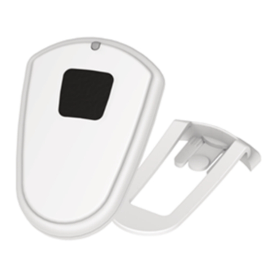
- Page 1 Reveal Wireless Single Push Button User Guide...
- Page 2 Trademarks and Registered Trademarks MultiTech, the MultiTech logo, DeviceHQ, xDot, and Conduit are registered trademarks and Reveal and mDot are trademarks of Multi-Tech Systems, Inc. All other products and technologies are the trademarks or registered trademarks of their respective holders.
-
Page 3: Table Of Contents
CONTENTS Contents Chapter 1 – Product Overview ..........................4 Sensor Overview ................................4 Part Number.................................. 4 Documentation ................................4 Chapter 2 – Preparing Sensor........................... 5 Preparing an RBS301 Sensor............................5 Preparing an RBS306 Sensor............................5 Quick Start..................................5 Chapter 3 – Hardware Specifications and Information ..................... 7 Absolute Maximum Ratings ............................ -
Page 4: Chapter 1 - Product Overview
RBS304-1-EU Indoor LoRaWAN Europe RBS304-1-AU Indoor LoRaWAN Australia, South America Documentation The following documentation is available at https://www.multitech.com/brands/reveal-wireless-push-buttons. Document Description Part Number User Guide This document provides overview, safety and regulatory RB00010 information, design considerations, schematics, and general hardware information. -
Page 5: Chapter 2 - Preparing Sensor
Console, use the following steps. To use a third-party network, refer to the Connecting Radio Bridge LoRaWAN Sensors on Gateways and Networks (RB00001) , which is available through the sensor page at https://www.multitech.com/products/sensors Create a Radio Bridge console account at: https://console.radiobridge.com/... - Page 6 PREPARING SENSOR Note: For easy Device ID and Key entry, scan the QR code on the device label. Then copy and paste data into the console. With the QR code, the first line is the Device ID and the rest is the key. Select the model from the Device Type drop down.
-
Page 7: Chapter 3 - Hardware Specifications And Information
Refer to the Sensor Battery Estimator.xlsx spreadsheet on the on the sensor's product page for specific battery life estimates: https://www.multitech.com/products/sensors Battery life depends on the number of transmissions per day. Power required for a message transmission is greater than the “sleep current” for high power radio technologies (e.g, LoRaWAN). -
Page 8: Mechanical Drawing
HARDWARE SPECIFICATIONS AND INFORMATION Mechanical Drawing The mechanical drawings provided in this section are for the main body of the sensor. All dimensions use inches unless specified. Reveal Wireless Single Push Button User Guide... -
Page 9: Chapter 4 - Common Messages
Sensor Specific Messages chapter. Message Protocol This section defines the protocol and message definitions for the device. Note: MultiTech provides a web-based console at console.radiobridge.com for configuring and monitoring devices. We recommend using this console rather than the protocols defined in this section. -
Page 10: Reset Message 0X00
COMMON MESSAGES Message Payload Description 0xfe Reserved. 0xff 1-byte status Downlink message ACK. Refer to Downlink ACK for more detail. Reset Message 0x00 Every time a sensor resets it sends a reset message to the cloud. The reset message payload is defined in the following table. Bytes Description Sensor type code, a product identifier sent as part of the reset message. -
Page 11: Supervisory Message 0X01
COMMON MESSAGES Supervisory Message 0x01 Wireless sensors periodically send a supervisory message so the backend system can verify the device is still alive and report error conditions. The supervisory message payload include current sensor status. The following table shows the supervisory message payload: Bytes Description Supervisory error codes as follows:... -
Page 12: Downlink Messages
COMMON MESSAGES Downlink Messages Downlink messages are from the cloud to the sensor and are used to configure the sensor. The sensor initiates downlink messages, since the sensor is typically sleeping with the radio turned off. For LoRaWAN devices, a downlink can be received after any uplink within the receive window. The following messages can be sent back to the sensor upon a downlink request. - Page 13 COMMON MESSAGES Radio Config The following table shows the radio config byte definition. Note: Available in firmware version 1.4 or newer. Bits Description Not used (reserved) Enable duty cycle requirement. LoRaWAN EU868 only. To enforce the EU868 band duty cycle requirements, enable before production deployment.
-
Page 14: Advanced Configuration
COMMON MESSAGES Bit 7:6 Bits 5:0 Sampling period defined in increments of 250ms (0.25-15 seconds). Sampling period defined in increments of seconds (1-63 seconds). Sampling period defined in increments of minutes (1-63 minutes). Sampling period defined in increments of hours (1-63 hours). Advanced Configuration Use this command for advanced configuration parameters that apply to all sensor types. -
Page 15: Downlink Ack
COMMON MESSAGES Downlink ACK The cloud app uses this downlink ACK message to verify the that sensor received the downlink message received and it was considered valid. The sensor replies to the downlink data with a 0xFF message (downlink ACK) with the payload shown in the following table. -
Page 16: Chapter 5 - Sensor-Specific Messages
SENSOR-SPECIFIC MESSAGES Chapter 5 – Sensor-Specific Messages Uplink Messages The following table shows sensor specific uplink messages (sensor to web application). Uplink messages common to all sensors are in the previous chapter. Button ID Event Payload Description 0x03 0x00 Button pressed 0x03 0x01 Button released... - Page 17 SENSOR-SPECIFIC MESSAGES Bits Description Blinks LED after message ACK is received (confirmed messages only). 0 means LED blinks after a device receives an ACK message ACK. 1 means LED doesn’t blink after a receiving an ACK message ACK. Does not apply to unconfirmed messages. Blinks LED after a send.
-
Page 18: Chapter 6 - Regulatory Information
(1) This device may not cause harmful interference, and (2) this device must accept any interference received, including interference that may cause undesired operation. Per FCC 15.21, Changes or modifications not expressly approved by MultiTech could void authority to operate the devices.