Advertisement
Quick Links
Advertisement

Related Manuals for KTM 890 ADVENTURE 2022


Summary of Contents for KTM 890 ADVENTURE 2022
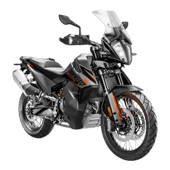
- Page 1 SETUP INSTRUCTIONS 2022 890 ADVENTURE 890 ADVENTURE L Art. no. 3214568en...
- Page 3 KTM accepts no liability for delivery options, deviations from fig- ures and descriptions, misprints, and other errors. The models portrayed partly contain special equipment that does not belong to the regular scope of supply.
-
Page 4: Means Of Representation
1 MEANS OF REPRESENTATION Symbols used The meaning of specific symbols is described below. Indicates an expected reaction (e.g. of a work step or a function). Indicates an unexpected reaction (e.g. of a work step or a function). Indicates a page reference (more information is provided on the specified page). Indicates information with more details or tips. - Page 5 To operate the vehicle, the vehicle electronics must be enabled. This process is conducted during initial setup in KTM Dealer.net. Enabling ensures that the initial setup in KTM Dealer.net is docu- mented. Enabling can be performed either temporarily, e.g. for a test ride, or permanently for vehicle handover.
- Page 6 2 SETUP – Roll down the film at the sides. Guideline To avoid damaging the vehicle while setting it up, do not remove the protective film on each component until installing the component, and leave it on the vehicle until work has been completed.
- Page 7 SETUP 2 Handlebar scale markings are located centrally between the handlebar clamps. Info Keep the installed gap widths equal when tightening. – Check the handlebar position. » If the handlebar position is not adjusted as required by the customer: – Adjust the handlebar position.
- Page 8 2 SETUP – Position the brake assembly on the handlebar. – Position brake assembly clamp on the handlebar. The holding lug of the clamp engages in the combination switch. – Mount and tighten screws Guideline Screw, brake assem- 5 Nm (3.7 lbf ft) F02131-10 –...
- Page 9 SETUP 2 – Mount and tighten the rear mirror on both sides. F02144-01 – Mount rubber bushings on windshield – Mount windshield on windshield bracket The windshield engages on the left and right in the recesses of the windshield bracket. –...
- Page 10 2 SETUP (EU) – Mount reflector with rubber bushings and tension washers on the license plate holder – Position the license plate bracket on the license plate sup- port. – Mount and tighten screws Guideline Screw, license 5 Nm (3.7 lbf ft) Loctite ®...
- Page 11 SETUP 2 – Position the left fuel tank cover. – Mount and tighten screws with the collar bushings and the absorbing elements. Guideline Screw, fuel tank M6x22 8 Nm (5.9 lbf ft) cover – Position the right fuel tank cover. –...
- Page 12 2 SETUP – Mount screws , but do not tighten yet. Guideline Screw, engine guard M6x8 8 Nm (5.9 lbf ft) F02140-10 – Mount screws , but do not tighten yet. Guideline Screw, fuel tank M6x12 8 Nm (5.9 lbf ft) cover The engine guard is directed evenly toward the front.
- Page 13 Install the left side cover. ( p. 15) – Remove the labels from the brake line and the frame. – Unpack and mount the KTM PowerParts included in the deliv- ery (optional). Info Read the accompanying KTM PowerParts fitting instruc- tions.
- Page 14 3 WORK Adjusting the handlebar position Warning Danger of accidents A repaired handlebar poses a safety risk. If the handlebar is bent or straightened, the material becomes fatigued. The handlebar may break as a result. – Change the handlebar if the handlebar is damaged or bent. –...
- Page 15 WORK 3 Mounting the passenger seat – Hook holding lugs of the passenger seat into the bushings on the subframe, lower the front, and simultaneously push back- ward. – Insert locking pin into the lock housing and push down the front of the passenger seat until the locking pin engages with an audible click.
- Page 16 3 WORK Removing the left side cover Preparatory work – Remove the passenger seat. ( p. 12) – Remove the front rider's seat. ( p. 13) Main work – Remove left side cover from the rubber bushings in the areas –...
- Page 17 WORK 3 Closing the storage compartment on the left Main work – Close the storage compartment. – Raise elastic fastener and hang up in area F01899-10 Finishing work – Install the left side cover. ( p. 15) – Mount the front rider's seat. ( p.
- Page 18 3 WORK 3.10 Removing the right side cover Preparatory work – Remove the passenger seat. ( p. 12) – Remove the front rider's seat. ( p. 13) Main work – Remove the side cover from the rubber bushings in areas –...
- Page 19 WORK 3 3.12 Closing the storage compartment on the right Main work – Close the storage compartment. – Raise elastic fastener and hang up in area F01901-10 Finishing work – Install the right side cover. ( p. 17) – Mount the front rider's seat. ( p.
- Page 20 3 WORK 3.14 Removing the battery cover Preparatory work – Remove the passenger seat. ( p. 12) – Remove the front rider's seat. ( p. 13) Main work – Remove screws with the bushings. – Remove the battery cover from above. F02044-10 3.15 Installing the battery cover...
- Page 21 WORK 3 3.16 Charging the 12-V battery Warning Risk of injury Battery acid and battery gases cause serious chemical burns. – Keep 12 V batteries out of the reach of children. – Wear suitable protective clothing and safety glasses. – Avoid contact with battery acid and battery gases. –...
- Page 22 3 WORK Info Follow the instructions of the charger and the manual. – Disconnect the battery charger after charging the 12-V battery. Guideline The charging current, charging voltage, and charging time must not be exceeded. Recharge the 12-V battery 3 months regularly when the motorcy- cle is not being used Finishing work...
- Page 23 WORK 3 3.18 Connecting the negative cable of the 12-V battery Warning Risk of injury Battery acid and battery gases cause serious chemical burns. – Keep 12 V batteries out of the reach of children. – Wear suitable protective clothing and safety glasses. –...
- Page 24 3 WORK – The rider now mounts the motorcycle with luggage and passen- ger if applicable. – Check the headlight setting. The light-dark boundary must be exactly on the lower mark- ing when the motorcycle is ready to be operated with the rider mounted along with any luggage and a passenger if applicable.
- Page 25 WORK 3 – Position left mask spoiler. – Mount and tighten screws Guideline Remaining screws, 5 Nm (3.7 lbf ft) chassis F01992-10 3.21 Refueling Danger Fire hazard Fuel is highly flammable. The fuel in the fuel tank expands when warm and can escape if overfilled. –...
- Page 26 3 WORK – Switch off the engine. – Open the fuel tank filler cap. ( p. 24) – Fill the fuel tank with fuel up to the lower edge of the filler neck. Total fuel tank 20 l Super unleaded capacity, approx.
- Page 27 WORK 3 – Lift cover of the fuel tank filler cap and insert the ignition key into the lock. Note Danger of damage The ignition key may break if overloaded. Damaged ignition keys must be replaced. – Push down on the fuel tank filler cap to take pressure off the ignition key.
-
Page 28: Technical Data
4 TECHNICAL DATA Chassis tightening torques Brake fluid reservoir cover, front 1 Nm (0.7 lbf ft) Brake fluid reservoir cover, rear 1.5 Nm (1.11 lbf ft) Compensating tank cover 1.1 Nm (0.81 lbf ft) Nut, valve ISO 10V2 12 Nm (8.9 lbf ft) Loctite ®... - Page 29 TECHNICAL DATA 4 Screw, lower rear panel 3 Nm (2.2 lbf ft) Screw, mask support 3.5 Nm (2.58 lbf ft) Screw, mask support cover 3.5 Nm (2.58 lbf ft) Screw, side stand sensor 2 Nm (1.5 lbf ft) Loctite ® 243™...
- Page 30 4 TECHNICAL DATA Screw, fuel pump 6 Nm (4.4 lbf ft) Screw, fuel tank clamp 3 Nm (2.2 lbf ft) Screw, fuel tank cover M6x12 8 Nm (5.9 lbf ft) Screw, fuel tank cover M6x22 8 Nm (5.9 lbf ft) Screw, fuel tank spoiler attach- 3 Nm (2.2 lbf ft) ment...
- Page 31 TECHNICAL DATA 4 Screw, foot brake lever return 12 Nm (8.9 lbf ft) Loctite ® 2701™ spring bolt Screw, fork stub 15 Nm (11.1 lbf ft) Screw, front brake caliper 25 Nm (18.4 lbf ft) Screw, grab handle 25 Nm (18.4 lbf ft) Loctite ®...
- Page 32 4 TECHNICAL DATA Screw, bottom shock absorber 80 Nm (59 lbf ft) Loctite ® 2701™ Screw, swingarm pivot 100 Nm (73.8 lbf ft) Screw, top shock absorber 80 Nm (59 lbf ft) Loctite ® 2701™ Lambda sensor M18x1.5 50 Nm (36.9 lbf ft) Adjusting screw, swingarm M20LHx1.5 10 Nm (7.4 lbf ft)
- Page 33 SUBSTANCES 5 Super unleaded (ROZ 95) Standard/classification – DIN EN 228 (ROZ 95) Guideline – Only use super unleaded fuel that matches or is equivalent to the specified standard. – Fuel with an ethanol content of up to 10% (E10 fuel) is safe to use. Info Do not use fuel containing methanol (e.g., M15, M85, M100) or more than 10% ethanol (e.g., E15, E25, E85, E100).
- Page 34 *3214568en* 3214568en 09/2021 KTM Sportmotorcycle GmbH 5230 Mattighofen/Austria Photo: Mitterbauer/KISKA/KTM KTM.COM...