Table of Contents
Advertisement
Quick Links
We advise you to read this manual carefully, as it contains all the instructions for maintaining
the appliance's aesthetic and functional qualities.
For further information on the product: www.smeg.com
Contents
4
4
9
9
9
9
10
10
11
11
12
12
13
16
16
17
17
18
20
22
22
24
30
30
30
31
31
32
32
34
34
34
37
38
41
43
3
Advertisement
Table of Contents

Related Manuals for Smeg A3AU-81


Summary of Contents for Smeg A3AU-81
-
Page 1: Table Of Contents
5.3 Adaptation to different types of gas 5.4 Positioning 5.5 Electrical connection 5.6 Instructions for the installer We advise you to read this manual carefully, as it contains all the instructions for maintaining the appliance’s aesthetic and functional qualities. For further information on the product: www.smeg.com... -
Page 2: Instructions
Instructions 1 Instructions • Keep children under the age of 8 away from the appliance when it 1.1 General safety instructions is in use. • Cleaning and maintenance must Risk of personal injury not be carried out by • During use the appliance and its unsupervised children. - Page 3 Instructions • Do not place metal objects, such • DO NOT USE AEROSOLS IN as dishes or cutlery, on the hob THE VICINITY OF THIS surface during use as they may APPLIANCE WHILST IT IS IN overheat. USE. • Do not insert pointed metal objects •...
- Page 4 Instructions damaged, contact technical • Do not spray any spray products support immediately and they will near the oven. replace it. • Do not use plastic cookware or containers when cooking food. Risk of damaging the appliance • Do not put sealed tins or •...
- Page 5 Instructions • Do not use a steam cleaner to • The appliance must not be clean the appliance. installed on a pedestal. • Do not use harsh abrasive • Position the appliance into the cleaners or sharp metal scrapers cabinet cut-out with the help of a to clean the oven glass door since second person.
- Page 6 Instructions • If this cooking range is to be • If the range is not fitted with a connected to a new or upgraded flexible cord, the instruction electrical installation, then it must manual must clearly state the type be connected by a supply cord and size of cord to be used.
-
Page 7: Identification Plate
Instructions For this appliance • tampering with any part of the appliance; • WARNING: Ensure that the • the use of non-original spare appliance is switched off before parts. replacing the lamp to avoid the possibility of electric shock. 1.4 Appliance purpose •... -
Page 8: To Save Energy
Instructions 1.6 To save energy 1.7 How to read the user manual • Only preheat the appliance if the This user manual uses the following reading conventions: recipe requires you to do so. • Unless otherwise indicated on the Instructions package, defrost frozen foods General information on this user before placing them in the oven. -
Page 9: Description
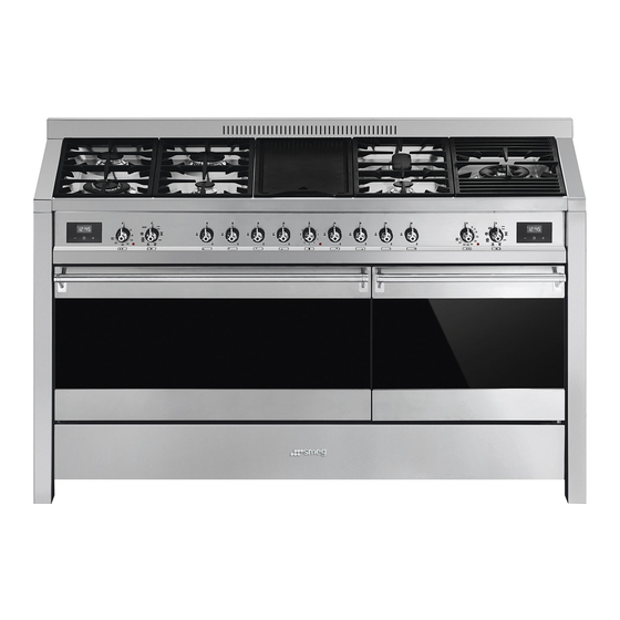
Description 2 Description 2.1 General Description 1 Cooking hob 6 Fan 2 Control panel 7 Inside lights 3 Seals 8 Storage compartment 4 Main oven door Rack/tray support frame shelf 5 Auxiliary oven door... -
Page 10: Cooking Hob
Description 2.2 Cooking hob AUX = Auxiliary burner R = Rapid burner SR = Semi-rapid burner UR2 = Ultra-rapid burner FB = Fish kettle burner BBQ = Barbecue plate 2.3 Control panel 1 Programmer clock 3 Main oven indicator light Useful for displaying the current time, setting The indicator light comes on to indicate that programmed cooking operations and... -
Page 11: Other Parts
Description 2.4 Other parts 5 Hob burner knobs Used for lighting and adjusting the hob Shelves burners. Press and turn the knobs anti- The appliance features shelves to position clockwise to in order to light the relative trays and racks at different heights. The burners. - Page 12 Description Available accessories The pan support must be placed on the hob grid as shown in the figure above. In any case, pans with a diameter greater than 26 Not all accessories are available cm must be used solely on the Ultra-rapid on some models.
- Page 13 Description Tray rack Rack Used for supporting containers with food during cooking. The oven accessories intended to come into contact with food are made of materials that comply with the provisions of current legislation. Original supplied and optional To be placed over the top of the oven tray; accessories can be requested to for cooking foods which may drip.
-
Page 14: Use
3 Use Improper use Danger of burns 3.1 Instructions High temperature inside the oven • Make sure that the flame-spreader during use crowns are correctly positioned in their seats with their respective burner caps. Danger of burns • Oils and fats could catch fire if •... -
Page 15: First Use
3.2 First use Improper use 1. Remove any protective film from the Risk of damage to surfaces outside or inside of the appliance, including accessories. • Do not cover the bottom of the oven 2. Remove any labels (apart from the cavity with aluminium or tin foil sheets. -
Page 16: Using The Hob
and towards the oven back. 3.4 Using the hob All the appliance’s control and monitoring devices are located together on the front panel. The burner controlled by each knob is shown next to the knob. The appliance is equipped with an electronic ignition device. Simply press the knob and turn it anti- clockwise to the maximum flame symbol, until the burner ignites. - Page 17 Correct positioning of the flame- Barbecue plate spreader crowns and burner caps High temperature Before lighting the hob burners, make sure Danger of burns that the flame-spreader crowns are correctly positioned in their seats with their • After prolonged use, the hot plate respective burner caps.
-
Page 18: Using The Ovens
3. In the tray under the heating element you 3.5 Using the ovens can put: Switching on the main oven • Water to catch the fat and any grease To switch on the oven: dripping from the cooking 1. Select the cooking function using the •... - Page 19 Small grill Fan with round heating element. Using only the heat released from The combination of the fan and the the central element, this function round heating element allows you to grill small portions of (incorporated in the rear of the meat and fish for making kebabs, oven) allows you to cook different toasted sandwiches and any types...
-
Page 20: Using The Storage Compartment
Auxiliary oven functions Wide grill The heat coming from the grill Static element gives perfect grilling results As the heat comes from above and above all for thin and medium below at the same time, this system thickness meat and, in combination is particularly suitable for certain with the rotisserie (where fitted), types of food. - Page 21 • Use a meat thermometer when roasting • If the dessert collapses when it comes meat, or simply press on the roast with a out of the oven, on the next occasion spoon. If it is hard, it is ready; If not, it reduce the set temperature by about needs another few minutes cooking.
-
Page 22: Programmer Clock
3.8 Programmer clock Setting the time If the time is not set, the oven will not switch on. On the first use, or after a power failure, the digits will be flashing on the appliance’s display. 1. Hold down the clock key for two seconds. - Page 23 Timed cooking 7. Press the clock key to reset the programmer clock. Timed cooking is the function which allows a cooking operation It is not possible to set a cooking to be started and then ended after time of more than 10 hours. a specific length of time set by the user.
- Page 24 10. Return the function and temperature 4. Use the key to set the knobs to 0. required minutes. (for example 1 hour) 11. To turn off the buzzer just press any key 5. Press the menu key . The text of the programmer clock.
- Page 25 Modifying the set data Minute minder timer 1. Press the clock key The minute minder timer does not stop the cooking operation but 2. Use the value increase and value rather informs the user when the set time has run out. decrease keys to set the number of minutes required.
- Page 26 Main oven cooking information table Runner Temperature Weight Food Function position from Time (minutes) (Kg) (°C) the bottom Lasagne 3 - 4 Static 220 - 230 45 - 50 Pasta bake 3 - 4 Static 220 - 230 45 - 50 Roasted veal Fan with round heating element.
- Page 27 Auxiliary oven cooking information table Runner Temperature Weight Food Function position from Time (minutes) (Kg) (°C) the bottom Spit-roast chicken Rotisserie 220 - 250 70 - 80 Rotisserie pork neck Rotisserie 200 - 220 Roast rabbit Static 190 - 200 85 - 90 Roast chicken Static...
-
Page 28: Cleaning And Maintenance
Cleaning and maintenance 4 Cleaning and maintenance Use normal, non-abrasive products and a wooden or plastic tool, if necessary. Rinse 4.1 Instructions thoroughly and dry with a soft cloth or a microfibre cloth. Improper use Do not allow residues of sugary foods (such Risk of damage to surfaces as jam) to set inside the oven. -
Page 29: Removing The Doors
Cleaning and maintenance Igniters and thermocouples 2. Grasp the door on both sides with both hands, lift it forming an angle of around For correct operation the igniters and 30° and remove it. thermocouples must always be perfectly clean. Check them frequently and clean them with a damp cloth if necessary. -
Page 30: Cleaning The Inside Of The Ovens
Cleaning and maintenance 4.5 Cleaning the inside of the ovens Removing racks/trays support frames To keep the ovens in perfect condition, Removing the guide frames enables the clean them regularly after allowing them to sides to be cleaned more easily. cool. - Page 31 Cleaning and maintenance 1. Remove the bulb protector (A) by Installing and removing the seal turning it anticlockwise. To remove the seal: 2. Replace the bulb with one of the same To permit thorough cleaning of the auxiliary type (B). oven, the door seal can be removed.
-
Page 32: Installation
Installation 5 Installation 5.1 Minimum clearance to combustible surfaces Freestanding cooker 5.2 Gas connection Gas leak Danger of explosion • After carrying out any operation, check that the tightening torque of gas connections is between 10 Nm and 15 Nm. •... - Page 33 1.0 kPa when approximately 50% of the burners are on high flame, the appliance test point is located on the regulator. Patent 2015101170. For enquires contact Gas Approval Consulting Pty Ltd Smeg licence 045 for GAS40079...
- Page 34 Installation Room ventilation When the job is complete, the installer must issue a certificate of conformity. The appliance should be installed in rooms that have a permanent air supply in accordance with the standards in force. The room where the appliance is installed must have enough air flow for the regular combustion of gas and the necessary air change in the room itself.
-
Page 35: Adaptation To Different Types Of Gas
Installation 5.3 Adaptation to different types of Adjusting the minimum setting for natural or town gas In case of operation with other types of gas, Light the burner and turn it to the minimum the burner nozzles must be changed and position. -
Page 36: Positioning
Installation Adjusting the minimum setting for LPG Tighten the screw located at the side of the cock rod clockwise all the way. Following adjustment to a gas other than the one originally set in the factory, replace the gas setting label on the appliance with the one corresponding to the new gas. - Page 37 Installation Dimensions 1. Use the adjustable feet to level the appliance until it is level and stable on Position of gas and electrical connections the ground. (all measurements expressed in mm). 2. Fasten a hook bolt (not supplied) into the wall at a height (H) of 800 mm from the floor.
- Page 38 Installation 5. Connect the snap hook to the Assembling the upstand appropriate hole on the back of the The upstand provided is an appliance. integral part of the product; it must be fastened to the appliance prior to installation. The upstand must always be positioned and secured correctly on the appliance.
-
Page 39: Electrical Connection
Installation 5.5 Electrical connection • an appropriately rated installation male connector that is compatible with the Power voltage installation female connector fitted to tge Danger of electrocution final sub-circuit in the fixed wiring that supplies this cooking range. • Have the electrical connection The appliance can work in the following performed by authorised technicians. -
Page 40: Instructions For The Installer
Installation Fixed connection 5.6 Instructions for the installer • The appliance must be installed Install an all-pole disconnection device in according to the installation diagrams. the power line that ensures full disconnection from the mains supply and • Do not try to unscrew or force the which has a contact opening distance that threaded elbow of the fitting.