Table of Contents
Advertisement
Quick Links
Advertisement
Table of Contents

Related Manuals for Asus Z97I-PLUS


Summary of Contents for Asus Z97I-PLUS
- Page 1 Z97I-PLUS...
- Page 2 INCIDENTAL, OR CONSEQUENTIAL DAMAGES (INCLUDING DAMAGES FOR LOSS OF PROFITS, LOSS OF BUSINESS, LOSS OF USE OR DATA, INTERRUPTION OF BUSINESS AND THE LIKE), EVEN IF ASUS HAS BEEN ADVISED OF THE POSSIBILITY OF SUCH DAMAGES ARISING FROM ANY DEFECT OR ERROR IN THIS GUIDE OR PRODUCT.
-
Page 3: Table Of Contents
Contents Safety information ...................... vi About this guide ......................vii Z97I-PLUS specifications summary ................. ix Package contents ..................... xiii Installation tools and components ................. xiv Chapter 1: Product Introduction Special features..................1-1 1.1.1 Product highlights................ 1-1 1.1.2 5X Protection................1-2 1.1.3... - Page 4 ..........3-40 ..............3-41 ............. 3-42 Monitor menu ................... 3-43 Boot menu ....................3-46 Tool menu ....................3-52 3.9.1 ASUS EZ Flash 2 Utility ............3-52 ............3-52 3.9.3 ASUS SPD Information ............. 3-53 3.10 Exit menu ....................3-54 3.11 Updating BIOS ..................
- Page 5 Creating a RAID driver disk without entering the OS ....5-7 ® 5.2.2 Creating a RAID driver disk in Windows ........5-8 ® 5.2.3 Installing the RAID driver during Windows OS installation ..5-8 Appendices Notices ........................A-1 ASUS contact information ..................A-3...
-
Page 6: Safety Information
Safety information Electrical safety before relocating the system. When adding or removing devices to or from the system, ensure that the power cables for the devices are unplugged before the signal cables are connected. If possible, disconnect all power cables from the existing system before you add a device. Before connecting or removing signal cables from the motherboard, ensure that all power cables are unplugged. -
Page 7: About This Guide
Refer to the following sources for additional information and for product and software updates. ASUS websites The ASUS website provides updated information on ASUS hardware and software products. Refer to the ASUS contact information. Optional documentation that may have been added by your dealer. These documents are not part of the... - Page 8 Conventions used in this guide To ensure that you perform certain tasks properly, take note of the following symbols used throughout this guide. DANGER/WARNING: Information to prevent injury to yourself when trying to complete a task. CAUTION: Information to prevent damage to the components when trying to complete a task IMPORTANT: Instructions that you MUST follow to complete a task.
-
Page 9: Z97I-Plus Specifications Summary
Z97I-PLUS specifications summary LGA1150 socket for the 4th Generation, New 4th Generation and 5th Generation Intel ® Core™ i7 / Core™ i5 / Core™ i3, Pentium ® , and Celeron ® processors Supports 22nm CPU ® Supports Intel Turbo Boost Technology 2.0* * The Intel ®... - Page 10 - 6 x USB 2.0/1.1 ports (2 ports at mid-board, 4 ports at rear panel) ASUS unique features High Performance ASUS 5X PROTECTION - ASUS motherboards safeguard your PC with 5X Protection: DIGI+ Power Control, DRAM Fuse, ESD Guards, High-Quality Solid Capacitors, and Stainless Steel Back I/O to ensure the best quality, reliability, anddurability...
- Page 11 ASUS exclusive Quiet Thermal Design overclocking features - ASUS Fan Xpert 3 - ASUS Fanless Design: Heat-sink solution Precision Tweaker 2 - vCore: Adjustable CPU Core voltage at 0.001V increment - iGPU: Adjustable CPU Graphics voltage at 0.001V increment - vCCIO: Adjustable Analog and Digital I/O voltage at 0.001V increment - vCCIN: Adjustable CPU Input voltage at 0.01V increment...
- Page 12 1 x TPM header BIOS features 64 Mb Flash ROM, UEFI AMI BIOS, PnP, DMI 2.7, WfM 2.0, SM BIOS 2.7, ACPI 5.0, Multi-language BIOS, ASUS EZ Flash 2, ASUS Shortcut functions, and ASUS DRAM SPD (Serial Presence Detect) memory information Manageability WfM 2.0, DMI 2.7, WOL by PME, PXE...
-
Page 13: Package Contents
Package contents Check your motherboard package for the following items ASUS Z97I-PLUS motherboard User guide Support DVD 1 x 2T2R dual-band Wi-Fi moving 4 x Serial ATA 6.0 Gb/s cables 1 x ASUS Q-Shield antenna (Wi-Fi 802.11a/b/g/n/ac compliant) 1 x ASUS Q-Connector 1 x 2-in-1 Wi-Fi antenna connector with different models. -
Page 14: Installation Tools And Components
Installation tools and components 1 bag of screws Philips (cross) screwdriver PC chassis Power supply unit ® ® Intel LGA1150 CPU Intel LGA1150 compatible CPU Fan DIMM SATA hard disk drive SATA optical disc drive (optional) Graphics card (optional) The tools and components in the table above are not included in the motherboard package. -
Page 15: Chapter 1: Product Introduction
866(O.C.)/1800(O.C.)/1600/1333 MHz Support The motherboard supports the dual-channel DDR3 memory that features data transfer rates of DDR3 3200(O.C.)/3100(O.C.)/3000(O.C.)/2933(O.C.)/2800(O.C.)/2666(O.C.)/2600(O.C.)/2 500(O.C.)/2400(O.C.)/2200(O.C.)/2133(O.C.)/2000(O.C.)/1866(O.C.)/1800(O.C.)/1600/1333 MHz to boost the system’s performance, and to meet the higher bandwidth requirements of 3D graphics, multimedia and Internet applications. ASUS Z97I-PLUS... -
Page 16: Protection
I/O shield. All examples of ASUS providing the best possible reliability and durability. 1.1.3 ASUS Exclusive Features Wi-Fi GO! ASUS Wi-Fi GO! leads the way to a more enjoyable home entertainment. With ASUS Wi-Fi smart device. Conveniently use and enjoy these ASUS Wi-Fi GO! functions: Cloud GO!: clicks. - Page 17 USB 3.0 peripherals without the need for any user interaction. AI Suite 3 With its user-friendly interface, ASUS AI Suite 3 consolidates all the exclusive ASUS features into one simple-to-use software package. It allows you to supervise overclocking, energy management, fan speed control, voltage and sensor readings.
-
Page 18: Asus Quiet Thermal Solution
The stylish heatsink features a 0-dB thermal solution that offers you a noiseless PC environment. The heatsink design also lowers the temperature of the chipset and power the ASUS stylish heatsink will give you an extremely silent and cooling experience with its elegant appearance. - Page 19 DVD or Blu-ray Disc™. ErP Ready The motherboard is European Union’s Energy-related Products (ErP) ready, and ErP consumptions. This is in line with ASUS vision of creating environment-friendly and energy- product and thus mitigate environmental impacts. ASUS Z97I-PLUS...
-
Page 20: Motherboard Overview
Motherboard overview 1.2.1 Before you proceed Take note of the following precautions before you install motherboard components or change any motherboard settings. object or a metal object, such as the power supply case, to avoid damaging them due to static electricity. bag that came with the component. -
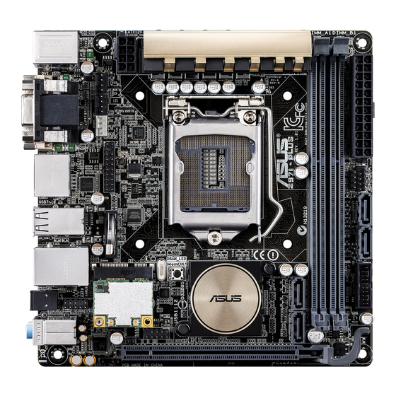
Page 21: Motherboard Layout
WIFI_LED DRAM_LED MemOK! LAN_USB3_34 WLAN Intel ® AAFP SPDIFO 64Mb BIOS Intel I218V AUDIO CLRTC USB1112 PCIEX16 SPDIF_OUT Refer to 1.2.9 Internal connectors and 2.2.1 Rear I/O connection for more information about rear panel connectors and internal connectors. ASUS Z97I-PLUS... -
Page 22: Central Processing Unit (Cpu)
The motherboard comes with a surface mount LGA1150 socket designed for the 4th ® Generation, New 4th Generation and 5th Generation Intel Core™ i7 / Core™ i5 / Core™ i3, Pentium™, and Celeron™ processors. Z97I-PLUS CPU socket LGA1150 Chapter 1: Product introduction... -
Page 23: System Memory
Contact your retailer immediately if the PnP cap is missing, or if you see any damage to the PnP cap/socket contacts/motherboard components. ASUS will shoulder the cost of repair only if the damage is shipment/ transit-related. - Page 24 Memory configurations You may install 2GB, 4GB, and 8GB unbuffered and non-ECC DDR3 DIMMs into the DIMM sockets. memory from the higher-sized channel is then mapped for single-channel operation. the CPU. recommend that you obtain memory modules from the same vendor. ®...
-
Page 25: Expansion Slots
– – – – – – shared Intel EHCI 2 shared – – – – – – – Wi-Fi – – – shared – – – – HD Audio – – – – – – shared – ASUS Z97I-PLUS 1-11... -
Page 26: Headers
Normal Clear CMOS Values (Open) (Short) Z97I-PLUS Clear CMOS jumper To erase the RTC RAM: Turn OFF the computer and unplug the power cord. Use a metal object such as a screwdriver to short the two pins. Plug the power cord and turn ON the computer. -
Page 27: Onboard Buttons And Switches
5–10 seconds. to boot and load the BIOS default settings. A message will appear during POST reminding you that the BIOS has been restored to its default settings. ASUS website at www.asus.com after using the MemOK! function. ASUS Z97I-PLUS 1-13... -
Page 28: Onboard Leds
The illustration below shows the location of the onboard LED. SB_PWR Z97I-PLUS Standby power LED DRAM LED DRAM LED checks the DRAM in sequence during motherboard booting process. If an error is found , the LED next to the error device will continue lighting until the problem is solved. -
Page 29: Internal Connectors
RSATA_RXN4 RSATA_RXP2 RSATA_RXP4 Z97I-PLUS SATA 6.0Gb/s connectors AHCI] by default. If you intend to create a Serial ATA RAID set using these connectors, set the SATA Mode Selection item in the BIOS to RAID]. Refer to section 3.6.3 PCH Storage Configuration for details. - Page 30 IntA_P2_SSTX+ IntA_P1_D- IntA_P2_D- IntA_P1_D+ IntA_P2_D+ Z97I-PLUS USB3.0 connector ® related driver to fully use the USB 3.0 ports under Windows operating system’s setting. USB 2.0 connector (10-1 pin USB1112) This connector is for USB 2.0 ports. Connect the USB module cable to this connector, then install the module to a slot opening at the back of the system chassis.
- Page 31 PWM, go to Advanced Mode > Monitor > Chassis Fan 1/2 Q-Fan Control items in BIOS. Speaker connector (4- pin SPEAKER) This 4-pin connector is for the chassis-mounted system warning speaker. The speaker allows you to hear system beeps and warnings. SPEAKER Speaker Out PIN 1 Z97I-PLUS Speaker out connector ASUS Z97I-PLUS 1-17...
- Page 32 I/O module cable to this connector. AAFP PIN 1 PIN 1 HD-audio-compliant Legacy AC’97 pin definition compliant definition Z97I-PLUS Front panel audio connector HD Audio AC97]. M.2 Socket 3 This socket allows you to install an M.2 (NGFF) module. M.2 (SOCKET3) Z97I-PLUS M.2 socket ®...
- Page 33 The system may become unstable or may not boot up if the power is inadequate. refer to the Recommended Power Supply Wattage Calculator at http://support.asus. com/PowerSupplyCalculator/PSCalculator.aspx?SLanguage=en-us for details. TPM connector (20-1 pin TPM) This connector supports a Trusted Platform Module (TPM) system, which securely network security, protect digital identities, and ensures platform integrity.
- Page 34 PWR_LED- HDD_LED+ PWR_LED+ PIN 1 Z97I-PLUS System panel connector Q-Connector This 2-pin connector is for the system power LED. Connect the chassis power LED cable to this connector. The system power LED lights up when you turn on the system power, and blinks when the system is in sleep mode.
-
Page 35: Chapter 2: Basic Installation
Remove the bolt from the Wi-Fi antenna connector but leave the washer on the washer connector. bolt bolt washer Insert the connector into the Q-shield’s Wi-Fi port hole. ASUS Z97I-PLUS... - Page 36 Replace the bolt on the connector to secure the antenna connector and the Q-shield in place. Install the ASUS Q-shield to the chassis rear I/O panel. Place the motherboard into the chassis, ensuring that its rear I/O ports are aligned to the chassis’...
- Page 37 Place four screws into the holes indicated by circles to secure the motherboard to the chassis. DO NOT overtighten the screws! Doing so can damage the motherboard. ASUS Z97I-PLUS...
- Page 38 Connect the Wi-Fi antenna cable to the Wi-Fi module properly. Chapter 2: Basic installation...
-
Page 39: Cpu Installation
2.1.2 CPU installation Ensure that you install the correct CPU designed for LGA1150 socket only. DO NOT install a CPU designed for LGA1155 and LGA1156 socket on the LGA1150 socket. ASUS Z97I-PLUS... -
Page 40: Cpu Heatsink And Fan Assembly Installation
2.1.3 CPU heatsink and fan assembly installation Apply the Thermal Interface Material to the CPU heatsink and CPU before you install the heatsink and fan, if necessary. To install the CPU heatsink and fan assembly Chapter 2: Basic installation... - Page 41 To uninstall the CPU heatsink and fan assembly ASUS Z97I-PLUS...
-
Page 42: Dimm Installation
2.1.4 DIMM installation To remove a DIMM Chapter 2: Basic installation... -
Page 43: Atx Power Connection
2.1.5 ATX Power connection ASUS Z97I-PLUS... -
Page 44: Sata Device Connection
2.1.6 SATA device connection 2-10 Chapter 2: Basic installation... -
Page 45: Front I/O Connector
2.1.7 Front I/O Connector To install the system panel connector To install USB 2.0 connector To install front panel audio connector AAFP USB 2.0 To install USB 3.0 connector USB 3.0 ASUS Z97I-PLUS 2-11... -
Page 46: Expansion Card Installation
2.1.8 Expansion Card installation To install PCIe x16 cards 2-12 Chapter 2: Basic installation...