Table of Contents
Advertisement
Advertisement
Table of Contents

Related Manuals for Asus Z97-E/USB3.1


Summary of Contents for Asus Z97-E/USB3.1
- Page 1 Z97-E/USB 3.1...
- Page 2 Product warranty or service will not be extended if: (1) the product is repaired, modified or altered, unless such repair, modification of alteration is authorized in writing by ASUS; or (2) the serial number of the product is defaced or missing.
-
Page 3: Table Of Contents
My Favorites ................2-15 Main menu .................. 2-17 Ai Tweaker menu ................ 2-19 Advanced menu ................. 2-30 Monitor menu ................2-40 Boot menu .................. 2-44 Tool menu ................... 2-50 2.10 Exit menu ..................2-51 Appendices Notices .......................A-1 ASUS contact information ...............A-4... -
Page 4: Safety Information
Safety information Electrical safety • To prevent electrical shock hazard, disconnect the power cable from the electrical outlet before relocating the system. • When adding or removing devices to or from the system, ensure that the power cables for the devices are unplugged before the signal cables are connected. If possible, disconnect all power cables from the existing system before you add a device. -
Page 5: Conventions Used In This Guide
Refer to the following sources for additional information and for product and software updates. ASUS websites The ASUS website provides updated information on ASUS hardware and software products. Refer to the ASUS contact information. Optional documentation Your product package may include optional documentation, such as warranty flyers, that may have been added by your dealer. -
Page 6: Package Contents
* Hyper DIMM support is subject to the physical characteristics of individual CPUs. Please refer to Memory QVL (Qualified Vendors List) for details. ** Refer to www.asus.com for the Memory QVL (Qualified Vendors List). 2 x PCI Express 3.0/2.0 x16 slots (single at x16 mode or dual at x8/x8 mode) Expansion 3 x PCI Express 2.0 x1 slots... - Page 7 - ASUS DIGI+ VRM - 6 Phase digital power design - ASUS Enhanced DRAM Overcurrent Protection - Short circuit damage prevention - ASUS ESD Guards - Enhanced ESD protection - ASUS High-Quality 5K-Hour Solid Capacitors - 2.5x long lifespan with excellent durability ASUS...
- Page 8 ASUS Quiet Thermal - ASUS Fan Xpert 3 Solution - ASUS Stylish Fanless Design: PCH Heat-sink & MOS Heatsink solution Precision Tweaker 2 - vCore: Adjustable CPU Core voltage at 0.001V increment - iGPU: Adjustable CPU Graphics voltage at 0.001V increment - vCCIO: Adjustable Analog and Digital I/O voltage at 0.001V increment...
- Page 9 CPU fan installed and switches to the control mode automatically. 64 Mb Flash ROM, UEFI AMI BIOS, PnP, DMI2.7, WfM2.0, SM BIOS 2.8, ACPI 5.0, Multi-language BIOS, ASUS EZ Flash 2, CrashFree BIOS 3, F6 Qfan Control, F11 EZ Tuning Wizard, F3 My Favorites & Shortcut, Quick Note,...
-
Page 11: Chapter 1: Product Introduction
• Unplug the power cord from the wall socket before touching any component. • Before handling components, use a grounded wrist strap or touch a safely grounded object or a metal object, such as the power supply case, to avoid damaging them due to static electricity. • Hold components by the edges to avoid touching the ICs on them. • Whenever you uninstall any component, place it on a grounded antistatic pad or in the bag that came with the component. • Before you install or remove any component, ensure that the ATX power supply is switched off or the power cord is detached from the power supply. Failure to do so may cause severe damage to the motherboard, peripherals, or components. ASUS Z97-E/USB 3.1... -
Page 12: Motherboard Overview
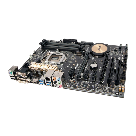
Motherboard overview Before you install the motherboard, study the configuration of your chassis to ensure that the motherboard fits. Unplug the power cord before installing or removing the motherboard. Failure to do so can cause you physical injury and damage to motherboard components. 1.2.1 Placement direction When installing the motherboard, place it into the chassis in the correct orientation. The edge with external ports goes to the rear part of the chassis as indicated in the image. 1.2.2 Screw holes Place six screws into the holes indicated by circles to secure the motherboard to the chassis. Do not overtighten the screws! Doing so can damage the motherboard. -
Page 13: Motherboard Layout
LGA1150 USB3.1_E12 LAN_USB3_34 1142 AUDIO CHA_FAN1 PCIEX1_1 Z97-E/USB 3.1 Intel ® I218-V PCIEX16_1 PCIEX1_2 Intel ® 1083 BATTERY PCIEX1_3 PCIEX16_2 Super 64Mb PCI1 BIOS PCI2 SATA6G_1 SATA6G_3 CLRTC SB_PWR USB910 USB1112 USB1314 SATA6G_2 SATA6G_4 SPDIF_OUT PANEL AAFP ASUS Z97-E/USB 3.1... -
Page 14: Central Processing Unit (Cpu)
1.2.4 Layout contents Connectors/Jumpers/Slots/LED Page 1. CPU and chassis fan connectors (4-pin CPU_FAN, 4-pin CHA_FAN1, 4-pin 1-17 CHA_FAN2, 4-pin CHA_FAN3) 2. ATX power connectors (24-pin EATXPWR, 8-pin EATX12V) 1-18 3. Intel LGA1150 CPU socket ® 4. M.2 Socket 3 1-21 5. DDR3 DIMM slots 6. USB 3.0 connector (20-1 pin USB3_12) 1-20 7. Intel Z97 Serial ATA 6.0 Gb/s connector (7-pin SATA6G_5, SATA6G_6, ® 1-22 SATAEXPRESS) 8. Intel Z97 Serial ATA 6.0 Gb/s connectors (7-pin SATA6G_1~4) 1-21 ® 9. Clear RTC RAM (2-pin CLRTC) 1-13 10. -
Page 15: Installing The Cpu
Unplug all power cables before installing the CPU. • Ensure that you install the correct CPU designed for the LGA1150 socket only. DO NOT install a CPU designed for LGA1155 and LGA1156 sockets on the LGA1150 socket. • Upon purchase of the motherboard, ensure that the PnP cap is on the socket and the socket contacts are not bent. Contact your retailer immediately if the PnP cap is missing, or if you see any damage to the PnP cap/socket contacts/motherboard components. • Keep the cap after installing the motherboard. ASUS will process Return Merchandise Authorization (RMA) requests only if the motherboard comes with the cap on the LGA1150 socket. • The product warranty does not cover damage to the socket contacts resulting from incorrect CPU installation/removal, or misplacement/loss/incorrect removal of the PnP cap. 1.3.1 Installing the CPU ASUS Z97-E/USB 3.1... -
Page 16: Cpu Heatsink And Fan Assembly Installation
1.3.2 CPU heatsink and fan assembly installation Apply the Thermal Interface Material to the CPU heatsink and CPU before you install the heatsink and fan if necessary. Chapter 1: Product introduction... - Page 17 To install the CPU heatsink and fan assembly To uninstall the CPU heatsink and fan assembly ASUS Z97-E/USB 3.1...
-
Page 18: System Memory
System memory 1.4.1 Overview This motherboard comes with four Double Data Rate 3 (DDR3) Dual Inline Memory Module (DIMM) sockets. A DDR3 module is notched differently from a DDR or DDR2 module. DO NOT install a DDR or DDR2 memory module to the DDR3 slot. According to Intel CPU spec, DIMM voltage below 1.65 V is recommended to protect the ® CPU. Z97-E/USB 3.1 Z97-E/USB 3.1 240-pin DDR3 DIMM sockets 1.4.2 Memory configurations You may install 2 GB, 4 GB, and 8 GB unbuffered non-ECC DDR3 DIMMs into the DIMM sockets. You can refer to the recommended memory population below. Recommended memory configurations Chapter 1: Product introduction... - Page 19 F or more details, refer to the Microsoft support site at http://support.microsoft. ® com/kb/929605/en-us. • This motherboard does not support DIMMs made up of 512 Mb (64 MB) chips or less. • The default memory operation frequency is dependent on its Serial Presence Detect (SPD), which is the standard way of accessing information from a memory module. Under the default state, some memory modules for overclocking may operate at a lower frequency than the vendor-marked value. To operate at the vendor-marked or at a higher frequency, refer to section 2.5 Ai Tweaker menu for manual memory frequency adjustment. • Memory modules with memory frequency higher than 2133MHz and their corresponding timing or the loaded XMP profile is not the JEDEC memory standard. The stability and compatibility of the memory modules depend on the CPU’s capabilities and other installed devices. • For system stability, use a more efficient memory cooling system to support a full memory load (4 DIMMs). • ASUS exclusively provides hyper DIMM support function. • Hyper DIMM support is subject to the physical characteristics of individual CPUs. Load the X.M.P. or D.O.C.P. settings in the BIOS for the hyper DIMM support. • Visit the ASUS website for the latest QVL. ASUS Z97-E/USB 3.1...
-
Page 20: Installing A Dimm
1.4.3 Installing a DIMM To remove a DIMM 1-10 Chapter 1: Product introduction... -
Page 21: Expansion Slots
Secure the card to the chassis with the screw you removed earlier. Replace the system cover. 1.5.2 Configuring an expansion card After installing the expansion card, configure it by adjusting the software settings. Turn on the system and change the necessary BIOS settings, if any. See Chapter 2 for information on BIOS setup. Assign an IRQ to the card. Install the software drivers for the expansion card. When using PCI cards on shared slots, ensure that the drivers support “Share IRQ” or that the cards do not need IRQ assignments. Otherwise, conflicts will arise between the two PCI groups, making the system unstable and the card inoperable. 1.5.3 PCI slots The PCI slot supports cards such as a LAN card, SCSI card, USB card, and other cards that comply with PCI specifications. 1.5.4 PCI Express 2.0 x1 slots This motherboard supports PCI Express x1 network cards, SCSI cards, and other cards that comply with the PCI Express specifications. 1.5.5 PCI Express 3.0/2.0 x16 slots This motherboard has two PCI Express 3.0/2.0 x16 slots that support PCI Express 3.0/2.0 x16 graphic cards complying with the PCI Express specifications. ASUS Z97-E/USB 3.1 1-11... - Page 22 PCI Express 3.0 operating mode VGA configuration PCIe 3.0/2.0 x16_1 (gray) PCIe 3.0/2.0 x16_2 x16 (Recommended for single Single VGA/PCIe card VGA card) Dual VGA/PCIe card • In single VGA card mode, use the PCIe 3.0/2.0 x16_1 slot (gray) for a PCI Express x16 graphics card to get better performance. • We recommend that you provide sufficient power when running SLI™ or CrossFireX™ mode. • Connect a chassis fan to the motherboard connector labeled CHA_FAN1/2/3 when using multiple graphics cards for better thermal environment. IRQ assignments for this motherboard I.G.D.
-
Page 23: Headers
CLRTC Z97-E/USB 3.1 PIN 1 Z97-E/USB 3.1 Clear RTC RAM To erase the RTC RAM: Turn OFF the computer and unplug the power cord. Use a metal object such as a screwdriver to short the two pins. Plug the power cord and turn ON the computer. Hold down the <Del> key during the boot process and enter BIOS setup to re- enter data. • If the steps above do not help, remove the onboard battery and short the two pins again to clear the CMOS RTC RAM data. After clearing the CMOS, reinstall the battery. • You do not need to clear the RTC when the system hangs due to overclocking. For system failure due to overclocking, use the CPU Parameter Recall (C.P.R.) feature. Shut down and reboot the system, then the BIOS automatically resets parameter settings to default values. ASUS Z97-E/USB 3.1 1-13... -
Page 24: Connectors
Connectors 1.7.1 Rear panel connectors PS/2 Mouse/Keyboard combo port. This port connects to a PS/2 mouse or PS/2 keyboard. Video Graphics Adapter (VGA) port. This 15-pin port is for a VGA monitor or other VGA-compatible devices. LAN (RJ-45) port. This port allows Gigabit connection to a Local Area Network (LAN) through a network hub. LAN port LED indications Activity Link Speed Activity/Link LED Speed LED Status Description Status Description No link 10 Mbps connection Orange Linked ORANGE 100 Mbps connection... - Page 25 9 series chipset, all USB devices connected to the ® USB 2.0 and USB 3.0 ports are controlled by the xHCI controller. Some legacy USB devices must update their firmware for better compatibility. • Multi-VGA output supports up to three displays under Windows OS environment, two ® displays under BIOS, and one display under DOS. • Intel display architecture design supports the following maximum supported pixel clocks (Pixel Clock = H total x V Total x Frame Rate (Screen refresh rate)): DVI port: 165 MHz VGA port: 180 MHz HDMI port: 300 MHz USB 3.1 ports 1 and 2. These two Universal Serial Bus (USB) ports are for USB 3.1 devices. HDMI port. This port connects to the tape, CD, DVD player, or other audio sources. DVI-D port. This port is for any DVI-D compatible device. DVI-D can not be converted to output from RGB Signal to CRT and is not compatible with DVI-I. USB 2.0 ports 7 and 8. These two 4-pin Universal Serial Bus (USB) ports are for USB 2.0/1.1 devices. ASUS Z97-E/USB 3.1 1-15...
-
Page 26: Internal Connectors
1.7.2 Internal connectors Serial port connector (10-1 pin COM) This connector is for a serial (COM) port. Connect the serial port module cable to this connector, then install the module to a slot opening at the back of the system chassis. PIN 1 Z97-E/USB 3.1 Z97-E/USB 3.1 Serial port (COM) connector The COM module is purchased separately. TPM connector (20-1 pin TPM) This connector supports a Trusted Platform Module (TPM) system, which securely store keys, digital certificates, passwords and data. A TPM system also helps enhance the network security, protects digital identities, and ensures platform integrity. PIN 1 Z97-E/USB 3.1 Z97-E/USB 3.1 TPM connector 1-16 Chapter 1: Product introduction... - Page 27 Z97-E/USB 3.1 Fan connectors Do not forget to connect the fan cables to the fan connectors. Insufficient air flow inside the system may damage the motherboard components. These are not jumpers! Do not place jumper caps on the fan connectors! The CPU_FAN connector supports a CPU fan of maximum 1 A (12 W) fan power. • The CPU_FAN connector and CHA_FAN connectors support the ASUS FAN Xpert 3 feature. • The CPU fan connector detects the type of CPU fan installed and automatically switches the control modes. To configure the CPU fan’s control mode, go to Advanced Mode > Monitor > CPU Q-Fan Control item in BIOS. • The chassis fan connectors support DC and PWM modes. To set these fans to DC or PWM, go to Advanced Mode > Monitor > Chassis Fan 1/2/3 Q-Fan Control items in BIOS. ASUS Z97-E/USB 3.1 1-17...
- Page 28 +3 Volts +3 Volts PIN 1 Z97-E/USB 3.1 ATX power connectors • For a fully configured system, we recommend that you use a power supply unit (PSU) that complies with ATX 12 V Specification 2.0 (or later version) and provides a minimum power of 350 W. • DO NOT forget to connect the 4-pin/8-pin ATX +12V power plug. Otherwise, the system will not boot up. • We recommend that you use a PSU with higher power output when configuring a system with more power-consuming devices or when you intend to install additional devices. The system may become unstable or may not boot up if the power is inadequate. • If you want to use two or more high-end PCI Express x16 cards, use a PSU with 1000W power or above to ensure the system stability. • If you are uncertain about the minimum power supply requirement for your system, refer to the Recommended Power Supply Wattage Calculator at http://support.asus. com/PowerSupplyCalculator/PSCalculator.aspx?SLanguage=en-us for details. 1-18 Chapter 1: Product introduction...
-
Page 29: Front Panel Audio Connector 10-1 Pin Aafp
If you want to connect a high-definition front panel audio module to this connector, set the Front Panel Type item in the BIOS setup to [HD]. If you want to connect an AC’97 front panel audio module to this connector, set the item to [AC97]. By default, this connector is set to [HD]. See section 2.6.7 Onboard Devices Configuration for details. Digital audio connector (4-1 pin SPDIF_OUT) This connector is for an additional Sony/Philips Digital Interface (S/PDIF) port. Connect the S/PDIF Out module cable to this connector, then install the module to a slot opening at the back of the system chassis. Z97-E/USB 3.1 PIN 1 SPDIF_OUT Z97-E/USB 3.1 Digital audio connector The S/PDIF module is purchased separately. ASUS Z97-E/USB 3.1 1-19... - Page 30 USB 3.0 connector (20-1 pin USB3_12) This connector allows you to connect a USB 3.0 module for additional USB 3.0 front or rear panel ports. With an installed USB 3.0 module, you can enjoy all the benefits of USB 3.0 including faster data transfer speeds of up to 5 Gbps, faster charging time for USB-chargeable devices, optimized power efficiency, and backward compatibility with USB 2.0. USB3_12 PIN 1 USB3+5V USB3+5V IntA_P1_SSRX- IntA_P2_SSRX- IntA_P1_SSRX+ Z97-E/USB 3.1 IntA_P2_SSRX+ IntA_P1_SSTX- IntA_P2_SSTX- IntA_P1_SSTX+ IntA_P2_SSTX+ IntA_P1_D- IntA_P2_D- IntA_P1_D+ IntA_P2_D+ Z97-E/USB 3.1 USB3.0 Front panel connector The USB 3.0 module is purchased separately. • These connectors are based on xHCI specification. We recommend you to install the related driver to fully use the USB 3.0 ports under Windows ®...
- Page 31 Z97 Serial ATA 6.0Gb/s connectors (7-pin SATA6G_1~4) ® These connectors connect to Serial ATA 6.0 Gb/s hard disk drives via Serial ATA 6.0 Gb/s signal cables. If you installed Serial ATA hard disk drives, you can create a RAID 0, 1, 5, and 10 configuration with the Intel Rapid Storage Technology through the onboard Intel Z97 ® ® chipset. Z97-E/USB 3.1 Z97-E/USB 3.1 Intel SATA 6 Gb/s connectors ® • These connectors are set to [AHCI] by default. If you intend to create a Serial ATA RAID set using these connectors, set the SATA Mode item in the BIOS to [RAID]. Refer to section 2.6.3 PCH Storage Configuration for details. • Before creating a RAID set, refer to the manual bundled in the motherboard support DVD. ASUS Z97-E/USB 3.1 1-21...
- Page 32 Intel Z97 Serial ATA 6.0Gb/s connector (7-pin SATA6G_5, SATA6G_6, ® SATAEXPRESS) These connectors connect to Serial ATA 6.0 Gb/s hard disk drives via Serial ATA 6.0 Gb/s signal cables. If you installed Serial ATA hard disk drives, you can create a RAID 0, 1, 5, and 10 configuration with the Intel Rapid Storage Technology through the onboard Intel Z97 ® ® chipset. SATA6G_5 SATA6G_6 RSATA_TXP5 RSATA_TXN5 RSATA_RXN5 RSATA_RXP5 RSATA_TXP6 RSATA_TXN6 RSATA_RXN6 Z97-E/USB 3.1 RSATA_RXP6 Floating Device_Reset Detection SATAEXPRESS Z97-E/USB 3.1 Intel SATA 6 Gb/s connectors ®...
-
Page 33: System Panel Connector
Pressing the power switch for more than four seconds while the system is ON turns the system OFF. • Reset button (2-pin RESET) This 2-pin connector is for the chassis-mounted reset button for system reboot without turning off the system power. ASUS Z97-E/USB 3.1 1-23... -
Page 34: Onboard Leds
Onboard LEDs Standby Power LED (SB_PWR) The motherboard comes with a standby power LED that lights up to indicate that the system is ON, in sleep mode, or in soft-off mode. This is a reminder that you should shut down the system and unplug the power cable before removing or plugging in any motherboard component. The illustration below shows the location of the onboard LED. Z97-E/USB 3.1 SB_PWR Standby Power Powered Off Z97-E/USB 3.1 Standby power LED 1-24 Chapter 1: Product introduction... -
Page 35: Software Support
To run the Support DVD Place the Support DVD into the optical drive. If Autorun is enabled in your computer, the DVD automatically displays the lists of the unique features of your ASUS motherboard. Click the Drivers, Utilities, AHCI/RAID Driver, Manual, Contact, or Specials tabs to display their respective menus. The following screen is for reference only. Click an icon to display Support DVD/motherboard information Click an item to install If Autorun is NOT enabled in your computer, browse the contents of the Support DVD to locate the file ASSETUP.EXE from the BIN folder. Double-click the ASSETUP.EXE to run the DVD. ASUS Z97-E/USB 3.1 1-25... - Page 36 1-26 Chapter 1: Product introduction...
-
Page 37: Chapter 2: Bios Information
Managing and updating your BIOS Save a copy of the original motherboard BIOS file to a USB flash disk in case you need to restore the BIOS in the future. Copy the original motherboard BIOS using the ASUS Update utility. -
Page 38: Asus Ez Flash 2
2.1.2 ASUS EZ Flash 2 The ASUS EZ Flash 2 feature allows you to update the BIOS without using an OS‑based utility. Before you start using this utility, download the latest BIOS file from the ASUS website at www.asus.com. To update the BIOS using EZ Flash 2: Insert the USB flash disk that contains the latest BIOS file to the USB port. -
Page 39: Asus Crashfree Bios 3 Utility
2.1.3 ASUS CrashFree BIOS 3 utility The ASUS CrashFree BIOS 3 is an auto recovery tool that allows you to restore the BIOS file when it fails or gets corrupted during the updating process. You can restore a corrupted BIOS file using the motherboard support DVD or a USB flash drive that contains the updated BIOS file. - Page 40 ENTER to select boot device ESC to boot using defaults P2: ST3808110AS (76319MB) aigo miniking (250MB) UEFI: (FAT) ASUS DRW-2014L1T(4458MB) P1: ASUS DRW-2014L1T(4458MB) UEFI: (FAT) aigo miniking (250MB) Enter Setup When the booting message appears, press <Enter> within five (5) seconds to enter FreeDOS prompt.
- Page 41 DO NOT shut down or reset the system while updating the BIOS to prevent system boot failaure. Ensure to load the BIOS default settings to ensure system compatibility and stability. Select the Load Optimized Defaults item under the Exit BIOS menu. See section 2.10 Exit Menu for details. ASUS Z97-E/USB 3.1...
-
Page 42: Bios Setup Program
The BIOS setup screens shown in this section are for reference purposes only, and may not exactly match what you see on your screen. • Visit the ASUS website at www.asus.com to download the latest BIOS file for this motherboard. •... - Page 43 Click the button to manually Saves the changes Selects the boot tune the fans and resets the device priority system Loads optimized default settings The boot device options vary depending on the devices you installed to the system. ASUS Z97-E/USB 3.1 2‑7...
-
Page 44: Advanced Mode
2.2.2 Advanced Mode The Advanced Mode provides advanced options for experienced end‑users to configure the BIOS settings. The figure below shows an example of the Advanced Mode. Refer to the following sections for the detailed configurations. To access the EZ Mode, click EzMode(F7) or press <F7>. Q-Fan control EZ Tuning Wizard... -
Page 45: Menu Bar
This button above the menu bar allows you to view and tweak the overclocking settings of your system. It also allows you to change the motherboard’s SATA mode from AHCI to RAID mode. Refer to section 2.2.4 EZ Tuning Wizard for more information. ASUS Z97-E/USB 3.1... -
Page 46: Hot Keys
Quick Note (F9) This button above the menu bar allows you to key in notes of the activities that you have done in BIOS. • The Quick Note function does not support the following keyboard functions: delete, cut, copy and paste. •... -
Page 47: Qfan Control
Click to activate DC Click to activate to be configured Mode PWM Mode Select a profile to apply Click to apply to your fans the fan setting Click to undo Click to the changes go back to main menu ASUS Z97-E/USB 3.1 2-11... - Page 48 Configuring fans manually Select Manual from the list of profiles to manually configure your fans’ operating speed. Click to manually Speed points configure your fans To configure your fans: Select the fan that you want to configure and to view its current status. Click and drag the speed points to adjust the fans’...
-
Page 49: Ez Tuning Wizard
Select the CPU fan type (Box cooler, Tower cooler, or Water cooler) that you installed then click Next. If you are not sure of the CPU fan type, click I’m not sure. The system automatically detects the CPU fan type. Click Next then click Yes to confirm auto‑tuning. ASUS Z97-E/USB 3.1 2‑13... -
Page 50: Creating Raid
Creating RAID To create RAID: Press <F11> on your keyboard or click from the BIOS screen to open EZ Tuning Wizard screen. Click RAID then click Next. • Ensure that your HDDs have no existing RAID volumes. • Ensure to connect your HDDs to Intel SATA connectors. -
Page 51: My Favorites
My Favorites MyFavorites is your personal space where you can easily save and access your favorite BIOS items. ASUS Z97-E/USB 3.1 2-15... - Page 52 Adding items to My Favorites To add BIOS items: Press <F3> on your keyboard or click from the BIOS screen to open Setup Tree Map screen. On the Setup Tree Map screen, select the BIOS items that you want to save in MyFavorites screen.
-
Page 53: Main Menu
If you have set an administrator password, we recommend that you enter the administrator password for accessing the system. Otherwise, you might be able to see or change only selected fields in the BIOS setup program. ASUS Z97-E/USB 3.1 2‑17... -
Page 54: User Password
To set an administrator password: Select the Administrator Password item and press <Enter>. From the Create New Password box, key in a password, then press <Enter>. Confirm the password when prompted. To change an administrator password: Select the Administrator Password item and press <Enter>. From the Enter Current Password box, key in the current password, then press <Enter>. -
Page 55: Ai Tweaker Menu
The following three items appear only when you set the Ai Overclocking Tuner to [Manual]. Filter PLL [Auto] Set this item to high BCLK (base clock) mode when using a very high BCLK to improve overclocking capability. Configuration options: [Auto] [Low BCLK Mode] [High BCLK Mode] ASUS Z97-E/USB 3.1 2-19... - Page 56 BCLK Frequency. 2.5.2 ASUS MultiCore Enhancement [Auto] [Auto] This item allows you to maximize the oveclocking performance optimized by ASUS core ratio settings. [Disabled] This item allows you to set to default core ratio settings. 2.5.3 CPU Core Ratio [Auto] This item allows you to set the CPU core ratio limit per core or synchronize automatically to all cores.
- Page 57 This item allows you to automatically overclock the CPU and DRAM frequencies and voltage for an enhanced system performance. It also accelerates the CPU graphics performance to the extreme depending on the CPU graphics loading. Configuration options: [Keep Current Settings] [Ratio Tuning] [BCLK + Ratio Tuning] ASUS Z97-E/USB 3.1 2-21...
-
Page 58: Dram Timing Control
2.5.12 EPU Power Saving Mode [Disabled] ASUS EPU (Energy Processing Unit) sets the CPU in its minimum power consumption settings. Enable this item to set lower CPU VCCIN and Vcore voltages and achieve the best energy saving condition. Configuration options: [Disabled] [Enabled] 2.5.13... - Page 59 Also known as Power Limit 1, this item allows you to maintain the time window for Turbo Ratio over TDP (Thermal Design Power). Use the <+> or <‑> keys to adjust the value. The values range from 1 to 127 in seconds. ASUS Z97-E/USB 3.1 2‑23...
- Page 60 Short Duration Package Power Limit [Auto] Also known as Power Limit 2, this item allows you to provide rapid protection when the package power exceeds the Power Limit 1. Use the <+> or <‑> keys to adjust the value. The values range from 1 W to 4096 W. CPU Integrated VR Current Limit [Auto] Allows you to set a higher current limit to prevent frequency and power throttling when overclocking.
- Page 61 [Adaptive Mode] is available for some specific CPU types. CPU Core Voltage Override [Auto] Allows you to set the CPU Core Voltage override. Use the <+> or <‑> keys to adjust the value. The values range from 0.001V to 1.920V with a 0.001V interval. ASUS Z97-E/USB 3.1 2-25...
- Page 62 The following items appear only when you set the CPU Core Voltage to [Offset Mode] or [Adaptive Mode]. Offset Mode Sign [+] To offset the voltage by a positive value. [–] To offset the voltage by a negative value. CPU Core Voltage Offset Use the <+>...
- Page 63 0.001V to 1.920V with a 0.001V interval. Total Adaptive Mode CPU Graphics Voltage [Auto] This item sums up the voltages of the CPU Graphics Voltage offset and Additional Turbo Mode CPU Graphics Voltage options. ASUS Z97-E/USB 3.1 2‑27...
- Page 64 2.5.20 CPU System Agent Voltage Offset Mode Sign [+] To offset the voltage by a positive value. [–] To offset the voltage by a negative value. CPU System Agent Voltage Offset [Auto] This item allows you to set the amount of voltage fed to the system agent of the CPU including its PCIE controller and the PCU (power control unit).
- Page 65 This item allows you to enhance the BCLK overclocking capability or reduce the EMI (electromagnetic disturbance) generated by the BCLK. Set this item to [Enabled] for EMI reduction, or set this item to [Disabled] to enhance BCLK overclocking. Configuration options: [Auto] [Disabled] [Enabled] ASUS Z97-E/USB 3.1 2-29...
-
Page 66: Advanced Menu
Advanced menu The Advanced menu items allow you to change the settings for the CPU and other system devices. Be cautious when changing the settings of the Advanced menu items. Incorrect field values can cause the system to malfunction. 2.6.1 CPU Configuration The items in this menu show the CPU‑related information that the BIOS automatically detects. -
Page 67: Cpu Power Management Configuration
This item allows you to automatically set the CPU cores to run faster than the base operating frequency when it is below the operating power, current and temperature specification limit. Configuration options: [Enabled] [Disabled] Turbo Mode is only available on selected CPU models only. ASUS Z97-E/USB 3.1 2‑31... -
Page 68: Pch Configuration
CPU C-States [Auto] This item allows you to set the power saving of the CPU states. Configuration options: [Auto] [Disabled] [Enabled] The following items appear only when you set the CPU C‑States to [Enabled]. Enhanced C1 state [Enabled] This item allows your CPU to reduce power consumption when the system is in idle mode. -
Page 69: Pch Storage Configuration
The system assigns the priority bandwidth to M.2 Socket 3. By default, the system detects the first priority device. The device detection priority is as follows: PCIe M.2 > SATA Mode M.2 > PCIe SATA Express > SATA Mode SATA Express. ASUS Z97-E/USB 3.1 2‑33... -
Page 70: System Agent Configuration
The system automatically adjust the SRIS (Separate Reference Clock Independent Spread Spectrum Clocking Architecture) support for connected SATA Express devices. [Disabled] Select this option for ASUS RUNWAY SATA Express bridge card. SATA Mode Selection [AHCI] Allows you to set the SATA configuration. [Disabled] Disables the SATA function. -
Page 71: Graphics Configuration
Allows you to configure the PCIEx16 speed for slot 2. Configuration options: [Auto] [Gen1] [Gen2] [Gen3] Memory Configuration Allows you to configure the memory configuration parameters. Memory Scrambler [Enabled] Set this item to [Enabled] to support high frequency DRAMs for a better stability. Configuration options: [Enabled] [Disabled] ASUS Z97-E/USB 3.1 2‑35... -
Page 72: Usb Configuration
Memory Remap [Enabled] Set this item to [Enabled] to support DRAM address remapping for 64‑bit operating systems. Configuration options: [Enabled] [Disabled] 2.6.5 USB Configuration The items in this menu allow you to change the USB‑related features. The USB Devices item shows the auto‑detected values. If no USB device is detected, the item shows None. -
Page 73: Onboard Devices Configuration
ASPM to take effect. Configuration options: [Disabled] [L0s] [L1] [L0sL1] PEG ASPM Support [Disabled] This item allows you to select the ASPM state for energy‑saving conditions, or use the ASUS optimized energy saving profile. Configuration options: [Disabled] [Auto] [ASPM L0s] [L1] [L0sL1] 2.6.7... -
Page 74: Serial Port Configuration
SPDIF Out Type [SPDIF] [SPDIF] Sets to an SPDIF audio output. [HDMI] Sets to an HDMI audio output. Depop [Enabled] Configuration options: [Disabled] [Enabled] Audio Shielding LED [Auto] [Auto] The LED control depends on the configuration of the ErP Ready item. Set this item to [Auto] and the ErP Ready item to [Disabled] to keep the LED [Disabled] Turn off the LED. - Page 75 This item allows you to enable or disable the RTC (Real‑Time Clock) to generate a wake event and configure the RTC alarm date. When enabled, you can set the days, hours, minutes, or seconds to schedule an RTC alarm date. Configuration options: [Disabled] [Enabled] ASUS Z97-E/USB 3.1 2‑39...
-
Page 76: Monitor Menu
2.6.9 Network Stack Configuration Network Stack [Disabled] This item allows user to disable or enable the UEFI network stack. Configuration options: [Disabled] [Enabled] The following two items appear only when you set the previous item to [Enabled]. Ipv4 / Ipv6 PXE Support [Enabled] This item allows you to enable or disable the Ipv4/Ipv6 PXE wake event. - Page 77 The following four items appear only when you set CPU Fan Profile to [Manual]. CPU Upper Temperature [70] Use the <+> and <‑> keys to adjust the upper limit of the CPU temperature. The values range from 25ºC to 75ºC. ASUS Z97-E/USB 3.1 2-41...
- Page 78 CPU Fan Max. Duty Cycle(%) [100] Use the <+> and <‑> keys to adjust the maximum CPU fan duty cycle. The values range from 20% to 100%. When the CPU temperature reaches the upper limit, the CPU fan will operate at the maximum duty cycle. CPU Middle Temperature [25] Use the <+>...
- Page 79 Allow Fan Stop [Disabled] This item allows you to enable to disable fan stop. Configuration options: [Enabled] [Disabled] 2.7.7 Anti Surge Support [Enabled] This item allows you to enable or disable the Anti Surge function. Configuration options: [Disabled] [Enabled] ASUS Z97-E/USB 3.1 2‑43...
-
Page 80: Boot Menu
Boot menu The Boot menu items allow you to change the system boot options. Scroll down to display the other BIOS items. 2.8.1 Fast Boot [Enabled] [Enabled] Select to accelerate the boot speed. [Disabled] Select to go back to normal boot speed. SATA Support [All Devices] [All Devices] All devices connected to SATA ports are available during POST. - Page 81 This item allows you to enable or disable power‑on state of the NumLock. Configuration options: [Disabled] [Enabled] 2.8.4 Wait for ‘F1’ If Error [Enabled] When this item is set to [Enabled], the system waits for the F1 key to be pressed when error occurs. Configuration options: [Disabled] [Enabled] ASUS Z97-E/USB 3.1 2-45...
- Page 82 Option ROM Messages [Enabled] [Enabled] The third‑party ROM messages will be displayed during POST. [Disabled] Disables the ROM messages and displays only the ASUS logo during POST. 2.8.6 Interrupt 19 Capture [Disabled] This item allows you to trap Interrupt 19 by the option ROMs. Configuration options: [Disabled] [Enabled] 2.8.7...
-
Page 83: Secure Boot
Select Yes to load the system default PK or select No to load a downloaded PK from a USB storage device. The PK file must be formatted as a UEFI variable structure with time‑based authenticated variable. ASUS Z97-E/USB 3.1 2‑47... - Page 84 KEK Management The KEK (Key‑exchange Key or Key Enrollment Key) manages the Signature database (db) and Revoked Signature database (dbx). Key‑exchange Key (KEK) refers to Microsoft Secure Boot Key‑Enrollment Key (KEK). ® Delete KEK Allows you to delete the KEK from your system. Once the KEK is deleted, the db and the dbx cannot be updated in the operating system.
-
Page 85: Boot Option Priorities
OS in Safe Mode, press <F8 > after POST (Windows 8 not supported). • To select the boot device during system startup, press <F8> when ASUS Logo appears. 2.8.12 Boot Override These items displays the available devices. The number of device items that appears on the screen depends on the number of devices installed in the system. -
Page 86: Tool Menu
<Enter> to display the submenu. 2.9.1 ASUS EZ Flash 2 Utility Allows you to run ASUS EZ Flash 2. Press [Enter] to launch the ASUS EZ Flash 2 screen. For more details, see section 2.1.2 ASUS EZ Flash 2. 2.9.2 Setup Animator [Enabled] Enables or disables the Setup animator. -
Page 87: Exit Menu
2.9.4 ASUS SPD Information DIMM Slot number [DIMM_A1] Displays the Serial Presence Detect (SPD) information of the DIMM module installed on the selected slot. Configuration options: [DIMM_A1] [DIMM_B1] [DIMM_A2] [DIMM_B2] 2.10 Exit menu The Exit menu items allow you to load the optimal default values for the BIOS items, and save or discard your changes to the BIOS items. - Page 88 2-52 Chapter 2: Getting started...
-
Page 89: Appendices
Cet appareil est conforme aux normes CNR exemptes de licence d’Industrie Canada. Le fonctionnement est soumis aux deux conditions suivantes : (1) cet appareil ne doit pas provoquer d’interférences et (2) cet appareil doit accepter toute interférence, y compris celles susceptibles de provoquer un fonctionnement non souhaité de l’appareil. ASUS Z97-E/USB 3.1... -
Page 90: Canadian Department Of Communications Statement
ASUS Recycling/Takeback Services ASUS recycling and takeback programs come from our commitment to the highest standards for protecting our environment. We believe in providing solutions for you to be able to responsibly recycle our products, batteries, other components as well as the packaging materials. - Page 91 CE. de la CE. Consulte la Declaración de conformidad de la CE para obtener más detalles. Компания ASUS заявляет, что это устройство соответствует основным требованиям и другим соответствующим условиям европейских директив. Svenska AsusTek Inc. förklarar härmed att denna enhet är i Подробную...
-
Page 92: Asus Contact Information
+1-510-739-3777 +1-510-608-4555 Web site http://www.asus.com/us/ Technical Support Support fax +1-812-284-0883 General support +1-812-282-2787 Online support http://www.service.asus.com/ ASUS COMPUTER GmbH (Germany and Austria) Address Harkort Str. 21-23, D-40880 Ratingen, Germany +49-2102-959931 Web site http://www.asus.com/de Online contact http://eu-rma.asus.com/sales Technical Support Telephone +49-2102-5789555... - Page 93 ASUS Z97-E/USB 3.1...
- Page 94 Appendices...