Table of Contents
Advertisement
Advertisement
Table of Contents

Related Manuals for Asus Z97-WS


Summary of Contents for Asus Z97-WS
- Page 1 Z97-WS...
- Page 2 Product warranty or service will not be extended if: (1) the product is repaired, modified or altered, unless such repair, modification of alteration is authorized in writing by ASUS; or (2) the serial number of the product is defaced or missing.
-
Page 3: Table Of Contents
Contents Safety information ...................... vi About this guide ......................vii Z97-WS specifications summary ................ix Package contents ...................... xv Installation tools and components ................. xvi Chapter 1: Product Introduction Special features..................1-1 1.1.1 Product highlights................ 1-1 1.1.2 ASUS-exclusive workstation features ......... 1-2 1.1.3... - Page 4 3.6.9 Network Stack Configuration............. 3-45 Monitor menu ................... 3-46 Boot menu ....................3-50 Tool menu ....................3-56 3.9.1 ASUS EZ Flash 2 Utility ............3-56 3.9.2 ASUS O.C. Profile ..............3-57 3.9.3 ASUS DRAM SPD Information ..........3-58 3.10 Exit menu ....................3-59 3.11...
- Page 5 4.4.5 USB Charger+ ................4-13 4.4.6 Push Notice ................4-14 4.4.7 System Information ..............4-17 Audio configurations ................4-18 ASUS Dr. Power Utility ................4-20 Chapter 5: RAID support RAID configurations .................. 5-1 5.1.1 RAID definitions ................5-1 5.1.2 Installing Serial ATA hard disks ..........5-2 5.1.3...
-
Page 6: Safety Information
Safety information Electrical safety • To prevent electrical shock hazard, disconnect the power cable from the electrical outlet before relocating the system. • When adding or removing devices to or from the system, ensure that the power cables for the devices are unplugged before the signal cables are connected. If possible, disconnect all power cables from the existing system before you add a device. -
Page 7: About This Guide
Refer to the following sources for additional information and for product and software updates. ASUS website The ASUS website (www.asus.com) provides updated information on ASUS hardware and software products. Optional documentation Your product package may include optional documentation, such as warranty flyers, that may have been added by your dealer. -
Page 8: Conventions Used In This Guide
Conventions used in this guide To ensure that you perform certain tasks properly, take note of the following symbols used throughout this manual. DANGER/WARNING: Information to prevent injury to yourself when trying to complete a task. CAUTION: Information to prevent damage to the components when trying to complete a task IMPORTANT: Instructions that you MUST follow to complete a task. -
Page 9: Z97-Ws Specifications Summary
Z97-WS specifications summary LGA1150 socket for the 4th Generation and New 4th Generation Intel ® Core™ i7/Intel Core™ i5/ Intel Core™ i3, Pentium and Celeron ® ® ® ® processors Supports Intel Turbo Boost Technology 2.0* ® * The Intel Turbo Boost Technology 2.0 support depends on the CPU types. - Page 10 - Supports jack-detection, multi-streaming and front panel jack- retasking - Optical S/PDIF out ports at rear I/O Intel Z97 Express Chipset - supports ASUS USB 3.0 ® Boost - 4 x USB 3.0/2.0 ports at rear panel (blue) - 1 x USB 3.0/2.0 ports at mid-board for front panel support - 2 x USB 2.0/1.1 ports at rear panel...
- Page 11 DIGI+ Power Control CPU Power - Industry leading digital 8-phase power design - ASUS CPU power utility DRAM Power - Industry leading digital 2-phase DRAM power design - ASUS DRAM power utility...
- Page 12 - ASUS CrashFree BIOS 3 - ASUS EZ Flash 2 Q-Design - ASUS Q-Code - ASUS Q-Shield - ASUS Q-LED (CPU, DRAM, VGA, Boot Device LED) - ASUS Q-Slot - ASUS Q-DIMM - ASUS Q-Connector USB 3.0 Boost ASUS Special Features...
- Page 13 Z97-WS specifications summary Quiet Thermal Design ASUS Quiet Thermal Solution - ASUS Fan Xpert 3 - ASUS Fanless Design: Heat-pipe solution ASUS Exclusive Precision Tweaker 2 Overclocking Features - vCore: Adjustable CPU Core voltage at 0.001 V increment - iGPU: Adjustable CPU Graphics voltage at 0.001 V increment - vCCIO: Adjustable Analog and Digital I/O voltage at 0.001 V...
- Page 14 64 Mb Flash ROM, UEFI AMI BIOS, PnP, DMI 2.7, WfM 2.0, SM BIOS features BIOS 2.7, ACPI 5.0, Multi-language BIOS, ASUS EZ Flash 2, CrashFree BIOS 3, F11 EZ Tuning Wizard, F6 Qfan Control, F3 My Favorites, Quick Note, Last Modified Log, F12 PrintScreen function,...
-
Page 15: Package Contents
Support DVD 8 x Serial ATA 6 Gb/s cables COM port bracket 1 x ASUS SLI™ bridge connector 1 x ASUS 4-Way SLI™ bridge connector 1 x ASUS 3-Way SLI™ bridge 1 x 2-in-1 Q-connector connector 1 x I/O Shield... -
Page 16: Installation Tools And Components
Installation tools and components Intel ® LGA1150 CPU Intel LGA1150 compatible CPU Fan ® Philips (cross) screwdriver SATA hard disk drive PC chassis DIMM 1 bag of screws Power supply unit SATA optical disc drive (optional) Graphics card The tools and components in the table above are not included in the motherboard package. -
Page 17: Chapter 1: Product Introduction
SATA Express provides faster data transfer speeds of up to 6 Gb/s, allowing your system to catch up with the speed of the SSDs. It also features backward compatibility with up to two SATA drives of the same speed. Z97-WS... -
Page 18: Asus-Exclusive Workstation Features
If a workstation is behaving abnormally, plug a flash drive into the adjacent USB port, press the motherboard’s dedicated Flash Log button and all ASUS Q-Code event logs for the current live session will be copied to the drive. -
Page 19: Other Special Features
Beat Thermal Chokes ASUS Beat Thermal Chokes deliver great durability, minimal power loss, and up to 93% power efficiency under normal operation. A special fin design results in 3-5 C lower choke temperatures for added stability, which is increased exponentially by use of highly conductive and efficient gold-treated coating. -
Page 20: Motherboard Overview
Motherboard overview 1.2.1 Before you proceed Take note of the following precautions before you install motherboard components or change any motherboard settings. • Unplug the power cord from the wall socket before touching any component. • Before handling components, use a grounded wrist strap or touch a safely grounded object or a metal object, such as the power supply case, to avoid damaging them due to static electricity. -
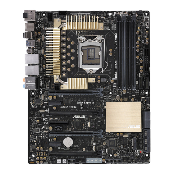
Page 21: Motherboard Layout
USB3_E56 1042AE LGA1150 LAN2_USB3_34 LAN1_USB3_12 DIAG_CPU LED AUDIO CHA_FAN1 8747 VGA_LED EATX12V_1 PCIEX16_1 210AT CHA_FAN3 PCIEX1_1 9DB433AGLF DR.Power LED Z97-WS DR_POWER Intel PCIEX16_2 ® 218LM PCIEX4_1 BIOS 1187e TB_HEADER PCIEX16_3 Super Lithium Cell 106SE PCIEX1_2 CMOS Power VIA 1394 6315N... -
Page 22: Layout Contents
9. EZ XMP switch 10. M.2 Socket 3 11. USB 3.0 connectors (20-1 pin USB3_E12, USB3_E34) 12. Dr. Power LED 13. ASUS Dr. POWER switch 14. Intel® Serial ATA 6 Gb/s connectors (7-pin SATA6G_1/6, SATAEXPRESS_1) 15. ASMedia Serial ATA 6 Gb/s connectors (7-pin SATA6G_E3, ®... -
Page 23: Central Processing Unit (Cpu)
Contact your retailer immediately if the PnP cap is missing, or if you see any damage to the PnP cap/socket contacts/motherboard components. ASUS will shoulder the cost of repair only if the damage is shipment/ transit-related. -
Page 24: System Memory
(DIMM) slots. A DDR3 module is notched differently from a DDR or DDR2 module. DO NOT install a DDR or DDR2 memory module to the DDR3 slot. Z97-WS Z97-WS 240-pin DDR3 DIMM sockets Recommended memory configurations Chapter 1: Product introduction... -
Page 25: Memory Configurations
Always install the DIMMS with the same CAS Latency. For an optimum compatibility, we recommend that you install memory modules of the same version or data code (D/C) from the same vendor. Check with the vendor to get the correct memory modules. • Visit the ASUS website for the latest QVL. Z97-WS... -
Page 26: Expansion Slots
1.2.5 Expansion slots Unplug the power cord before adding or removing expansion cards. Failure to do so may cause you physical injury and damage motherboard components. PCIEX16_1 PCIEX1_1 Z97-WS PCIEX16_2 PCIEX4_1 PCIEX16_3 PCIEX1_2 PCIEX16_4 Slot No. Slot Description PCIe 3.0/2.0 x16_1 slot PCIe 2.0 x1_1 slot... - Page 27 We recommend that you provide sufficient power when running CrossFireX™ or SLI™ mode. • Connect a chassis fan to the motherboard connector labeled CHA_FAN1-4 when using multiple graphics cards for better thermal environment. • We recommend you connect an EATX 12V_1 cable when running CrossFireX and SLI. Z97-WS 1-11...
- Page 28 IRQ assignments for this motherboard PCIe x16_1 shared – – – – – – – PCIe x16_2 – shared – – – – – – PCIe x16_3 shared – – – – – – – PCIe x16_4 – shared – –...
-
Page 29: Onboard Buttons And Switches
The button also lights up when the system is plugged to a power source indicating that you should shut down the system and unplug the power cable before removing or installing any motherboard component. Z97-WS PWR_SW Z97-WS Power on button Reset button Press the reset button to reboot the system. Z97-WS RST_SW... - Page 30 BIOS default settings. A message will appear during POST reminding you that the BIOS has been restored to its default settings. • We recommend that you download and update to the latest BIOS version from www.asus.com after using the MemOK! function. Chapter 1: Product introduction 1-14...
- Page 31 (CPU Ratio Boost) (CPU BCLK Ratio Boost) Z97-WS Z97-WS TPU switch • The TPU LED (TPU_LED) near the TPU switch lights up when the TPU switch is enabled. Refer to section 1.2.8 Onboard LEDs for the exact location of the TPU LED.
- Page 32 Enable this switch when the system is powered off. Disable Enable (Default) Z97-WS Z97-WS EPU switch • The EPU LED (OLED2) near the EPU switch lights up when the EPU switch is enabled. Refer to section 1.2.8 Onboard LEDs for the exact location of the EPU LED. •...
- Page 33 Z97-WS EZ_XMP switch ASUS Dr. POWER switch This switch allows you to enable or disable the ASUS Dr. Power feature. Install the bundled ASUS Dr. Power Utility then enable this switch to allow the system to display notification messages in your Windows screen if a problem is detected with your Power Supply Unit (PSU).
-
Page 34: Jumpers
Z97-WS CPU_OV Disable Enable (default setting) Z97-WS CPU_OV setting 1.2.8 Onboard LEDs POST State LEDs The POST State LEDs provide the status of these key components during POST (Power-On-Self Test): CPU, memory modules, VGA card, and hard disk drives. If an error is found, the critical component’s LED stays lit up until the problem is solved. - Page 35 TPU LED (TPU_LED) The TPU LED lights up when the TPU switch is enabled. TPU_LED Z97-WS Z97-WS TPU LEDs EPU LED (OLED2) The EPU LED lights up when the EPU switch is enabled. OLED2 Z97-WS Z97-WS EPU LED Power LED (+12V_PWR LED) This LED lights up when you turn on the system using the Power-on button.
- Page 36 ASUS Dr. Power LED (DR_POWER LED) The ASUS Dr. Power LED near the ASUS Dr. Power switch lights up when the ASUS Dr. Power switch is on Enable. DR.POWER LED Z97-WS Z97-WS DR_POWER LED PWR_SUPPLY LED The ASUS Dr. Power LED near the EATX PWR connector lights up when the ASUS Dr.
- Page 37 Z97-WS Z97-WS XLED1 Q-Code LEDs The Q-Code LED design provides you with a 2-digit error code that displays the system status. Refer to the Q-Code table on the next page for details. Z97-WS Q_CODE1 Q_CODE2 Z97-WS Q-Code LEDs Z97-WS 1-21...
- Page 38 Q-Code table Code Description Not used Power on. Reset type detection (soft/hard). AP initialization before microcode loading System Agent initialization before microcode loading PCH initialization before microcode loading Microcode loading AP initialization after microcode loading System Agent initialization after microcode loading PCH initialization after microcode loading Cache initialization 0C –...
- Page 39 PCI Bus Hot Plug Controller Initialization PCI Bus Enumeration PCI Bus Request Resources PCI Bus Assign Resources Console Output devices connect Console input devices connect Super IO Initialization USB initialization is started USB Reset (continued on the next page) Z97-WS 1-23...
- Page 40 Code Description USB Detect USB Enable Reserved for future AMI codes 9E – 9F IDE initialization is started IDE Reset IDE Detect IDE Enable SCSI initialization is started SCSI Reset SCSI Detect SCSI Enable Setup Verifying Password Start of Setup Reserved for ASL (see ASL Status Codes section below) Setup Input Wait Reserved for ASL (see ASL Status Codes section below)
- Page 41 System is waking up from the S3 sleep state System is waking up from the S4 sleep state System has transitioned into ACPI mode. Interrupt controller is in PIC mode. System has transitioned into ACPI mode. Interrupt controller is in APIC mode. Z97-WS 1-25...
-
Page 42: Internal Connectors
Rapid Storage Technology through the onboard Intel ® ® chipset. Z97-WS Z97-WS Intel ® SATA 6.0Gb/s connectors • These connectors are set to [AHCI Mode] by default. If you intend to create a Serial ATA RAID set using these connectors, set the SATA Mode item in the BIOS to [RAID Mode]. - Page 43 This connector is for an additional Sony/Philips Digital Interface (S/PDIF) port. Connect the S/PDIF Out module cable to this connector, then install the module to a slot opening at the back of the system chassis. SPDIF_OUT Z97-WS Z97-WS Digital audio connector The S/PDIF module is purchased separately. Z97-WS 1-27...
-
Page 44: Front Panel Audio Connector
Z97-WS HD-audio-compliant Legacy AC’97 pin definition compliant definition Z97-WS Analog front panel connector • We recommend that you connect a high-definition front panel audio module to this connector to avail of the motherboard’s high-definition audio capability. • If you want to connect a high-definition or an AC’97 front panel audio module to this connector, set the Front Panel Type item in the BIOS setup to [HD Audio] or [AC97]. - Page 45 3-pin DC FAN 4-Pin Force PWM FAN (Default) Z97-WS Chassis Fan control setting TPM connector (20-1 pin TPM) This connector supports a Trusted Platform Module (TPM) system, which securely store keys, digital certificates, passwords and data. A TPM system also helps enhance network security, protect digital identities, and ensures platform integrity.
- Page 46 IntA_P1_D+ IntA_P2_D- IntA_P1_D+ IntA_P2_D+ IntA_P2_D+ Z97-WS USB3.0 connectors The USB 3.0 module is purchased separately. • These connectors are based on xHCI specification. We recommend you to install the related driver to fully use the USB 3.0 ports under Windows ®...
- Page 47 DO NOT connect a 1394 cable to the USB connectors. Doing so will damage the motherboard! You can connect the front panel USB cable to the ASUS Q-Connector (USB) first, and then install the Q-Connector (USB) to the USB connector onboard if your chassis supports front panel USB ports.
- Page 48 • The CPU_FAN connector supports the CPU fan of maximum 1A (12 W) fan power. • The CPU_FAN connector and CHA_FAN connectors support the ASUS FAN Xpert 3 feature. • The CPU fan connector detects the type of CPU fan installed and automatically switches the control modes.
-
Page 49: Atx Power Connectors
If you want to use two or more high-end PCI Express x16 cards, use a PSU with 1000W power or above to ensure the system stability. • If you are uncertain about the minimum power supply requirement for your system, refer to the Recommended Power Supply Wattage Calculator at http://support.asus. com/PowerSupplyCalculator/PSCalculator.aspx?SLanguage=en-us for details. Z97-WS 1-33... -
Page 50: System Panel Connector
Z97-WS HDD_LED PWRSW RESET Z97-WS System panel connector • System power LED (2-pin PLED) This 2-pin connector is for the system power LED. Connect the chassis power LED cable to this connector. The system power LED lights up when you turn on the system power, and blinks when the system is in sleep mode. - Page 51 DRCT Z97-WS PIN 1 Z97-WS CPU_OV setting Ensure that your chassis comes with the extra button cable that supports the DirectKey feature. Refer to the technical documentation that came with the chassis for details. Thunderbolt header (5-pin TB_HEADER) This connector is for the add-on Thunderbolt I/O card that supports Intel’s Thunderbolt...
- Page 52 This connector is for an IEEE 1394 port. Connect the IEEE 1394 module cable to this connector, then install the module to a slot opening at the back of the system chassis. Z97-WS Z97-WS IEEE 1394 connector Chapter 1: Product introduction 1-36...
- Page 53 COM1 PIN 1 Z97-WS Z97-WS Serial port (COM1) connector The COM module is purchased separately. Chassis intrusion connector (4-1 pin CHASSIS) This connector is for a chassis-mounted intrusion detection sensor or switch. Connect one end of the chassis intrusion sensor or switch cable to this connector.
- Page 54 Chapter 1: Product introduction 1-38...
-
Page 55: Chapter 2: Basic Installation
The diagrams in this section are for reference only. The motherboard layout may vary with models, but the installation steps are the same for all models. Install the ASUS Q-Shield to the chassis rear I/O panel. Place the motherboard into the chassis, ensuring that its rear I/O ports are aligned to the chassis’... - Page 56 Place nine screws into the holes indicated by circles to secure the motherboard to the chassis. Z97-WS DO NOT overtighten the screws! Doing so can damage the motherboard. Chapter 2: Basic installation...
-
Page 57: Cpu Installation
2.1.2 CPU installation Ensure that you install the correct CPU designed for LGA1150 socket only. DO NOT install a CPU designed for LGA1155 and LGA1156 sockets on the LGA1150 socket. Z97-WS... -
Page 58: Cpu Heatsink And Fan Assembly Installation
2.1.3 CPU heatsink and fan assembly installation Apply the Thermal Interface Material to the CPU heatsink and CPU before you install the heatsink and fan, if necessary. To install the CPU heatsink and fan assembly Chapter 2: Basic installation... - Page 59 To uninstall the CPU heatsink and fan assembly Z97-WS...
-
Page 60: Dimm Installation
2.1.4 DIMM installation To remove a DIMM Chapter 2: Basic installation... -
Page 61: Atx Power Connection
2.1.5 ATX Power connection Z97-WS... -
Page 62: Sata Device Connection
2.1.6 SATA device connection Chapter 2: Basic installation... -
Page 63: Front I/O Connector
2.1.7 Front I/O Connector To install ASUS Q-Connector To install USB 2.0 connector To install front panel audio connector AAFP USB 2.0 To install USB 3.0 connector USB 3.0 Z97-WS... -
Page 64: Expansion Card Installation
2.1.8 Expansion Card installation To install PCIe x16 cards To install PCIe x1 cards Chapter 2: Basic installation 2-10... -
Page 65: Bios Update Utility
Press the BIOS Flashback button at the rear panel for three seconds until the Flashback LED blinks three times, indicating that the BIOS Flashback function is enabled. USB BIOS Flashback button Refer to section 1.2.7 Onboard LEDs for more information of the Flashback LED. Z97-WS 2-11... - Page 66 • Updating BIOS may have risks. If the BIOS program is damaged during the process and results to the system’s failure to boot up, please contact your local ASUS Service Center. Q-Code Logger Q-Code Logger allows you to easily check Q-Code event logs with opening the computer’s case.
-
Page 67: Motherboard Rear And Audio Connections
Intel LAN port (LAN2)* USB 3.0 ports 1 and 2 ® Intel LAN port (LAN1)* Audio I/O ports** ® * and **: Refer to the tables on the next page for LAN port LEDs and audio port definitions. Z97-WS 2-13... - Page 68 • Only USB 3.0 ports 5 and 6 support Ai Charger+ function. • Only USB2.0 port 6 supports USB Charger+ function • The plugged USB 3.0 device may run on xHCI mode or EHCI mode, depending on the operating system’s setting. • USB 3.0 devices can only be used as data storage only. • We strongly recommend that you connect USB 3.0 devices to USB 3.0 ports for faster and better performance for your USB 3.0 devices. • Due to the design of the Intel 9 series chipset, all USB devices connected to the ® USB 2.0 and USB 3.0 ports are controlled by the xHCI controller. Some legacy USB devices must update their firmware for better compatibility.
-
Page 69: Audio I/O Connections
– Center/Subwoofer Rear Speaker Out Black – Rear Speaker Out Rear Speaker Out Side Speaker Out* Gray – – Side Speaker Out * For Windows ® 8.1 only 2.3.2 Audio I/O connections Audio I/O ports Connect to Headphone and Mic Connect to Stereo Speakers Z97-WS 2-15... - Page 70 Connect to 2.1 channel Speakers Connect to 4.1 channel Speakers Connect to 5.1 channel Speakers If you are using Windows 8.1 platform, use only the gray audio port for Side Speaker Out in a 6-channel configuration. Chapter 2: Basic installation 2-16...
-
Page 71: Starting Up For The First Time
If you do not see anything within 30 seconds from the time you turned on the power, the system may have failed a power-on test. Check the jumper settings and connections or call your retailer for assistance. Z97-WS 2-17... -
Page 72: Turning Off The Computer
BIOS Beep Description One short beep VGA detected Quick boot set to disabled No keyboard detected One continuous beep followed by two No memory detected short beeps then a pause (repeated) One continuous beep followed by three No VGA detected short beeps One continuous beep followed by four Hardware component failure... -
Page 73: Chapter 3: Bios Setup
BIOS setup Knowing BIOS The new ASUS UEFI BIOS is a Unified Extensible Interface that complies with UEFI architecture, offering a user-friendly interface that goes beyond the traditional keyboard- only BIOS controls to enable a more flexible and convenient mouse input. You can easily navigate the new UEFI BIOS with the same smoothness as your operating system. -
Page 74: Bios Setup Program
BIOS setup program Use the BIOS Setup to update the BIOS or configure its parameters. The BIOS screen include navigation keys and brief onscreen help to guide you in using the BIOS Setup program. Entering BIOS at startup To enter BIOS Setup at startup, press <Delete> during the Power-On Self Test (POST). If you do not press <Delete>, POST continues with its routines. -
Page 75: Ez Mode
Displays the CPU Fan’s speed. Click Selects the boot Saves the changes and the button to manually tune the fans device priority resets the system Loads optimized default settings The boot device options vary depending on the devices you installed to the system. Z97-WS... -
Page 76: Advanced Mode
3.2.2 Advanced Mode The Advanced Mode provides advanced options for experienced end-users to configure the BIOS settings. The figure below shows an example of the Advanced Mode. Refer to the following sections for the detailed configurations. To switch from EZ Mode to Advanced Mode, click Advanced Mode F7 or press F7 hotkey. Q-Fan control EZ Tuning Wizard MyFavorite... -
Page 77: Menu Bar
This button above the menu bar allows you to view and tweak the overclocking settings of your system. It also allows you to change the motherboard’s SATA mode from AHCI to RAID mode. Refer to section 3.2.4 EZ Tuning Wizard for more information. Z97-WS... -
Page 78: Hot Keys
Quick Note (F9) This button above the menu bar allows you to key in notes of the activities that you have done in BIOS. • The Quick Note function does not support the following keyboard functions: delete, cut, copy and paste. •... -
Page 79: Qfan Control
Click to activate DC Mode configured PWM Mode Select a profile to apply to Click to apply the fan setting your fans Click to undo the Click to go back to main menu changes Select to manually configure your fans Z97-WS... -
Page 80: Configuring Fans Manually
Configuring fans manually Select Manual from the list of profiles to manually configure your fans’ operating speed. Speed points Click or tap to manually configure your fans To configure your fans: Select the fan that you want to configure and to view its current status. Click and drag the speed points to adjust the fans’... -
Page 81: Ez Tuning Wizard
Select the CPU fan type (Box cooler, Tower cooler, or Water cooler) that you installed then click Next. If you are not sure of the CPU fan type, click I’m not sure. The system automatically detects the CPU fan type. Click Next then click Yes to confirm auto-tuning. Z97-WS... -
Page 82: Creating Raid
Creating RAID To create RAID: Press <F11> on your keyboard or click from the BIOS screen to open EZ Tuning Wizard screen. Click RAID then click Next. • Ensure that your HDDs have no existing RAID volumes. • Ensure to connect your HDDs to Intel SATA connectors. -
Page 83: My Favorites
My Favorites MyFavorites is your personal space where you can easily save and access your favorite BIOS items. Z97-WS 3-11... -
Page 84: Adding Items To My Favorites
Adding items to My Favorites To add BIOS items: Press <F3> on your keyboard or click from the BIOS screen to open Setup Tree Map screen. On the Setup Tree Map screen, select the BIOS items that you want to save in MyFavorites screen. -
Page 85: Main Menu
RTC RAM via the Clear CMOS button. • The Administrator or User Password items on top of the screen show the default [Not Installed]. After you set a password, these items show [Installed]. Z97-WS 3-13... -
Page 86: Administrator Password
Administrator Password If you have set an administrator password, we recommend that you enter the administrator password for accessing the system. Otherwise, you might be able to see or change only selected fields in the BIOS setup program. To set an administrator password: Select the Administrator Password item and press <Enter>. -
Page 87: Ai Tweaker Menu
Be cautious when changing the settings of the Ai Tweaker menu items. Incorrect field values can cause the system to malfunction. The configuration options for this section vary depending on the CPU and DIMM model you installed on the motherboard. Scroll down to display other BIOS items. Z97-WS 3-15... - Page 88 Ai Overclock Tuner [Auto] This item allows you to select the CPU overclocking options to achieve the desired CPU internal frequency. Select any of these preset overclocking configuration options: [Auto] Automatically optimizes the CPU ratio and BCLK frequency. [Manual] Loads the optimal settings for the system. The following item appears only when you set the Ai Overclocking Tuner to [Manual].
- Page 89 ASUS MultiCore Enhancement [Auto] [Auto] This item allows you to maximize the oveclocking performance optimized by ASUS core ratio settings. [Disabled] This item allows you to set to default core ratio settings. CPU Core Ratio [Auto] This item allows you to set the CPU core ratio limit per core or synchronize automatically to all cores.
-
Page 90: Dram Timing Control
[Keep Current Settings]. EPU Power Saving Mode [Disabled] The ASUS EPU (Energy Processing Unit) sets the CPU in its minimum power consumption settings. Enable this item to set lower CPU VCCIN and Vcore voltages and achieve the best energy saving condition. - Page 91 Configuration options: [Auto] [1] – [15] DRAM CAS# Write Latency [Auto] Configuration options: [Auto] [1] – [31] RTL IOL control DRAM RTL Initial Value [Auto] Configuration options: [Auto] [1] - [63] DRAM RTL (CHA_R0D0) [Auto] Configuration options: [Auto] [1] - [63] Z97-WS 3-19...
- Page 92 DRAM RTL (CHA_R0D1) [Auto] Configuration options: [Auto] [1] - [63] DRAM RTL (CHA_R1D0) [Auto] Configuration options: [Auto] [1] - [63] DRAM RTL (CHA_R1D1) [Auto] Configuration options: [Auto] [1] - [63] DRAM RTL (CHB_R0D0) [Auto] Configuration options: [Auto] [1] - [63] DRAM RTL (CHB_R0D1) [Auto] Configuration options: [Auto] [1] - [63] DRAM RTL (CHB_R1D0) [Auto]...
- Page 93 Scrambler Setting [Optimized (ASUS)] This item allows you to set the optimized mode to enhance system stability. Configuration options: [Optimized (ASUS] [Default (MRC)] MCH Full Check [Auto] Enable this item to enhance the stability of your system. Disable this item to enhance the DRAM overclocking capability.
- Page 94 Skew Control Changing subitems in this menu may enhance the DRAM overclocking capability and stability. Transmitter Rising Slope [Auto] Configuration options: [Auto] [0] – [31] Transmitter Falling Slope [Auto] Configuration options: [Auto] [0] – [31] Transmitter Control Time [Auto] Configuration options: [Auto] [0] – [31] Receiver Rising Slope [Auto] Configuration options: [Auto] [0] –...
- Page 95 This item affects the overclocking range and system stability. Set this item to [Manual] to manually set a fixed DRAM switching frequency for an increased overclocking range or enhanced system stability. The following item appears only when you set the DRAM Switching Frequency to [Manual]. Z97-WS 3-23...
- Page 96 DRAM Power Phase Control [Auto] [Auto] Allows you to set the Auto mode. [Optimized] Allows you to set the ASUS optimized phase tuning profile. [Extreme] Allows you to set the full phase mode. Internal CPU Power Management The subitems in this menu allow you to set the CPU ratio and their features.
- Page 97 This item allows you to increase or decrease the output current sensed by the CPU. It finds the balance between optimal regulating while staying below the current threshold. Configuration options: [Auto] [100%] [87.5%] [75.0%] [62.5%] [50.0%] [37.5%] [25.0%] [12.5%] [0%] [-12.5%] [-25.0%] [-37.5%] [-50.0%] [-62.5%] [-75.0%] [-87.5%] [-100%] Z97-WS 3-25...
- Page 98 Power Fast Ramp Response [Auto] This item allows you to enhance the response of the CPU voltage regulator during the load transients. Use the <+> or <-> to adjust the value. The values range from 0.00 to 1.50. Configuration options: [Auto] [0.00] - [1.50] CPU Internal Power Saving Control Power Saving Level 1 Threshold [Auto] Lower value provides sufficient overclocking tolerance to enlarge the overclocking...
- Page 99 Increase the voltage when configuring a high CPU core frequency. The voltage you set is affected by the offset value. Use the <+> or <-> keys to adjust the value. The values range from 0.001V to 1.920 V with a 0.001 V interval. Z97-WS 3-27...
- Page 100 Total Adaptive Mode CPU Cache Voltage [Auto] This item sums up the voltages of the CPU Cache Voltage offset and Additional Turbo Mode CPU Cache Voltage options. CPU System Agent Voltage Offset Mode Sign [+] To offset the voltage by a positive value. [–] To offset the voltage by a negative value.
- Page 101 You can use the <+> or <-> keys to adjust the value. The values range from 0.39500x to 0.63000x with a 0.00500x interval. To set a value for the DRAM reference voltage, we recommend you to set a value close to the standard value which is 0.500000x. Z97-WS 3-29...
- Page 102 DRAM DATA REF Voltage on CHA/CHB [Auto] This item allows you to set the DRAM reference voltage on the data lines on Channels A and B. You can use the <+> or <-> keys to adjust the value. The values range from 0.39500x to 0.63000x with a 0.00500x interval.
-
Page 103: Advanced Menu
Advanced menu The Advanced menu items allow you to change the settings for the CPU and other system devices. Be cautious when changing the settings of the Advanced menu items. Incorrect field values can cause the system to malfunction. Z97-WS 3-31... -
Page 104: Cpu Configuration
3.6.1 CPU Configuration The items in this menu show the CPU-related information that the BIOS automatically detects. The items in this menu may vary based on the CPU installed. Intel Adaptive Thermal Monitor [Enabled] This item allows you to protect the CPU by decreasing its frequency as it reaches the thermal throttle point. - Page 105 The system controls the CPU speed. Turbo Mode [Enabled] This item allows you to automatically set the CPU cores to run faster than the base operating frequency when it is below the operating power, current and temperature specification limit. Configuration options: [Enabled] [Disabled] Z97-WS 3-33...
- Page 106 CPU C-Status [Auto] This item allows you to set the power saving of the CPU states. Configuration options: [Auto] [Disabled] [Enabled] The following items appear only when you set the CPU C-Status to [Enabled]. Enhanced C1 state [Enabled] This item allows your CPU to reduce power consumption when the system is in idle mode.
-
Page 107: Pch Configuration
Active Page Threshold size. When set to zero (0), it will go to Auto mode and checks if the partition size is enough at S3 entry. Ensure that the caching partition size is larger than the total memory size. Z97-WS 3-35... -
Page 108: Pch Storage Configuration
Hybrid Hard Disk Support [Disabled] This item allows you to enable or disable the hybrid hard disk support for a faster resume time. Configuration options: [Enabled] [Disabled] Intel Smart Connect Technology This item allows the system to support Intel Smart Connect Technology, that periodically refreshes selected applications when the system is in sleep mode. - Page 109 POST (Power-on Self Test) when an error occurs in the hard disks. Configuration options: [On] [Off] Hot Plug [Disabled] (SATA6G_1 - SATA6G_6) These items allow you to enable/disable SATA Hot Plug Support. Configuration options: [Disabled] [Enabled] Z97-WS 3-37...
-
Page 110: System Agent Configuration
3.6.4 System Agent Configuration CPU Display Audio [Enabled] This item allows you to enable or disable the CPU display audio support. Configuration options: [Enabled] [Disabled] Graphics Configuration This item allows you to select a primary display from CPU and PCIe graphical devices. Primary Display [Auto] This item allows you to select the primary display from CPU and PCIe devices. -
Page 111: Usb Configuration
Your USB devices can be used for BIOS setup only and cannot be recognized in the boot devices list. [Auto] Your system automatically detects the presence of USB devices at startup. If any USB devices are detected, the legacy USB support is enabled. Z97-WS 3-39... -
Page 112: Platform Misc Configuration
Intel xHCI Mode [Smart Auto] [Auto] The xHCI is automatically enabled and runs at USB 3.0 mode when the xHCI driver is installed in the operating system. [Smart Auto] Upon detection, the xHCI driver supports the USB 3.0 mode during both POST and operating system. - Page 113 Configuration options: [Disabled] [Auto] [ASPM L0s] [L1] [L0sL1] PEG ASPM Support [Disabled] This item allows you to select the ASPM state for energy-saving conditions, or use the ASUS optimized energy saving profile. Configuration options: [Disabled] [L0s] [L1] [ASPM L0s] [Auto]...
-
Page 114: Onboard Devices Configuration
3.6.7 Onboard Devices Configuration Scroll down to view the other BIOS items. HD Audio Controller [Enabled] This item allows you to use the Azalia High Definition Audio Controller Configuration options: [Disabled] [Enabled] The following items appear only when you set the HD Audio Controller to [Enabled]. Front Panel Type [HD Audio] This item allows you to set the front panel audio connector (AAFP) mode to legacy AC’97 or high-definition audio depending on the audio standard that the front panel... - Page 115 This item allows you to enable or disable the hot-plug notification in Windows ® operating system. ASPM Support [Enabled] This item allows you to enable or disable the ASPM controller to save energy when using the ASM1060 Storage Controller for SATAEXPRESS_E1. Configuration options: [Disabled] [Enabled] Z97-WS 3-43...
-
Page 116: Apm Configuration
Intel LAN Controller (LAN1-LAN2) [Enabled] This item allows you to enable or disable the Intel LAN1/2 controllers. Configuration options: [Disabled] [Enabled] The following item appears only when you set the Intel LAN Controller to [Enabled]. Intel PXE OPROM (LAN1-LAN2) [Disabled] This item allows you to enable or disable the PXE OptionRom of the Intel ®... -
Page 117: Network Stack Configuration
Configuration options: [Disable] [Enable] The following item appears only when you set the Network Stack to [Enabled]. Ipv4/Ipv6 PXE Support [Enabled] This item allows you to enable or disable the Ipv4/Ipv6 PXE wake event. Configuration options: [Disabled] [Enabled] Z97-WS 3-45... -
Page 118: Monitor Menu
Monitor menu The Monitor menu displays the system temperature/power status, and allows you to change the fan settings. Scroll down to display the other BIOS items. Qfan Tuning Click this item to automatically detect the lowest speed and configure the minimum duty cycle for each fan. - Page 119 20% to 100%. When the CPU temperature reaches the upper limit, the CPU fan operates at the maximum duty cycle. CPU Lower Temperature [20] Use the <+> or <-> keys to adjust the CPU fan’s lower temperature. The values range from 20% to 75%. Z97-WS 3-47...
- Page 120 CPU Fan Min. Duty Cycle(%) [60] Use the <+> or <-> keys to adjust the minimum CPU fan duty cycle. The values range from 20% to 100%. When the CPU temperature is under 40ºC, the CPU fan operates at the minimum duty cycle. Chassis Fan 1/4 Q-Fan Control 1/4 [DC Mode] These items allow you to set the chassis fans’...
- Page 121 This item allows you to enable or disable the OVP (Over Voltage Protection) and UVP (Under Voltage Protection) functions. This causes the system to automatically shut down when the voltage exceeds the safe range that protects the motherboard’s components. Configuration options: [Disabled] [Enabled] Z97-WS 3-49...
-
Page 122: Boot Menu
Boot menu The Boot menu items allow you to change the system boot options. Boot Configuration Fast Boot [Enabled] [Disabled] This item allows your system to go back to its normal boot speed. [Enabled] This item allows your system to accelerate the boot speed. The following items appear only when you set the Fast Boot to [Enabled]. - Page 123 This item allows you to enable or disable power-on state of the NumLock. Configuration options: [Disabled] [Enabled] Wait For ‘F1’ If Error [Enabled] This item allows your system to wait for the <F1> key to be pressed when error occurs. Configuration options: [Disabled] [Enabled] Z97-WS 3-51...
- Page 124 Option ROM Messages [Enabled] [Enabled] The third-party ROM messages will be displayed during POST. [Disabled] Disables the ROM messages and displays only the ASUS logo during POST. Interrupt 19 Capture [Disabled] This item allows you to trap Interrupt 19 by the option ROMs.
-
Page 125: Secure Boot
Load Default PK Select Yes to load the system default PK or select No to load a downloaded PK from a USB storage device. The PK file must be formatted as a UEFI variable structure with time-based authenticated variable. Z97-WS 3-53... - Page 126 KEK Management The KEK (Key-exchange Key or Key Enrollment Key) manages the Signature database (db) and Revoked Signature database (dbx). Key-exchange Key (KEK) refers to Microsoft Secure Boot Key-Enrollment Key (KEK). ® Delete KEK Allows you to delete the KEK from your system. Once the KEK is deleted, the db and the dbx cannot be updated in the operating system.
-
Page 127: Boot Option Priorities
OS in Safe Mode, press <F8 > after POST (Windows 8 not supported). • To select the boot device during system startup, press <F8> when ASUS Logo appears. Boot Override These item displays the available devices. The number of device items that appear on the screen depends on the number of devices installed in the system. -
Page 128: Tool Menu
3.9.1 ASUS EZ Flash 2 Utility This item allows you to run ASUS EZ Flash 2. When you press <Enter>, a confirmation message appears. Use the left/right arrow key to select between [Yes] or [No], then press <Enter> to confirm your choice. -
Page 129: Asus O.c. Profile
3.9.2 ASUS O.C. Profile This item allows you to store or load multiple BIOS settings. Load from Profile This item allows you to load the previous BIOS settings saved in the BIOS Flash. Key in the profile number that saved your BIOS settings, press <Enter>, and then select Yes. -
Page 130: Asus Dram Spd Information
3.9.3 ASUS DRAM SPD Information This item allows you to view the DRAM SPD information. Chapter 3: BIOS setup 3-58... -
Page 131: Exit Menu
<Esc>, a confirmation window appears. Select Yes to discard changes and exit. Launch EFI Shell from USB drives This option allows you to attempt to launch the EFI Shell application (shellx64.efi) from one of the available USB devices. Z97-WS 3-59... -
Page 132: Updating Bios
® ASUS EZ Flash 2: Updates the BIOS using a USB flash drive. ASUS CrashFree BIOS 3: Restores the BIOS using the motherboard support DVD or a USB flash drive when the BIOS file fails or gets corrupted. ASUS BIOS Updater: Updates the BIOS in DOS environment using the motherboard support DVD and a USB flash disk drive. -
Page 133: Asus Ez Flash 2
3.11.2 ASUS EZ Flash 2 ASUS EZ Flash 2 allows you to update the BIOS without having to use a bootable floppy disk or an OS-based utility. Before you start using this utility, download the latest BIOS from the ASUS website at www.asus.com. -
Page 134: Asus Crashfree Bios 3
The BIOS file in the motherboard support DVD may be older than the BIOS file published on the ASUS official website. If you want to use the newer BIOS file, download the file at http://support.asus.com and save it to a USB flash drive. -
Page 135: Asus Bios Updater
3.11.4 ASUS BIOS Updater ASUS BIOS Updater allows you to update the BIOS in DOS environment. The screen captures used in this section are for reference only and may not be exactly the same as actually shown on your computer screen. - Page 136 When the booting message appears, press <Enter> within five (5) seconds to enter FreeDOS prompt. ISOLINUX 3.20 2006-08-26 Copyright (C) 1994-2005 H. Peter Anvin A Bootable DVD/CD is detected. Press ENTER to boot from the DVD/CD. If no key is pressed within 5 seconds, the system will boot next priority device automatically.
- Page 137 DO NOT shut down or reset the system while updating the BIOS to prevent system boot failure. Ensure to load the BIOS default settings to ensure system compatibility and stability. Select Load Optimized Defaults item under the Exit BIOS menu. See section 3.10 Exit menu for details. Z97-WS 3-65...
- Page 138 Chapter 3: BIOS setup 3-66...
-
Page 139: Chapter 4: Software Support
® ® 32-bit/64-bit Windows 8.1 operating systems (OS). ® • Motherboard settings and hardware options vary. The setup procedures presented in this chapter are for reference only. Refer to Windows operating system ® documentation for detailed information. Support DVD information The contents of the support DVD are subject to change at any time without notice. Visit the ASUS website at www.asus.com for updates. 4.2.1 Running the support DVD Ensure that you have an Administrator account before running the support DVD in Windows 7, Windows 8, or Windows 8.1 operating systems. ® ® ® To run the support DVD: Place the Support DVD into the optical drive. In the AutoPlay dialog box, click or tap Run ASSETUP.EXE. If the AutoPlay dialog box does not appear, browse the contents of the support DVD and double-click or tap \\bin\ASSETUP.EXE to launch the ASUS motherboard support DVD main menu. Z97-WS... - Page 140 RAID/AHCI driver disk. Click or tap to display the The Utilities menu ASUS contact shows the applications information. and other software that the motherboard supports. Click or tap an icon to display...
-
Page 141: Obtaining The Software Manuals
4.2.2 Obtaining the software manuals The software manuals are included in the support DVD. Follow the instructions below to get the necessary software manuals. The software manual files are in Portable Document Format (PDF). Install the Adobe® Acrobat Reader from the Utilities tab before opening the files. ® To read about your motherboard’s utility guide: Click or tap Manual tab > ASUS Motherboard Utility Guide. From the Manual folder, open the folder of the software manual that you wish to read. Some software manuals are provided in different languages. Open the language’s folder to view the software manual. The screenshots in this section are for reference only. The actual software manuals containing in the support DVD vary by models. Z97-WS... -
Page 142: Software Information
Software information Most of the applications in the support DVD have wizards that will conveniently guide you through the installation. View the online help or readme file that came with the software application for more information. AI Suite 3 AI Suite 3 is an all-in-one interface that integrates several ASUS utilities and allows you to launch and operate these utilities simultaneously. Installing AI Suite 3 Ensure that you have an Administrator account before installing AI Suite 3 in Windows 7, ® Windows 8, or Windows 8.1 operating systems. ® ® To install AI Suite 3 on your computer: Windows 7 OS ® Place the Support DVD into the optical drive. 2. In the AutoPlay dialog box, click or tap Run ASSETUP.exe then select the Utilities tab. 3. From the Utilities tab, click or tap AI Suite 3 then follow the succeeding onscreen instructions. Chapter 4: Software support... - Page 143 Go to the Start Screen then click or tap the Desktop app. On the lower left corner of the Desktop, click or tap File Explorer then select your DVD drive and tap or double-click or tap the Setup application. Launching AI Suite 3 Windows ® 7 OS From the Desktop, click or tap Start > All Programs > ASUS > AI Suite 3 > AI Suite 3. You can also launch AI Suite in Windows 7 by clicking or tapping on the Notification ® area. Windows 8 and Windows 8.1 OS ®...
- Page 144 AI Suite 3 Main menu The AI Suite 3 main menu gives you easy-access controls and insight to what’s going on with your computer - allowing you to optimize performance settings while at the same time ensuring system stability. The AI Suite main menu includes is a quick-access menu bar that allows you to swiftly launch any of the integrated ASUS utilities. Click or tap on the top-right corner of the menu to launch the menu bar. Click or tap to launch AI Suite 3 menu bar The Ai Suite 3 screenshots in this section are for reference only and can vary depending on motherboard model. AI Suite 3 main menu bar Dual Intelligent USB BIOS Processors 5 Ai Charger+ EZ Update Flashback USB 3.0 Boost...
-
Page 145: Ai Charger
Ai Charger+ allows you to fast-charge your portable BC 1.1* mobile devices on your computer’s USB port three times faster than the standard USB devices**. Launching Ai Charger+ To launch Ai Charger+, click or tap on the top-right corner of the AI Suite 3 main menu, then select Ai Charger+. Ai Charger+ is available only in selected motherboard models. Ai Charger+ screen Tick to enable or Click or tap to apply disable Ai Charger+ the selection • * Check the manufacturer if your USB device is a Battery Charging Specification 1.1 (BC 1.1) compliant or compatible device. • ** Actual charging speeds may vary depending on the charging rate and specifications of your USB device. • To ensure normal charging function, disconnect and reconnect your USB device every time you enable or disable Ai Charger+. • Ai Charger+ does not support USB hubs, USB extension cables, and generic USB cables. Z97-WS... -
Page 146: Usb 3.0 Boost
Click or tap to enable UASP or Click or tap to select a USB device Turbo Mode for a faster data transfer rate Ensure to connect your USB 3.0 device to the USB 3.0 ports that support USB 3.0 Boost. Refer to section 2.3.1 Rear I/O connection of your user guide for more details. • USB 3.0 Boost automatically detects the USB 3.0 devices that support UASP. For a list of UASP-supported USB 3.0 devices, visit the ASUS website at www.asus.com. • The data transfer speed varies with USB devices. For a higher data transfer performance, use a USB 3.0 device. Chapter 4: Software support... -
Page 147: Ez Update
Using EZ Update Click or tap to automatically update your motherboard driver, software and firmware Click or tap to search and Click or tap to Click or tap to select a select the BIOS file update the BIOS boot logo Z97-WS... - Page 148 Manually update the BIOS and selecting a boot logo Click or tap to search an image file for your boot logo Click or tap to go back to Click or tap to proceed the updating EZ Update main screen BIOS and boot logo After you click or tap BIOS Update button, click or tap Flash to update the BIOS and upload the boot logo in your system.
-
Page 149: Usb Bios Flashback
Click or tap to cancel the download schedule setting Click or tap to apply the download Click or tap to check for a new BIOS schedule setting update available for download Scheduling the BIOS download In the Download Setting field, tick Schedule (days) then select the number of days for the BIOS download schedule. Click or tap Apply to save the BIOS download schedule. Click or tap Cancel to cancel the download schedule. Z97-WS 4-11... - Page 150 Downloading the latest BIOS Before you start downloading, ensure that you have installed the USB storage device to your computer’s USB port that supports USB BIOS Flashback. Refer to section 2.3.1 Rear I/O connection of this user guide for more details. To download the updated BIOS: From the USB BIOS Flashback screen, click or tap Check for New BIOS Update. Wait for the system to check the latest BIOS version. After the utility detects a new BIOS, click or tap from the Save to: field, select the USB flash drive, then click or tap Download. After the download is complete, click or tap OK. Chapter 4: Software support 4-12...
-
Page 151: Usb Charger
Click or tap to discard the settings Click or tap to select the type of USB device that you wish to charge when the system is off Ensure to connect your USB device into the USB port that supports this utility. Refer to section 2.3.1 Rear I/O connection of your user guide for more details. • The USB Charger+ does not support USB hubs and USB extension cables, and generic USB cables. • The USB Charger+ may not recognize some ASUS devices due to a special design. Z97-WS 4-13... -
Page 152: Push Notice
4.4.6 Push Notice This utility allows you get the detailed status of your system to your smart device. You can also send messages to your smart device using this utility. Before using this utility, ensure that you pair your computer with your smart device. For pairing information, refer to section Pairing your computer and smart device. Launching Push Notice on your computer To launch Push Notice, click or tap on the top-right corner of the AI Suite 3 main menu, then select Push Notice. Push Notice screen Click or tap to enable Push Notice Tick to select the smart device Click or tap to Click or tap to apply the settings discard the settings... - Page 153 Setting up PC Status alerts This feature allows you to send alerts of the unusual activities of the voltage, temperature, and fan settings of your computer to your smart device. Tick to select the smart device Tick to select and send alerts to your smart device Tick to send alert when the components selected are back to its normal status Z97-WS 4-15...
-
Page 154: Sending Messages To Your Smart Device
Sending messages to your smart device This feature allows you to send messages to your smart device. You can also send messages via the Push Notice messaging shortcut on the lower-right corner of your screen. To do this, click or tap << then click or tap then select Tick to select the smart device Click or tap to send your message Click or tap to key in your message Viewing your computer status on your smart device Tap on your smart device to launch Push Notice. -
Page 155: System Information
4.4.7 System Information This utility allows you get the detailed information of the motherboard, CPU, and memory settings. Launching the System Information To launch System Information, click or tap on the top-right corner of the AI Suite 3 main menu, then select System Information. Viewing the motherboard information Click or tap the MB tab to view the motherboard’s information. Viewing the CPU information Click or tap the CPU tab to view the processor’s information. Z97-WS 4-17... -
Page 156: Audio Configurations
Viewing the SPD information Click or tap the SPD tab to view the memory’s information. Audio configurations The Realtek audio CODEC provides 8-channel audio capability to deliver the ultimate audio ® experience on your computer. The software provides Jack-Sensing function, S/PDIF Out support, and interrupt capability. The CODEC also includes the Realtek proprietary UAJ ® ® (Universal Audio Jack) technology for all audio ports, eliminating cable connection errors, and giving users plug and play convenience. Follow the installation wizard to install the Realtek Audio Driver from the support DVD that ® came with the motherboard package. If the Realtek audio software is correctly installed, you will find the Realtek HD Audio ® ® Manager icon on the taskbar. Double-click or tap on the icon to display the Realtek HD ® Audio Manager. Realtek HD Audio Manager ® Chapter 4: Software support 4-18... - Page 157 HD Audio Manager with DTS UltraPC II for ® Windows 8.1 / Windows 8 / Windows ® ® ® Configuration option tabs (vary with the audio devices connected) Advanced settings Set default device button Control settings panel Analog and digital connector status Z97-WS 4-19...
-
Page 158: Asus Dr. Power Utility
ASUS Dr. Power Utility ASUS Dr. Power is a monitoring utility that provides notifications when the power supply is unable to provide sufficient power to the system. You can choose to allow continuous notifications or stop messages from appearing until the next time you reboot your computer. The utility is used to monitor changes in the power supplied to the system that may affect performance and system stability. ASUS Dr. Power Utility runs on your system only when the Dr. Power switch is enabled. (Please refer to 1.2.6 Onboard buttons and switches for additional details). If the switch is disabled, the Dr. Power icon will not be available on the Windows notification area. ® Installing Dr. Power Utility To install Dr. Power on your computer: Place the support DVD in the optical drive. The setup window will be displayed if Autorun is enabled on your system. Click the Drivers tab and then click ASUS Dr. Power. Follow the instructions to complete installation. Using Dr. Power After you complete installation, ASUS Dr. Power Utility will appear on the Windows ® notification area. Place your mouse pointer over the Dr. Power icon to display current power status. Right-click on the Dr. Power icon on the notification area and click Event Notification to disable or enable messages from the utility. Chapter 4: Software support... - Page 159 When ASUS Dr. Power detects that your system is running low on power, an event notification pops up to indicate that your power supply requires attention. The message will be displayed for 15 seconds or until you click the Close button. ASUS Dr. Power will notify you of the power status if the same conditions are present on your system. ASUS Dr. Power can be configured to provide notifications at regular intervals: • 15 minutes - Messages will be displayed every 15 minutes. • 4 hours - Messages will be displayed every 4 hours. • Not showing - Messages for any power issues will not be displayed. Z97-WS 4-21...
- Page 160 Chapter 4: Software support 4-22...
-
Page 161: Chapter 5: Raid Support
With the RAID 10 configuration you get all the benefits of both RAID 0 and RAID 1 configurations. Use four new hard disk drives or use an existing drive and three new drives for this setup. Z97-WS... -
Page 162: Installing Serial Ata Hard Disks
5.1.2 Installing Serial ATA hard disks The motherboard supports Serial ATA hard disk drives. For optimal performance, install identical drives of the same model and capacity when creating a disk array. To install the SATA hard disks for a RAID configuration: Install the SATA hard disks into the drive bays. -
Page 163: Intel ® Rapid Storage Technology Option Rom Utility
The RAID BIOS setup screens shown in this section are for reference only and may not exactly match the items on your screen. The utility supports maximum four hard disk drives for RAID configuration. Z97-WS... - Page 164 Creating a RAID set To create a RAID set: From the utility main menu, select 1. Create RAID Volume and press <Enter>. The following screen appears: Name: Volume 0 RAID Level: aaaaaaaaaaaaaaa Disks: dssdsdsds Strip Size:aaaaaaaaaaaaaaaa Capacity:aaaaaaaaaaaaaa Sync:aaaaaaaaaa Create volume [HELP] Enter a unique volume name that has no special characters and is 16 characters or less.
- Page 165 ALL DATA ON SELECTED DISKS WILL BE LOST. Are you sure you want to create this volume? (Y/N) Press <Y> to create the RAID volume and return to the main menu, or <N> to go back to the CREATE VOLUME menu. Z97-WS...
- Page 166 Deleting a RAID set Be cautious when deleting a RAID set. You will lose all data on the hard disk drives when you delete a RAID set. To delete a RAID set: From the utility main menu, select 2. Delete RAID Volume and press <Enter>. The following screen appears: [DELETE VOLUME MENU] Name...
-
Page 167: Creating A Raid Driver Disk
Save changes and exit BIOS. When the Make Disk menu appears, press <1> to create a RAID driver disk. Insert a formatted floppy disk into the USB floppy disk drive, then press <Enter>. Follow the succeeding screen instructions to complete the process. Z97-WS... -
Page 168: Creating A Raid Driver Disk In Windows
5.2.2 Creating a RAID driver disk in Windows ® To create a RAID driver disk in Windows ® Start Windows ® Plug the USB floppy disk drive and insert a floppy disk. Place the motherboard support DVD into the optical drive. Go to the Intel AHCI/RAID Driver menu then click Intel AHCI/RAID Driver path to open the RAID driver folder. -
Page 169: Chapter 6: Multi Gpu Support
For AMD CrossFireX to work properly, you have to uninstall all existing graphics card drivers before installing AMD CrossFireX graphics cards to your system. To uninstall existing graphics card drivers: Close all current applications. For Windows XP, go to Control Panel > Add/Remove Programs. For Windows 7, go to Control Panel > Programs and Features. Select your current graphics card driver/s. For Windows XP, select Add/Remove. For Windows 7, select Uninstall. Turn off your computer. Z97-WS... -
Page 170: Installing Two Crossfirex™ Graphics Cards
6.1.3 Installing two CrossFireX™ graphics cards The following pictures are for reference only. The graphics cards and the motherboard layout may vary with models, but the installation steps remain the same. Prepare two CrossFireX-ready graphics cards. Insert the two graphics card into the PCIEX16 slots. -
Page 171: Installing Three Crossfirex™ Graphics Cards
Ensure that the cards are properly seated on the slots. Align and firmly insert the two CrossFireX bridge connectors to the goldfingers on each graphics card. Ensure that the connectors are firmly in place. Connect three independent auxiliary power sources from the power supply to the three graphics cards separately. Connect a VGA or a DVI cable to the graphics card. Z97-WS... -
Page 172: Installing Four Crossfirex™ Graphics Cards
6.1.5 Installing four CrossFireX™ graphics cards Prepare four CrossFireX-ready graphics cards. Insert the four graphics cards into the PCIEX16 slots. Refer to Chapter 1 in this user manual for the locations of the PCIEX16 slots recommended for multi-graphics card installation. Ensure that the cards are properly seated on the slots. -
Page 173: Installing The Device Drivers
After installing your graphics cards and the device drivers, enable the CrossFireX™ feature through the AMD Vision Engine Control Center in Windows environment. Launching the AMD VISION Engine Control Center To launch the AMD VISION Engine Control Center: Right-click on the Windows desktop and select AMD ® VISION Engine Control Center. Z97-WS... - Page 174 Enabling Dual CrossFireX technology In the AMD Vision Engine Control Center window, click Performance > AMD CrossFireX Select Enable CrossFireX Select a GPU combination from the drop-down list. Click Apply to save and activate the GPU settings made. Chapter 6: Multiple GPU support...
-
Page 175: Nvidia ® Sli™ Technology
Insert the two graphics card into the PCIEX16 slots. If your motherboard has more than two PCIEX16 slots, refer to Chapter 1 in this user manual for the locations of the PCIEX16 slots recommended for multi- graphics card installation. Ensure that the cards are properly seated on the slots. Z97-WS... -
Page 176: Installing Three Sli-Ready Graphics Cards
Align and firmly insert the SLI bridge connector to the goldfingers on each graphics card. Ensure that the connector is firmly in place. Connect two independent auxiliary power sources from the power supply to the two graphics cards separately. Connect a VGA or a DVI cable to the graphics card. SLI bridge Goldfingers 6.2.3 Installing three SLI-ready graphics cards Refer to the documentation that came with your graphics card package to install the device drivers. -
Page 177: Installing Four Sli-Ready Graphics Cards
PCIEX16 slots recommended for multi-graphics card installation. Ensure that the cards are properly seated on the slots. Align and firmly insert the 4-way SLI bridge connector to the goldfingers on each graphics card. Ensure that the connector is firmly in place. Connect four independent auxiliary power sources from the power supply to the four graphics cards separately. Connect a VGA or a DVI cable to the graphics card. 4-way SLI bridge Z97-WS... -
Page 178: Installing The Device Drivers
6.2.5 Installing the device drivers Refer to the documentation that came with your graphics card package to install the device drivers. Ensure that your PCI Express graphics card driver supports the NVIDIA ® SLI™ technology. Download the latest driver from the NVIDIA website (www.nvidia.com). 6.2.6 Enabling the NVIDIA SLI™ technology ® After installing your graphics cards and the device drivers, enable the SLI feature in NVIDIA ® Control Panel under the Windows 7 operating system. ® Launching the NVIDIA Control Panel You can launch the NVIDIA Control Panel by the following two methods. - Page 179 From the Screen Resolution window, click Advanced settings. B3. The NVIDIA Control Panel window appears. Enabling SLI settings From the NVIDIA Control Panel window, select Configure SLI, Surround, PhysX. In the Quad-SLI enabled, click Maximize 3D Performance SLI to set the display for viewing SLI rendered content. When done, click Apply. Z97-WS 6-11...
- Page 180 Chapter 6: Multiple GPU support 6-12...
-
Page 181: Appendices
Consult the dealer or an experienced radio/TV technician for help. The use of shielded cables for connection of the monitor to the graphics card is required to assure compliance with FCC regulations. Changes or modifications to this unit not expressly approved by the party responsible for compliance could void the user’s authority to operate this equipment. ASUS Z97-WS... -
Page 182: Canadian Department Of Communications Statement
IC: Canadian Compliance Statement Complies with the Canadian ICES-003 Class B specifications. This device complies with RSS 210 of Industry Canada. This Class B device meets all the requirements of the Canadian interference-causing equipment regulations. This device complies with Industry Canada license exempt RSS standard(s). Operation is subject to the following two conditions: (1) this device may not cause interference, and (2) this device must accept any interference, including interference that may cause undesired operation of the device. -
Page 183: Rf Equipment Notices
ASUS Recycling/Takeback Services ASUS recycling and takeback programs come from our commitment to the highest standards for protecting our environment. We believe in providing solutions for you to be able to responsibly recycle our products, batteries, other components as well as the packaging materials. - Page 184 Bluetooth Industry Canada Statement This Class B device meets all requirements of the Canadian interference-causing equipment regulations. Cet appareil numérique de la Class B respecte toutes les exigences du Règlement sur le matériel brouilleur du Canada. NCC: Taiwan Wireless Statement Japan RF Equipment Statement KC (RF Equipment) Google™...
-
Page 185: Asus Contact Information
800 Corporate Way, Fremont, CA 94539, USA Telephone +1-510-739-3777 +1-510-608-4555 Web site http://www.asus.com/us/ Technical Support Support fax +1-812-284-0883 Telephone +1-812-282-2787 Online support http://www.service.asus.com/ ASUS COMPUTER GmbH (Germany and Austria) Address Harkort Str. 21-23, D-40880 Ratingen, Germany +49-2102-959911 Web site http://www.asus.com/de Online contact http://eu-rma.asus.com/sales Technical Support Telephone +49-1805-010923* Support Fax +49-2102-9599-11 Online support http://www.asus.com/de/support/... - Page 186 Appendices...