
Related Manuals for Agilent Technologies 11970 Series


Summary of Contents for Agilent Technologies 11970 Series
- Page 1 Agilent 11970 Series Harmonic Mixers This manual provides documentation for the following harmonic mixers: K, A, Q, U, V, and W Models User’s Guide...
- Page 2 Notices © Agilent Technologies, Inc. 2011 Manual Part Number Restricted Rights Legend No part of this manual may be reproduced 11970-90035 If software is for use in the performance in any form or by any means (including Supersedes: 11970-90031 of a U.S. Government prime contract or...
- Page 3 In This Guide… This guide contains the following information: 1 General Information This chapter covers equipment supplied, the mixers and options that are covered in this manual, as well as specifications and environmental limitations regarding the mixer. 2 Operation Refer to this chapter for information on how to make effective use of the 11970 mixers. 3 Service This chapter covers care and maintenance of the mixer, a list of replaceable parts and accessories, as well as contact information for additional assistance.
- Page 4 This Agilent Technologies instrument product is warranted against defects in material and workmanship for a period of one year from date of shipment. During the warranty period, Agilent Technologies will, at its option, either repair or replace products which prove to be defective.
- Page 5 Assistance Product maintenance agreements and other customer assistance agreements are available for Agilent Technologies products. For any assistance, contact your nearest Agilent Technologies Office listed on page 63. This guide uses the following conventions: Instrument Key This represents a key physically located on the instrument, or a key with a label that is determined by the instrument firmware.
-
Page 7: Table Of Contents
11970 Series Harmonic Mixers ........ - Page 8 Contents...
-
Page 9: General Information
General Information... -
Page 10: Introduction
11970V, the 50 - 75 GHz range; and the 11970W, the 75 - 110 GHz range. The overall local oscillator (LO) frequency range of the 11970 Series Mixers is 3.0 to 6.1 GHz. Each of the mixers employs a different LO harmonic, and as a result has a different optimum LO range within the overall LO range of the series. -
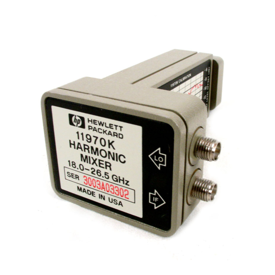
Page 11: 11970 Series Harmonic Mixers
General Information Introduction 11970 Series Harmonic Mixers Figure 1-1 Options Option 009, shown in Figure 1-2 on page 12, is a Mixer Connection Kit. It includes three low-loss SMA cables (Part Number 5061-5458), one hex-head balldriver (Part Number 8710-1539) for tightening the waveguide connector screws, and one 5/16-inch open-end wrench (Part Number 8710-0510) for use on the SMA connectors. - Page 12 • Agilent E4407B spectrum analyzers require option AYZ (LO Out and IF IN connections). • MMS analyzers using 11970 series mixers must have a front end model 70907A, 70907B, 70909A, or 70910A, as well as a 70900A/B with firmware new enough for those modules:...
-
Page 13: Specifications
Environmental Limitations The 11970 Series Mixers meet or exceed the environmental requirements of MIL-T-28800C, Type III, Class 3, Style C. Specific environmental qualifications for the mixers are as follows: Temperature, Non-operating: -40oC to 75oC Temperature, Operating: 0oC to 55oC Relative Humidity: 95 ±5% (up to 30oC) - Page 14 General Information Specifications Table 1-1 11970 Series Specifications Description Specifications Supplemental Information LO Amplitude Range 14 to 18 dBm Bias Requirements None Maximum CW RF Input Level 20 dBm (100 mW) Maximum Peak Pulse Power 24 dBm with <1μsec pulse...
- Page 15 General Information Specifications Table 1-2 11970K Specifications Description Specifications Supplemental Information RF Frequency Range 18 to 26.5 GHz The 11970K is not supported by the N9030A (PXA) LO Harmonic Number Odd Order Mixing Product >20 dB (nominal) Suppression LO Input Frequency Range 2.95 to 4.36 GHz Gain Compression Level (<1 dB) –3 dBm (nominal)
- Page 16 General Information Specifications Table 1-3 11970A Specifications Description Specifications Supplemental Information RF Frequency Range 26.5 to 40 GHz LO Harmonic Number Odd Order Mixing Product >20 dB (nominal) Suppression LO Input Frequency Range 3.27 to 4.96 GHz Gain Compression Level (<1 dB) –5 dBm (nominal) Maximum Conversion Loss 26 dB...
- Page 17 General Information Specifications Table 1-4 11970Q Specifications Description Specifications Supplemental Information RF Frequency Range 33 to 50 GHz LO Harmonic Number Odd Order Mixing Product >20 dB (nominal) Suppression LO Input Frequency Range 3.27 to 4.96 GHz Gain Compression Level (<1 dB) –7 dBm (nominal) Maximum Conversion Loss 28 dB...
- Page 18 General Information Specifications Table 1-5 11970U Specifications Description Specifications Supplemental Information RF Frequency Range 40 to 60 GHz LO Harmonic Number Odd Order Mixing Product >20 dB (nominal) Suppression LO Input Frequency Range 3.97 to 5.97 GHz Gain Compression Level (<1 dB) –7 dBm (nominal) Maximum Conversion Loss 28 dB...
- Page 19 General Information Specifications Table 1-6 11970V Specifications Description Specifications Supplemental Information RF Frequency Range 50 to 75 GHz LO Harmonic Number Odd Order Mixing Product >15 dB (nominal) Suppression LO Input Frequency Range 3.55 to 5.33 GHz Gain Compression Level (<1 dB) –3 dBm (nominal) Maximum Conversion Loss 40 dB...
- Page 20 General Information Specifications Table 1-7 11970W Specifications Description Specifications Supplemental Information RF Frequency Range 75 to 110 GHz LO Harmonic Number Odd Order Mixing Product >15 dB (nominal) Suppression LO Input Frequency Range 4.15 to 6.09 GHz Gain Compression Level (<1 dB) –1 dBm (nominal) Maximum Conversion Loss 46 dB...
- Page 21 General Information Specifications PHYSICAL CHARACTERISTICS Model Weight Flange 11970K UG-595/U 0.17 kg 36 mm 51 mm 90 mm WR-42 0.36 lb 1.4 in 2.0 in 3.5 in 11970A UG-599/U 0.14 kg 36 mm 51 mm 71 mm WR-28 0.32 lb 1.4 in 2.0 in 2.8 in...
- Page 22 General Information Specifications...
- Page 23 Operation...
-
Page 24: Introduction
Operation Introduction Introduction This section provides information on how to make effective use of the 11970 mixers. Operating Precautions Refer to the sections below for specific parameters to follow prior to mixer operation. Do not exceed the maximum ratings listed below or permanent damage to the WARNING mixer will result. -
Page 25: Getting Started
Operation Getting Started Getting Started The 11970 series of millimeter wave mixers have no bias or back-short adjustments. 11970 Mixers require an LO power of 14 to 18 dBm at the LO input. Mixer Connections This chapter contains connection and operation information listed by Spectrum Analyzer model number... -
Page 26: Using The Mixers With The E4407B Spectrum Analyzer (Option Ayz)
Using the Mixers with the E4407B Spectrum Analyzer (Option AYZ) The Agilent Technologies E4407B spectrum analyzer contains an extensive menu of functions that help with millimeter measurements. The following examples explain how to connect external mixers to the spectrum analyzer, choose the band of interest, store and activate conversion-loss factors, and how to use the signal-identification functions. - Page 27 Operation Using the Mixers with the E4407B Spectrum Analyzer (Option AYZ) Amplitude Calibration The conversion loss versus frequency data can be entered on your analyzer from one of three sources. • From a Conversion Loss Data Disk, supplied with your mixer. •...
- Page 28 Operation Using the Mixers with the E4407B Spectrum Analyzer (Option AYZ) Manually Entering Conversion-Loss Data 1. The analyzer frequency band will be set to . To choose a different band, press 26.5 – 40 GHz (A) Mix Band and then press the desired band frequency range/letter key. For this example, we will use band A, which ranges from 26.5 GHz to 40 GHz.
- Page 29 Operation Using the Mixers with the E4407B Spectrum Analyzer (Option AYZ) Figure 2-2 Identification of valid responses is achieved by simply turning on the signal-identification feature. (instrument preset selects the Image Suppress signal identification mode.) Press Input/Output Input Mixer Signal Ident (On) and note that now only the valid response (35 GHz) remains.
-
Page 30: Using The Mixers With The E4440A, E4446A, Or E4448A Psa Series Spectrum Analyzer (Option Ayz)
Using the Mixers with the E4440A, E4446A, or E4448A PSA Series Spectrum Analyzer (Option AYZ) The Agilent Technologies PSA Series spectrum analyzers contain an extensive menu of functions that help with millimeter measurements. Prior to starting this procedure, refer to “Spectrum Analyzer Retrofit... - Page 31 Operation Using the Mixers with the E4440A, E4446A, or E4448A PSA Series Spectrum Analyzer (Option AYZ) Amplitude Calibration The conversion loss versus frequency data can be entered on your analyzer from one of three sources. • From a Conversion Loss Data Disk, supplied with your mixer. See “Using a Conversion-Loss Data Disk”...
- Page 32 Operation Using the Mixers with the E4440A, E4446A, or E4448A PSA Series Spectrum Analyzer (Option AYZ) More correction points entered across the band in use will improve frequency NOTE response accuracy. Up to 200 points may be defined for each set. 4.
- Page 33 Operation Using the Mixers with the E4440A, E4446A, or E4448A PSA Series Spectrum Analyzer (Option AYZ) Figure 2-6...
-
Page 34: Using The 11970A, Q, U, V, And W Mixers With The X- Series Signal Analyzers (Option Exm)
Operation Using the 11970A, Q, U, V, and W Mixers with the X- Series Signal Analyzers (Option EXM) Using the 11970A, Q, U, V, and W Mixers with the X- Series Signal Analyzers (Option EXM) Refer to “Spectrum Analyzer Retrofit Requirements” on page 9 for configuration requirements. -
Page 35: Amplitude Calibration
Operation Using the 11970A, Q, U, V, and W Mixers with the X- Series Signal Analyzers (Option EXM) frequency or a start and stop frequency. 7. Many responses may appear on screen. Turn on the Signal ID function to identify true signals from images and harmonics. - Page 36 Operation Using the 11970A, Q, U, V, and W Mixers with the X- Series Signal Analyzers (Option EXM) Down loading the conversion loss .csv files to the analyzer corrections array 1. Install the CD ROM provided with the mixer, into a PC and view the contents of the CD. 2.
- Page 37 Operation Using the 11970A, Q, U, V, and W Mixers with the X- Series Signal Analyzers (Option EXM) Loading the .csv file automatically populates the Description and Comment fields found under the Corrections, Properties key. To edit these fields, press Input/ Output More Corrections...
-
Page 38: Signal Id
Operation Using the 11970A, Q, U, V, and W Mixers with the X- Series Signal Analyzers (Option EXM) Signal ID Image Suppress The Image Suppress mode of Signal ID mathematically removes all image and multiple responses of signals present at the mixer input. Two hidden sweeps are taken in succession. The second sweep is offset in LO frequency by 2*IF/N. -
Page 39: Using The Mixers With The 856X Series Spectrum Analyzers
Operation Using the Mixers with the 856X Series Spectrum Analyzers Using the Mixers with the 856X Series Spectrum Analyzers External millimeter mixers can be used to extend the frequency coverage of the 8560 E-Series and EC-Series spectrum analyzers. (The 8560E/EC Option 002 and Option 327 do not have external mixing capability.) The 8560 E-Series and EC-Series spectrum analyzers contain an extensive menu of functions that help with millimeter measurements. -
Page 40: Select The Frequency Band
Operation Using the Mixers with the 856X Series Spectrum Analyzers Select the Frequency Band 2. Specify unpreselected external mixing by pressing , then until UNPR CONFIG EXT MXR PRE UNPR is selected. 3. To select a frequency above 18 GHz: a. -
Page 41: Save The Average Conversion-Loss Value
4. Default conversion-loss values that are stored in the analyzer for each frequency band are listed in Table 2-1 on page 40. These values approximate the values for the Agilent 11970 series mixers. Other conversion-loss values may be entered into the spectrum analyzer in two ways. The first method lets... -
Page 42: Signal Identification
Operation Using the Mixers with the 856X Series Spectrum Analyzers Figure 2-10 Store and correct for conversion loss. The second method for storing conversion-loss information lets you save individual conversion-loss data points at specific intervals across the harmonic band, using CNV LOSS VS FREQ To view or enter a conversion-loss data point: a. -
Page 43: Identify Signals With The Frequency-Shift Method
Operation Using the Mixers with the 856X Series Spectrum Analyzers Figure 2-11 Signal Responses Produced by a 50 GHz Signal in U Band Identify signals with the frequency-shift method 6. Signal-identification routines that identify the signal and images are available on instruments with firmware revisions ≤920528, or with Option 008. - Page 44 Operation Using the Mixers with the 856X Series Spectrum Analyzers Figure 2-12 Response for Invalid Signals Figure 2-13 Response for Valid Signals...
-
Page 45: Identify Signals In Wide Frequency Spans
Operation Using the Mixers with the 856X Series Spectrum Analyzers Identify signals in wide frequency spans identifies signals in wide frequency spans, using harmonic search. SIG ID AT MKR SIG ID AT MKR automatically determines the proper frequency of a signal and displays its value on the spectrum analyzer. - Page 46 Operation Using the Mixers with the 856X Series Spectrum Analyzers Figure 2-15 SIG ID AT MKR Performed on a True Signal...
-
Page 47: Using The Mixers With Mms Analyzers
Operation Using the Mixers with MMS Analyzers Using the Mixers with MMS Analyzers Preliminary Operation This section provides information for the Agilent 70907A (or B), however the NOTE operation of the Agilent 70909A and Agilent 70910A is similar. Minor differences may be noted, but the necessary deviations from these exact instructions will be obvious. -
Page 48: Operation
Operation Using the Mixers with MMS Analyzers Operation Band Selection Use the following key sequence to enter the external mixing mode and to select the desired band of operation: MENU Select Input - choose external mixer input, for example: “IN 2 EM 70910A” State ext mixer fulband KAQUVE... - Page 49 Operation Using the Mixers with MMS Analyzers General Descriptions of Agilent 71000 Series Spectrum Analyzer External-Mixing Functions Allows access to the following softkey functions that control the measurement range ext mixer when an external mixer extends the spectrum analyzer frequency range. The mixer softkey can be found under the State...
- Page 50 Operation Using the Mixers with MMS Analyzers CONV LOSS (conversion loss) Offsets the reference level to compensate for amplitude losses at the active input port. If necessary, use select input to activate the desired input port before specifying its conversion-loss offset. To clear the offset, enter a conversion loss of zero.
- Page 51 Operation Using the Mixers with MMS Analyzers See the table below for available frequency ranges and related harmonic numbers. NOTE Use the softkeys for the image IMAGE N START IMAGE N STOP identification only. Table 2-3 Frequency Ranges and Corresponding Harmonic Numbers Band/Range Harmonic Number and Sign of IF (N) −1...
-
Page 52: Conversion Loss Versus Frequency Correction
The Agilent 71000 Series Spectrum Analyzers with the Agilent 70907A (or B) External Mixer Interface Module installed has the amplitude-correction function (AMPCOR) available by remote programming. Use AMPCOR to compensate for the Agilent 11970 Series frequency-dependent conversion-loss variations. Up to 200 pairs of frequency-amplitude correction points can be entered, depending on the amount of available internal memory. - Page 53 Operation Using the Mixers with MMS Analyzers To print out an existing AMPCOR table, use the program listed below: 10 dim A$ (1:20) [30] 20 OUTPUT 718; “CONVLOSS 0DB;” 30 OUTPUT 718; “AMPCOR 50 GHZ, 46.1DB, 52GHZ, 46.7DB, 53GHZ,47.2DB;” 40 ! 50 OUTPUT 718;...
-
Page 54: Using The Mixers With The 8566B Spectrum Analyzer
Operation Using the Mixers with the 8566B Spectrum Analyzer Using the Mixers with the 8566B Spectrum Analyzer Set up the equipment 1. Connect the external harmonic mixer to the spectrum analyzer, as shown in Figure 2-17. Good-quality shielded SMA-type cables should be used to connect the mixer to the NOTE spectrum analyzer to ensure that no signal attenuation occurs. -
Page 55: Amplitude Calibration
Amplitude Calibration Procedure Each 11970 series harmonic mixer is characterized at the factory and comes with a calibration chart (See Figure 2-20 on page 58). The horizontal axis of the chart gives the frequency range of the mixer and the two vertical axis scales are calibrated in conversion loss and in reference level offset. -
Page 56: Signal Identification
Operation Using the Mixers with the 8566B Spectrum Analyzer Signal Identification Figure 2-18 on page 55 shows a typical full-band display of a single input signal. Direct interpretation of the display is difficult because of the large number of responses produced by several local oscillator harmonics generated in the mixer. - Page 57 Operation Using the Mixers with the 8566B Spectrum Analyzer Figure 2-19...
- Page 58 Operation Using the Mixers with the 8566B Spectrum Analyzer Figure 2-20...
-
Page 59: Service
Service... -
Page 60: Maintenance
Maintenance Maintenance The only maintenance required for the 11970 Series Mixers is preventive maintenance. When you are not using your mixer, cover its waveguide input with its waveguide cap. Also, though the 11970 Mixers can absorb more punishment than is normal for such devices, you should avoid subjecting them to unnecessary shock or vibration. - Page 61 Service Maintenance Figure 3-1 11970 Series Mixer Schematic Diagram Model LPF Fco (GHz) 11970K 11970A 11970Q 11970U 11970V 11970W...
- Page 62 Service Maintenance Table 3-1 Accessories and Replaceable Parts Part Number Description 5061-5460: Mixer Connector Kit (Option 009), includes the following three items: 5061-5458 Cable, 1 meter long, SMA male connectors (3 required) 8710-0510 Wrench, 5/16-inch, open-end 8710-1539 Ball Driver, 3/32-inch 3030-0221 Socket Head Cap Screw, 4-40 thread, .375 inches long (flange connecting screw for 11970K and 11970A)
- Page 63 Service Maintenance Table 3-2 Locations for Agilent Technologies Online assistance: http://www.agilent.com/find/assist Americas Canada Latin America United States 1 877 894 4414 (305) 269 7500 1 800 829 4444 Asia Pacific Australia China Hong Kong 1 800 629 485 800 810 0189...