Sharp ER-A410 Service Manual
Hide thumbs
Also See for ER-A410:
- Instruction manual (190 pages) ,
- Programming manual (53 pages) ,
- Service manual (6 pages)
Advertisement
q
ER-A410
CHAPTER 1. SPECIFICATIONS . . . . . . . . . . . . . . . . . . . . . . . . . . . . 1
CHAPTER 2. OPTIONS . . . . . . . . . . . . . . . . . . . . . . . . . . . . . . . . . . . 5
CHAPTER 3. MASTER RESET AND PROGRAM RESET. . . . . . . . . 6
CHAPTER 4. HARDWARE DESCRIPTION . . . . . . . . . . . . . . . . . . . . 7
CHAPTER 5. DIAGNOSTIC PROGRAM . . . . . . . . . . . . . . . . . . . . . 15
CHAPTER 6. IPL FROM EP-ROM . . . . . . . . . . . . . . . . . . . . . . . . . . 20
CHAPTER 7. CIRCUIT DIAGRAM AND PWB LAYOUT . . . . . . . . . 21
PARTS GUIDE
Parts marked with "!" are important for maintaining the safety of the set. Be sure to replace these parts with specified
ones for maintaining the safety and performance of the set.
SERVICE MANUAL
ER-A4 0
CONTENTS
SHARP CORPORATION
CODE : 00Z
ELECTRONIC
CASH REGISTER
ER-A410
ER-A420
MODEL
SRV KEY : LKGIM7113RCZZ
PRINTER : PR-45M II
(V version)
ERA410VSME
This document has been published to be used
for after sales service only.
The contents are subject to change without notice.
Advertisement

Related Manuals for Sharp ER-A410


Summary of Contents for Sharp ER-A410
-
Page 1: Table Of Contents
SERVICE MANUAL CODE : 00Z ERA410VSME ELECTRONIC CASH REGISTER ER-A410 ER-A410 ER-A420 MODEL SRV KEY : LKGIM7113RCZZ PRINTER : PR-45M II (V version) ER-A4 0 CONTENTS CHAPTER 1. SPECIFICATIONS ......1 CHAPTER 2. - Page 2 IF THE MODE SW IS SET TO THE SRV' POSITION WHEN THE POWER IS OFF, THE MACHINE WILL NOT OPERATE PROPERLY EVEN T HOUGH THE POWER IS TURNED ON. DO NOT SET THE MODE SW TO THE SRV' POSITION WHEN THE POWER IS OFF. ER-A410/ER-A420...
-
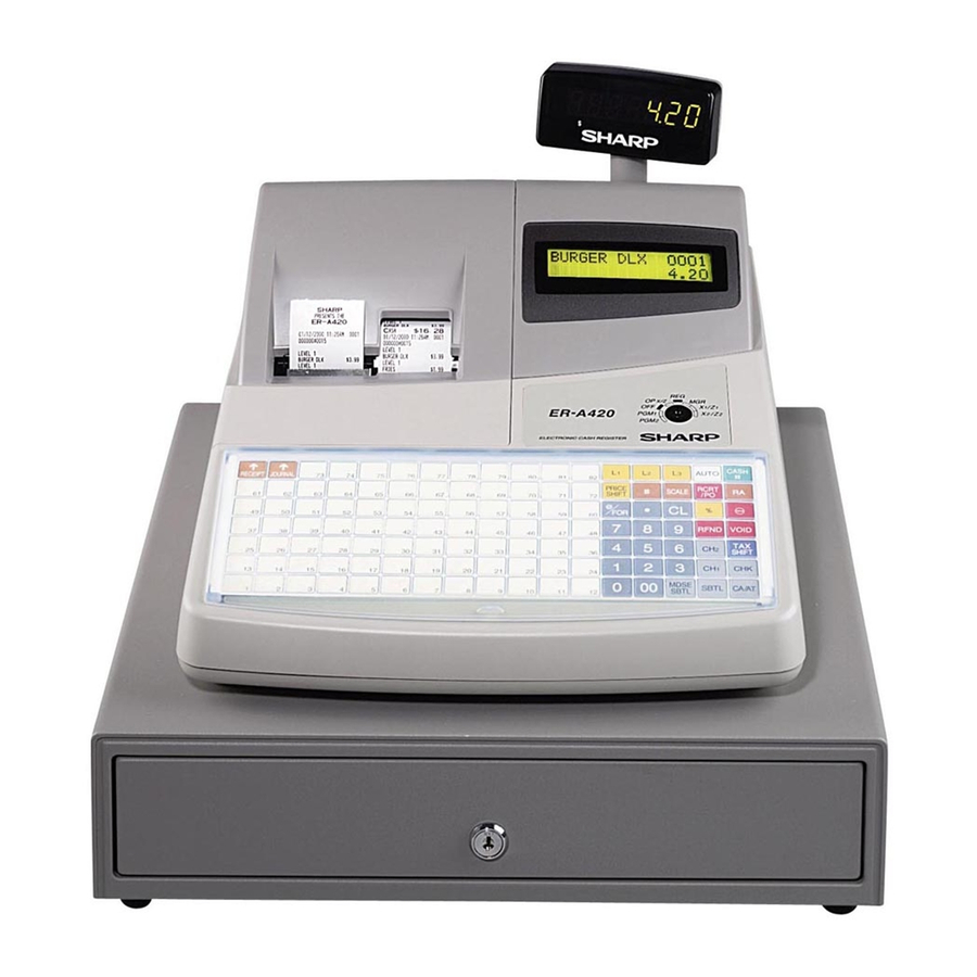
Page 3: Chapter 1. Specifications
CHAPTER 1. SPECIFICATIONS 1. APPEARANCE 3-2. KEY LAYOUT ER-A410 KEYLAYOUT ER-A410 p pap Note: All the keys but the receipt paper feed and journal paper feed keys can be re-positioned. If you want to change the layout, consult your dealer. - Page 4 Note: The department and direct PLU keys can be extended, if you Clear key require extension of the department or direct PLU keys, please contact your dealer. 1 ~ 6 Department keys PLU/SUB Price lookup/subdepartment key ER-A410/ER-A420 SPECIFICATIONS – 2 –...
- Page 5 -for example, after-transac- tion voiding and override entry. X1/Z1: To take the X/Z report for various daily totals X2/Z2: To take the X/Z report for various periodic (weekly or monthly) consolidation ER-A410/ER-A420 SPECIFICATIONS – 3 –...
- Page 6 • Method: Manual Error message When an error occurs, the corresponding error message is displayed in the function message display area. Customer display (Pop-up type) er sa e ar a ears er sa e ER-A410/ER-A420 SPECIFICATIONS – 4 –...
-
Page 7: Chapter 2. Options
2. SERVICE OPTIONS NAME PARTS CODE PRICE RANK REMARK LKGIM7113RCZZ SRV key GCOVH2541BHZB Water proof switch cover GCOVH2541BHZA Water proof keyboard cover For ER-A410 GCOVH2541BHSA Text preset key cover For ER-A410 PSHEK3008BHZZ Blank sheet For ER-A420 ER-A410/ER-A420 OPTIONS – 5 –... -
Page 8: Chapter 3. Master Reset And Program Reset
Note: Procedure B and C cannot reset the hardware. RECEIPT FEED key, turn the mode switch to (SRV) position from (SRV’) position. It must be operated “Procedure A” to reset the hardware. ER-A410/ER-A420 MASTER RESET AND PROGRAM RESET – 6 –... -
Page 9: Chapter 4. Hardware Description
80000h~FFFFFh 258KB (Moves to Bank 1 when rewriting using EPROM.) CGROM /CS0 area BANK 2,3 address 40000h~BFFFFh (512KB x 2) /CS3 area BANK0 address 04000h~07FFFh 16KB *CGROM is available only for the Japanese market. ER-A410/ER-A420 HARDWARE DESCRIPTION – 7 –... - Page 10 /CS0 Out L DATA/CE Out L LCD DATA 49 O /CS1 /CS1 Out H LATCH SIGNAL 48 O /CS2 /CS2 Out H BLON Out L BACK LIGHT ON 47 O /CS3 /CS3 Out L ER-A410/ER-A420 HARDWARE DESCRIPTION – 8 –...
- Page 11 No energizing should be allowed at least 30 ms after stopping the motor before restarting. When starting the motor, the first excitation phase is RUSH energized for 10 ms to start the motor by acceleration control. ER-A410/ER-A420 HARDWARE DESCRIPTION – 9 –...
- Page 12 4-2. HEAD CONTROL HEAD: 864 dots in all Printable range The following three kinds of signals are inputted to the A/D conversion RECEIPT side 384 dots port of the ER-A410/420. JOURNAL side 384 dots <CPU’s PORT> Related PORT Signal to...
- Page 13 The normal keyboard reads key data 10~100us before turning off the strobe signal of the keyboard. 50 5 DB0-7 Valid Data Max. 10 BLANK BLANK BLANK 4003h 4003h 400 h 4003h 4003h 10 100 001xxxxx 011xxxxx DATA 001xxxxx 001xxxxx ER-A410/ER-A420 HARDWARE DESCRIPTION – 11 –...
- Page 14 (Status register) When WRITE: Indicates the EFT I/F 6-4. DISPLAY status. When READ: EFT sub system reset The ER-A410/A420 is provided with the front LCD of 5 x 7dot, 2 lines 16 control digits, and the 7-digit LED on the pop up side. FRONT:...
- Page 15 CPU PORT Signal to be used 11. DRAWER /RTS0 /RS2 RXD0 The ER-A410/A420 is provided with 2CH of DRAWER ports. TXD0 The DRAWER solenoid energizing time is as shown below. /ER2 50ms (max) 45ms(min) <Serial I/O ch2 receive signal> Read...
- Page 16 Bit6 Bit5 Bit4 Bit3 Bit2 Bit1 Bit0 04003h <EFT Data> Write/Read Address Bit7 Bit6 Bit5 Bit4 Bit3 Bit2 Bit1 Bit0 0400Eh <EFT Status> Read Address Bit7 Bit6 Bit5 Bit4 Bit3 Bit2 Bit1 Bit0 0400Fh ER-A410/ER-A420 HARDWARE DESCRIPTION – 14 –...
-
Page 17: Chapter 5. Diagnostic Program
--- will be displayed. 4 End of testing You can exit the test mode by turning the mode switch to a position other than the PGM mode. The printer prints as follows: 1 0 1 ER-A410/ER-A420 DIAGNOSTIC PROGRAM – 15 –... - Page 18 This data to which hard codes have been added is converted into 3 Check that: a decimal number value, which will become the sum check data that will be entered when DIAG is started. “–“ blinks and the clock counts up. ER-A410/ER-A420 DIAGNOSTIC PROGRAM – 16 –...
- Page 19 16 blocks and each 16 characters is displayed on the dot dis- x = 1: Data error play. x = 2: Address error When an error occurs, the printer outputs the error message and the address where the error has occurred in the area *****. ER-A410/ER-A420 DIAGNOSTIC PROGRAM – 17 –...
- Page 20 DATA error follows: SD RD error DATA error/framing error When the test ends normally: ******** (Model name) ******** (Version) When the test ends E – – ~ – – abnormally: ******** (Model name) ******** (Version) ER-A410/ER-A420 DIAGNOSTIC PROGRAM – 18 –...
- Page 21 If normal, the sum check of the EFT ROM is performed and the write/read check of the RAM is performed. 000 007 023 018 002 003 020 004 006 005 024 008 009 010 026 043 011 8 9 4 0 CHECK SUM : ER-A410/ER-A420 DIAGNOSTIC PROGRAM – 19 –...
-
Page 22: Chapter 6. Ipl From Ep-Rom
4. Turn the mode key switch to SRV’ position, and insert AC plug in AC outlet. 5. Turn the mode key switch to SRV position. The IPL procedure is started. When the procedure is completed, the message of “Completed.” Is shown. ER-A410/ER-A420 IPL FROM EP-ROM – 20 –... -
Page 23: Chapter 7. Circuit Diagram And Pwb Layout
ER-A410/ER-A420 CIRCUIT DIAGRAM AND PWB LAYOUT – 21 –... - Page 24 ER-A410/ER-A420 CIRCUIT DIAGRAM AND PWB LAYOUT – 22 –...
- Page 25 ER-A410/ER-A420 CIRCUIT DIAGRAM AND PWB LAYOUT – 23 –...
- Page 26 ER-A410/ER-A420 CIRCUIT DIAGRAM AND PWB LAYOUT – 24 –...
- Page 27 ER-A410/ER-A420 CIRCUIT DIAGRAM AND PWB LAYOUT – 25 –...
- Page 28 ER-A410/ER-A420 CIRCUIT DIAGRAM AND PWB LAYOUT – 26 –...
- Page 29 ER-A410/ER-A420 CIRCUIT DIAGRAM AND PWB LAYOUT – 27 –...
- Page 30 ER-A410/ER-A420 CIRCUIT DIAGRAM AND PWB LAYOUT – 28 –...
- Page 31 ER-A410/ER-A420 CIRCUIT DIAGRAM AND PWB LAYOUT – 29 –...
- Page 32 PWB LAYOUT MAIN PWB ER-A410/ER-A420 CIRCUIT DIAGRAM AND PWB LAYOUT – 30 –...
- Page 33 © COPYRIGHT 2002 BY SHARP CORPORATION All rights reserved. Printed in Japan. No part of this publication may be reproduced, stored in a retrieval system, or transmitted. In any form or by any means, electronic, mechanical, photocopying, recording, or otherwise, without prior written permission of the publisher.