Table of Contents
Advertisement
Quick Links
Advertisement
Table of Contents

Related Manuals for Panasonic KX-TG2257BXS


Summary of Contents for Panasonic KX-TG2257BXS
- Page 1 ORDER NO. KM40206887C3 Telephone Equipment KX-TG2257BXS 2.4GHz Digital Cordless Answering System Silver Version (for Asia, Middle Near East and Other area) © 2002 Kyushu Matsushita Electric Co., Ltd. All rights reserved. Unauthorized copying distribution is a violation of law.
-
Page 2: Table Of Contents
KX-TG2257BXS CONTENTS Page Page 1 ABOUT LEAD FREE SOLDER (PbF: Pb free) 8 DISASSEMBLY INSTRUCTIONS 1.1. Suggested PbF Solder 9 ASSEMBLY INSTRUCTIONS 1.2. How to recognize that Pb Free solder is used (at KX- 9.1. Assembly the LCD to P.C. Board (Handset) - Page 3 KX-TG2257BXS 11.8. Frequency Table 19 CPU DATA (Handset) 12 DESCRIPTION 19.1. IC201 12.1. Frequency 20 EXPLANATION OF RF UNIT TERMINALS 12.2. Time Division Duplex (TDD) operation 20.1. IC101 12.3. Signal Flowchart in the Whole System 21 HOW TO REPLACE A FLAT PACKAGE IC 13 EXPLANATION OF BBIC (Base Band IC) DATA 21.1.
-
Page 4: About Lead Free Solder (Pbf: Pb Free)
KX-TG2257BXS 1 ABOUT LEAD FREE SOLDER (PbF: Pb free) Note: In the information below, Pb, the symbol for lead in the periodic table of elements, will refer to standard solder or solder that contains lead. We will use PbF when discussing the lead free solder used in our manufacturing process which is made from Tin, (Tn), Silver, (Ag), and Copper, (Cu). -
Page 5: How To Recognize That Pb Free Solder Is Used (At Kx-Tg2257Bxs)
KX-TG2257BXS 1.2. How to recognize that Pb Free solder is used (at KX-TG2257BXS) 1.2.1. Base Unit PCB PBF is stamped on the upper of DC jack to show that Pb free solder is used.(See the figure below.) Stamped PBF IC201... -
Page 6: Standard Battery Life
KX-TG2257BXS 2 STANDARD BATTERY LIFE 2.1. Battery Charge Place the handset on the base unit and charge for about 15 hours before initial use. • • The IN USE/CHARGE indicator lights and a beep sounds. 2.2. Battery Strength You can check the battery strength on the handset display. -
Page 7: Battery Information
KX-TG2257BXS 2.4. Battery information After your Panasonic battery is fully charged: 3 BATTERY REPLACEMENT... -
Page 8: Location Of Controls
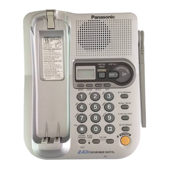
KX-TG2257BXS 4 LOCATION OF CONTROLS 4.1. Base unit... -
Page 9: Handset
KX-TG2257BXS 4.2. Handset... -
Page 10: Displays
KX-TG2257BXS 5 DISPLAYS Both the handset and the base unit show you instructions and information on the displays. These display prompts are shown below. 5.1. Handset display... - Page 11 KX-TG2257BXS...
-
Page 12: Base Unit Display
KX-TG2257BXS 5.2. Base unit display... -
Page 13: Connections
6 CONNECTIONS Note: • • USE ONLY WITH Panasonic AC ADAPTOR PQLV1BXZ. • • The AC adaptor must remain connected at all times. (It is normal for the adaptor to feel warm during use.) • • If your unit is connected to a PBX which does not support Caller ID services, you cannot access those services. -
Page 14: Adding Another Phone
KX-TG2257BXS 6.1. Adding Another Phone This unit will not function during a power failure. To connect a standard telephone on the same line, use a T-adaptor. -
Page 15: Operation
KX-TG2257BXS 7 OPERATION 7.1. Making Calls 7.1.1. Handset... - Page 16 KX-TG2257BXS...
- Page 17 KX-TG2257BXS...
- Page 18 KX-TG2257BXS...
- Page 19 KX-TG2257BXS 7.1.2. Base Unit (Digital Duplex Speakerphone)
- Page 20 KX-TG2257BXS...
-
Page 21: Answering Calls
KX-TG2257BXS 7.2. Answering Calls 7.2.1. Handset 7.2.2. Base Unit... -
Page 22: Automatic Answering Operation
KX-TG2257BXS 7.3. Automatic Answering Operation 7.3.1. Setting the Unit to Answer Calls... -
Page 23: Listening To Messages
KX-TG2257BXS 7.4. Listening to Messages 7.4.1. Slow Talk Message Playback... - Page 24 KX-TG2257BXS 7.4.2. During playback...
- Page 25 KX-TG2257BXS 7.4.3. From the Handset...
-
Page 26: Flash Button
KX-TG2257BXS 7.5. FLASH Button... -
Page 27: Disassembly Instructions
KX-TG2257BXS 8 DISASSEMBLY INSTRUCTIONS Shown in Fig.- To Remove Remove Lower Cabinet Screws (2.6 × 12)..(A) × 5 Main P.C. Board Remove the P.C. Board Antenna Screw (3 × 10)...(B ) × 1 Speaker Screws (3 × 8)...(C) × 3... - Page 28 KX-TG2257BXS Shown in Fig.- To Remove Remove Battery Cover Remove the Battery Cover Rear Cabinet Screws (2.6 × 12)..(D) × 2 Rear Cabinet Remove the Rear Cabinet Main P.C. Board Screw (2.6 × 12)..(E) × 1 Screws (2.6 × 10)..(F) × 2 Remove the lead wires Remove the P.C.
-
Page 29: Assembly Instructions
KX-TG2257BXS 9 ASSEMBLY INSTRUCTIONS 9.1. Assembly the LCD to P.C. Board (Handset) -
Page 30: Troubleshooting Guide
KX-TG2257BXS 10 TROUBLESHOOTING GUIDE Cross Reference: Check Power (P.31) (*1) See How to change the Auto Disconnect activation (time) (P.32) Error Message Table (P.31) Check Record (P.32) Check Playback (P.33) Check Sp-phone Transmission (P.34) Check Sp-phone Reception (P.34) Check Battery Charge (P.35) Check Link (P.35) -
Page 31: Check Power
KX-TG2257BXS 10.1. Check Power Cross Reference: Note: Power Supply Circuit (P.54) Flash Memory is IC300. Reset Circuit (P.55) DSP is IC201. 10.2. Error Message Table Note: Flash Memory is IC300. DSP is IC201. -
Page 32: Check Record
KX-TG2257BXS 10.3. Check Record How to change the Auto Disconnect activation (time) Some Telephone Company lines (fiber or cable) ON Hook and OFF Hook voltages are lower than conventional lines, which may cause a malfunction of Auto Disconnect detection.To solve this problem, try changing the Auto Disconnect activation (time) through the procedures below. -
Page 33: Check Playback
KX-TG2257BXS 10.4. Check Playback Cross Reference: Note: Power Supply Circuit (P.54) Flash Memory is IC300. DSP is IC201. -
Page 34: Check Sp-Phone Transmission
KX-TG2257BXS 10.5. Check Sp-phone Transmission Cross Reference: Note: Telephone Line Interface (P.56) Flash Memory is IC300. Signal Route (P.58) DSP is IC201. 10.6. Check Sp-phone Reception Cross Reference: Note: Telephone Line Interface (P.56) Flash Memory is IC300. Signal Route (P.58) -
Page 35: Check Battery Charge
KX-TG2257BXS 10.7. Check Battery Charge 10.8. Check Link Cross Reference: Check the RF Unit (P.36) Power Supply Circuit (P.54) Power Supply Circuit (P.62) Note: Base Unit Flash Memory is IC300. DSP is IC201. Handset EEPROM is IC202. DSP is IC201. -
Page 36: Check The Rf Unit
KX-TG2257BXS 10.9. Check the RF Unit 10.9.1. Defective Unit Check The defective unit should be checked using the HS of Regular unit (working) and BS of Regular unit (working). Both* of Regular unit (working) are required as the defect may be either in the handset or the base of the defective unit. For a defective BASE UNIT, place HS of Regular unit (working) on the cradle of the unit and check to see that the handset links with the base. - Page 37 KX-TG2257BXS b) BASE UNIT A short beep followed by a long beep is heard. This indicates the unit is in TEST POWER LOW mode. Once in TEST POWER LOW mode, to return the unit to the original NORMAL POWER mode, press 2, 5, 8, 0 simultaneously while the handset unit is in stand-by (not in use, not charging).
- Page 38 KX-TG2257BXS 10.9.3. RF Check Flowchart : Details of confirmation items are following in “Check Table for RF Block (P.39)”. Note: DSP is IC201. (for Base Unit) DSP is IC201. (for Handset) Both of RF Blocks for Handset and Base Unit are same.
- Page 39 KX-TG2257BXS 10.9.4. Check Table for RF Block Item BS (Base unit) (*1) HS (Handset) (*1) Link confirmation Procedure 1. Put “HS (working)” on BS. 1. Put HS on “BS (working)”. [NORMAL 2. Set MODE to [NORMAL POWER] of “HS 2. Set MODE to [NORMAL POWER] of “BS POWER] (working)“.
- Page 40 KX-TG2257BXS 10.9.5. RF-DSP interface signal wave form...
-
Page 41: Check Handset Transmission
KX-TG2257BXS 10.10. Check Handset Transmission Cross Reference: Signal Route (P.58). 10.11. Check Handset Reception Cross Reference: Signal Route (P.58). Note: When checking the RF UNIT, Refer to Check the RF Unit (P.36) 10.12. Check Caller ID Cross Reference: Telephone Line Interface (P.56). -
Page 42: Test Mode
KX-TG2257BXS 11 TEST MODE 11.1. Test mode flow chart for Base Unit (*1) It shows whether the telephone line is connected or not. -ON: OFF HOOK. -OFF: ON HOOK... -
Page 43: Tam Test Mode Flow Chart
KX-TG2257BXS 11.2. TAM Test mode flow chart... -
Page 44: Test Mode Flow Chart For Handset
KX-TG2257BXS 11.3. Test mode flow chart for Handset (*1) See Handset Reference Drawing (P.47).---Should return to OPEN after entering the Test mode. (*2) See Adjustment Battery Low Detector Voltage (P.45). 11.4. X201 Check The confirmation is made under the “TX Power Check” mode of TEST MODE. -
Page 45: Adjustment Battery Low Detector Voltage
KX-TG2257BXS 11.5. Adjustment Battery Low Detector Voltage After replacing handset’s DSP (IC201), Re-writing Battery Low voltage to EEPROM is required. <How to re-write> 1. Set 3.9V for DC power supply. 2. Enter the test mode (Refer to Test mode flow chart for Handset (P.44)) 3. -
Page 46: Base Unit Reference Drawing
11.6. Base Unit Reference Drawing When connecting the Simulator and Equipments for checking, please refer to below. for DC Power Supply FREQUENCY COUNTER (*2) DTMF TP_OSC SIMULATOR LED204 C412 C420 C421 AF OSC (1) R114 D107 R108 LED202 OSCILLOSCOPE D203 D106 AF VOLT METER R400... -
Page 47: Handset Reference Drawing
11.7. Handset Reference Drawing When connecting the Simulator and Equipments for checking, please refer to below. HEADSET AC VOLT METER HANDSET OPEN AC VOLT METER FREQUENCY OSCILLOSCOPE COUNTER (*2) 1.1kHz OSCILLOSCOPE SPECTRUM ANALYZER MIC1 Test IC203 MIC_H IC204 ANTG 1.1kHz IC201 MIC_P MIC LOAD... -
Page 48: Frequency Table
KX-TG2257BXS 11.8. Frequency Table Channel TX/RX Frequency (MHz) Channel TX/RX Frequency (MHz) 2472.70400 2415.36100 2473.21425 2415.87125 2474.75150 2417.40850 2475.26175 2417.91875 2475.77525 2418.43225 2476.28550 2418.94250 2476.80225 2429.18325 2477.31250 2429.69675 2477.82600 2430.20700 2478.33625 2430.72050 2478.84975 2431.23075 2479.36000 2431.74425 2479.87350 2432.25450 2411.77625 2433.79175 2412.28975... -
Page 49: Description
KX-TG2257BXS 12 DESCRIPTION 12.1. Frequency The frequency range of 2411.77625 MHz ~ 2479.87350 MHz is used. Transmitting and receiving channel between base unit and handset is same frequency. Refer to the Frequency Table. 12.2. Time Division Duplex (TDD) operation Transmission/reception between the base unit and handset is performed by time-sharing as shown in Fig. 7. 1 slot time of transmission and reception is 1mS. -
Page 50: Signal Flowchart In The Whole System
KX-TG2257BXS 12.3. Signal Flowchart in the Whole System Reception CN1 of the base unit is connected to the TEL line, and the signal is input through the bridge diode D4. While talking the relay (Q4) is turned ON and amplified at the amplifiers Q50, then led to DSP (IC201). DSP generates ADPCM signal. The ADPCM signal is input to RFIC (IC101) of RF UNIT. -
Page 51: Explanation Of Bbic (Base Band Ic) Data
KX-TG2257BXS 13 EXPLANATION OF BBIC (Base Band IC) DATA COMMUNICATION 13.1. Calling 13.3. Ringing 13.4. Ports for Transmitting and Receiving of Data 13.2. To Terminate Communication... -
Page 52: Block Diagram (Base Unit)
KIN5 KIN6 VMOD LCD CON RSTH IC331 PCTRL IC201 DTMF DATA IC332, Q102 Q108 IC100 3.6V 7.5V RXEN Analog TXEN Q104 RX GAIN 3.2V SHCTRL IC101 Q105 RSSI 3.3V 7.5V RXDATA (RXI) Q151 IC300 Q150 KX-TG2257BXS BLOCK DIAGRAM (BASE UNIT) -
Page 53: Circuit Operation (Base Unit)
KX-TG2257BXS 15 CIRCUIT OPERATION (Base Unit) General Description: (DSP, Flash Memory) is a digital speakerphone/speech/signal processing system that implements all the functions of speech compression, record and playback, and memory management required in a digital telephone answering machine. The DSP system is fully controlled by a host processor DSP. The host processor provides activation and control of all that functions as follows. -
Page 54: Power Supply Circuit
KX-TG2257BXS 15.3. Power Supply Circuit Function: The power supply voltage from AC adaptor is converted to the desired voltage of each block. Circuit Operation: This unit supplies the voltage to each block as shown below. 15.3.1. Charge Circuit The voltage from the AC is supplied to the main charge circuits. Normal charge (90 mA) of maximum 20-hours is started soon after the Handset is placed on the base unit. -
Page 55: Reset Circuit
KX-TG2257BXS 15.4. Reset Circuit Function: This circuit is used for to initialize the microcomputer when it incorporates an AC adaptor. Circuit Operation: When the AC Adaptor is inserted into the unit, then the voltage is shifted by IC100, D101 and power is supplied to the DSP. -
Page 56: Locator/Intercom Mode
KX-TG2257BXS 15.5. Locator/Intercom Mode 1. When the base unit LOCATOR/INTERCOM button is pressed, a call monitor signal (intercom sound) is output from DSP (SPP, SPN). Thus a monitor tone is heard from the speaker. 2. At the same time, flashing of the IN USE/CHARGE (LED201) is obtained from DSP (INUSE-LED). This status is called "Intercom stand-by". -
Page 57: Auto Disconnect Circuit
KX-TG2257BXS 15.7. Auto Disconnect Circuit Function: This circuit is used to detect the fact that another telephone connected to the same line is OFF-HOOK while the unit is in a receiving status or OGM transmitting status. Circuit Operation: The voltage DSP (DCIN) is monitored. If a parallel-connected telephone is put into an OFF HOOK status, the presence/absence of a parallel connection is determined when the voltage changes by 0.2V or more. -
Page 58: Signal Route
KX-TG2257BXS 15.9. Signal Route Each signal route is as follows. -
Page 59: Calling Line Identification (Caller Id)/Call Waiting Caller Id
KX-TG2257BXS 15.10. Calling Line Identification (Caller ID)/Call Waiting Caller ID Function: Caller ID The caller ID is a chargeable ID which the user of a telephone circuit obtains by entering a contract with the telephone company to utilize a caller ID service. For this reason, the operation of this circuit assumes that a caller ID service contract has been entered for the circuit being used. - Page 60 KX-TG2257BXS Call Waiting Caller ID Calling Identity Delivery on Call Waiting (CIDCW) is a CLASS service that allows a customer, while off-hook on an existing call, to receive information about a calling party on a waited call. The transmission of the calling information takes place almost immediately after the customer is alerted to the new call so he/she can use this information to decide whether to take the new call.
-
Page 61: Block Diagram (Handset)
CHARGE RXEN SPOUTP, SPOUTN RXI (RXDATA) 46 47 MIP, MIN RX GAIN LOUTO SIO_DO RINGER HSMIP SIO_LE HSSPOUT SIO_CLK LINO 16~22 27 LCD_∗ SPEAKER CN203 HEAD SET JACK TO LCD UNIT IC202 EEPROM (CALLER ID) LEDS KX-TG2257BXS BLOCK DIAGRAM (HANDSET) -
Page 62: Circuit Operation (Handset)
KX-TG2257BXS 17 CIRCUIT OPERATION (Handset) 17.1. Construction The circuit mainly consists of DSP and RF unit as shown in the block diagram. 17.1.1. DSP:IC201 Function • • Battery Low, Power down detect circuit • • Ringer Generation • • Interface circuit RF unit, speaker, mic, LED, Key scan, LCD, Headset 17.1.2. -
Page 63: Charge Circuit
KX-TG2257BXS 17.3. Charge Circuit Ni-Cd battery is connected to (BATT+, BATT-). When the handset is put on the cradle of the base unit, the power is supplied from CHARGE1 and CHARGE2 terminals to charge the battery. Q207 detects the voltage of CHARGE1 and CHARGE2 terminals, then the handset makes ID code setting (*) with the base unit. -
Page 64: Reception Signal
KX-TG2257BXS 17.6. Reception Signal The voice signal from the base unit is output to DSP (33) (HSSOUT). This signal is led to the headset jack (CN203) and DSP (44) (HSMIP). The signal input to DSP (44) is inverted and output to DSP (34) (LOUTO).The signal through the headset jack is inverted, then output from DSP (34) to drive the speaker. -
Page 65: Cpu Data (Base Unit)
KX-TG2257BXS 18 CPU DATA (Base Unit) 18.1. IC201... -
Page 66: Cpu Data (Handset)
KX-TG2257BXS 19 CPU DATA (Handset) 19.1. IC201... -
Page 67: Explanation Of Rf Unit Terminals
KX-TG2257BXS 20 EXPLANATION OF RF UNIT TERMINALS 20.1. IC101... -
Page 68: How To Replace Aflat Package Ic
KX-TG2257BXS 21 HOW TO REPLACE A 21.3. Removing Solder from Between Pins FLAT PACKAGE IC 1. Add a small amount of solder to the bridged pins. 21.1. Preparation 2. With a hot iron, use a sweeping motion along the flat part of the pin to draw the solder from between the adjacent pads. -
Page 69: Cabinet And Electrical Parts (Base Unit)
KX-TG2257BXS 22 CABINET AND ELECTRICAL PARTS (Base Unit) -
Page 70: Cabinet And Electrical Parts (Handset)
KX-TG2257BXS 23 CABINET AND ELECTRICAL PARTS (Handset) -
Page 71: Accessories And Packing Materials
KX-TG2257BXS 24 ACCESSORIES AND PACKING MATERIALS... -
Page 72: Terminal Guide Of The Ics, Transistors And Diodes
KX-TG2257BXS 25 TERMINAL GUIDE OF THE ICs, TRANSISTORS AND DIODES 25.1. Base Unit 25.2. Handset... -
Page 73: Replacement Parts List
KX-TG2257BXS 26 REPLACEMENT PARTS Ref. Part No. Part Name & Description Remarks PQGP10206Z1 PANEL, LCD AS-HB LIST L5DCBCB00009 LIQUID CRYSTAL DISPLAY PQHR10911Z SPACER, LCD HOLDER PS-HB Note: PQHR10914Z SPACER, LED GUIDE ABS-HB PQHS10327Z COVER, LCD TAPE 1. RTL (Retention Time Limited) - Page 74 KX-TG2257BXS Ref. Part No. Part Name & Description Remarks Ref. Part No. Part Name & Description Remarks PQLQXF3R3K COIL R204 ERJ3GEYJ271 L150 PQLQZK3R3K COIL R205 ERJ3GEYJ391 L151 PQLQZM100K COIL R206 ERJ3GEYJ821 L200 PQLQR2KA213 COIL R207 ERJ3GEYJ181 (CONNECTORS) R212 ERJ3GEYJ102 PQJJ2H003Z...
-
Page 75: Handset
KX-TG2257BXS Ref. Part No. Part Name & Description Remarks Ref. Part No. Part Name & Description Remarks C108 EEE0JA101SP C421 ECUV1H101JCV 100p C109 ECUV1H103KBV 0.01 C422 ECUV1H101JCV 100p C110 ECUV1C104ZFV C430 ECUV1H471JCV 470p C112 EEE1AA101SP C450 ECEA0JKA101 C114 ECEA1CK101 C453... - Page 76 KX-TG2257BXS Ref. Part No. Part Name & Description Remarks Ref. Part No. Part Name & Description Remarks Q211 PQVTDTA143TU TRANSISTOR(SI) R280 ERJ3GEYJ182 1.8k (DIODES) R281 ERJ3GEYJ104 100k D201 MA2ZD1400 DIODE(SI) R302 ERJ3GEYJ180 D203 MA111 DIODE(SI) R303 ERJ3GEYJ180 D206 PQVDMD5S DIODE(SI)
- Page 77 KX-TG2257BXS Ref. Part No. Part Name & Description Remarks C315 ECUV1H030CCV C316 ECUV1H221JCV 220p C317 ECUV1H010CCV L201 ECUV1H010CCV (OTHERS) E101 L0CBAB000044 MICROPHONE RA201 EXRV8V104JV RESISTOR ARRAY X201 H0J819400004 CRYSTAL OSCILLATOR 26.2.3. ACCESSORIES AND PACKING MATERIALS Ref. Part No. Part Name & Description...
-
Page 78: For Schematic Diagram
KX-TG2257BXS 27 FOR SCHEMATIC DIAGRAM 27.1. Base Unit (SCHEMATIC DIAGRAM (Base Unit)) Note: 1. DC voltage measurements are taken with voltmeter from the negative voltage line. 2. This schematic diagram may be modified at any time with the development of new technology. -
Page 79: Memo
KX-TG2257BXS 27.3. Memo... -
Page 80: Schematic Diagram (Base Unit)
KX-TG2257BXS 28 SCHEMATIC DIAGRAM (Base Unit) IC101 IC202 IC300 IC201... - Page 81 140mVp-p (-25dBm/600 Output Auto Disconnect Circuit Call ID data IC332 Reset Circuit IC331 7.5V 3.6V 3.3V IC100 -51dBm/600 1.1kHz 3.2V 9V DC. for H/S Charge Circuit SP Phone TX TALK TX SP PhoneRX TALK RX KX-TG2257BXS SCHEMATIC DIAGRAM (Base Unit)
-
Page 82: Schematic Diagram (Handset)
KX-TG2257BXS 29 SCHEMATIC DIAGRAM (Handset) IC202... - Page 83 KX-TG2257BXS Input 1.1kHz 18mVp-p (-45dBm/600 ) (Headset) (Headset) Input 1.1kHz -43dBm/600 IC201 IC205 3.3V IC203 3.3V IC204 KX-TG2257BXS SCHEMATIC DIAGRAM (Handset)
-
Page 84: Schematic Diagram (Rf Unit)
* When either Vpow or Vpow2 is in use, the other is out of use. Vpow * (for Base Unit) Vpow2 * (for Handset) SYN_DATA SYN_EN SYN_CLK TXMOD RXGAIN RXEN IC101 TXEN SHCTRL RX_DATA RSTN RSSI DEMOD (out of use) KX-TG2257BXS SCHEMATIC DIAGRAM (RF Unit) -
Page 85: Circuit Board (Rf Unit)
KX-TG2257BXS 31 CIRCUIT BOARD (RF Unit) 15 14 Vpow2 ANT 1 SYN_CLK SYN_DATA SYN_EN IC101 TXEN GND 18 RXEN SHCTRL KX-TG2257BXS CIRCUIT BOARD (RF Unit) -
Page 86: Memo
KX-TG2257BXS 31.1. MEMO... -
Page 87: Circuit Board (Base Unit)
Vcc (3.2V) D LINO Bell CHARGE_CTL IC101 IC202 IC201 IC332 IC300 IC100 IC331 G G G 3 4 5 HS MIP X'tal CLK Vcc (3.3V) B Reset: RST CHARGE_DET Power_DOWN: PDN Mic input KX-TG2257BXS CIRCUIT BOARD (Component View (Base UNIT)) -
Page 88: Flow Solder Side View
D150 R154 R156 R152 LED205 R153 D152 R155 R204 D109 J201 D108 LED201 J202 R100 D110 C121 C401 C723 D104 R400 D106 D203 LED202 R108 D107 R114 C421 C420 C412 LED204 KX-TG2257BXS CIRCUIT BOARD (Flow Solder Side View (Base Unit)) -
Page 89: Circuit Board (Handset)
KX-TG2257BXS 33 CIRCUIT BOARD (Handset) 33.1. Component View Reset: RST Power Down: PDN MIC1 17 16 15 14 IC203 MIC_H IC204 IC201 MIC_H IC202 VRF (3.3V) Test DSP VDD BATT Low KX-TG2257BXS CIRCUIT BOARD (Component View (Handset)) -
Page 90: Flow Solder Side View
KX-TG2257BXS 33.2. Flow Solder Side View LED210 LED205 R216 C211 R217 R206 C210 LED206 C209 C208 C207 R215 C206 LED209 R311 R312 R214 LED207 R314 R313 LED208 KX-TG2257BXS CIRCUIT BOARD (Flow Solder Side View (Handset)) - Page 91 KX-TG2257BXS KXTG2257BXS...