Table of Contents
Advertisement
Quick Links
Advertisement
Table of Contents

Related Manuals for KTI Networks KGS-2416


Summary of Contents for KTI Networks KGS-2416
- Page 1 ’ ’ DOC.090920...
- Page 3 User's Manual 16-Port SFP + 8-Port Combo GbE L2 Plus Managed Switch MANUFACTURE SOFTWARE LICENSE AGREEMENT NOTICE: Please carefully read this Software License Agreement (hereinafter referred to as this “Agreement”) before copying or using the accompanying software or installing the hardware unit with pre-enabled software or firmware (each of which is referred to as “Software” in this Agreement). BY COPYING OR USING THE SOFTWARE, YOU ACCEPT ALL OF THE PROVISIONS AND CONDITIONS OF THIS AGREEMENT.
-
Page 5: Table Of Contents
2-1-3-1. Cabling Requirements for TP Ports ... 15 2-1-3-2. Cabling Requirements for 1000SX/LX SFP Module... 15 2-1-3-3. Switch Cascading in Topology ... 17 2-1-4. Configuring the Management Agent of SW24GF ...20 2-1-4-1. Configuring the Management Agent of SW24GF through the Serial RS-232 Port ... 21 2-1-4-2. - Page 6 3-4-2. Static Filter ...75 3-4-3. Static Forward ...76 3-4-4. MAC Alias...77 3-4-5. MAC Table ...78 3-5. GVRP...79 3-5-1. Config ...79 3-5-2. Counter ...82 3-5-3. Group ...84 3-6. Q UALITY OF ERVICE 3-6-1. Ports...85 3-6-2. Qos Control List...87 3-6-3.Rate Limiters...93 3-6-4.Storm Control...95 3-6-5.Wizard ...96 3-7.
- Page 7 3-17-2. DHCP Snooping Entry...201 3-17-3. DHCP Snooping Client...202 3-18. LLDP...202 3-18-1 . LLDP State...203 3-18-2 . LLDP Entry...205 3-18-3 . LLDP Statistics ...207 3-19. S ...209 ESTORE 3-19-1. Factory Defaults ...210 3-19-2 . Save Start ...210 3-19-3 . Save User ...210 3-19-4 .
-
Page 8: Caution
If you need using outdoor device connect to this device with cable then you need to addition an arrester on the cable between outdoor device and this device. Fig. Addition an arrester between outdoor device and this switch Electronic Emission Notices... - Page 9 In this user’s manual, it will not only tell you how to install and connect your network system but configure and monitor the SW24GF through the built-in CLI and web by RS-232 serial interface and Ethernet ports step-by-step. Many explanations in detail of hardware and software functions are shown as well as the examples of the operation for web-based interface and command-line interface (CLI).
-
Page 10: Introduction
In this switch, Port 1 and Port 8 include two types of media --- TP and SFP Fiber (LC, BiDi LC…); this port supports 10/100/1000Mbps TP or 1000Mbps SFP Fiber with auto-detected function. - Page 11 IP multicast packets are running over the network. IGMP Proxy: The implementation of IP multicast processing. The switch supports IGMP version 1 and IGMP version 2, efficient use of network bandwidth, and fast response time for channel changing.
- Page 12 MAC address. Binding these two address types together allows the transmission of data between the layers. The primary purpose of IP- MAC binding is to restrict the access to a switch to a number of authorized users. Only the authorized client can access the Switch’s port by checking the pair of IP-MAC Addresses and port number with the pre-configured database.
-
Page 13: Checklist
1-2. Checklist Before you start installing the switch, verify that the package contains the following: ⎯ SW24GF 24-port Layer 2 plus Gigabit Managed Switch ⎯ SFP Modules (optional) ⎯ Mounting Accessory (for 19” Rack Shelf) ⎯ This User's Manual in CD-ROM ⎯... - Page 14 • The trap event and alarm message can be transferred via e-mail • Supports diagnostics to let administrator knowing the hardware status • Supports loop detection to protect the switch crash when the networking has looping issue • HTTP and TFTP for firmware upgrade, system log upload and configuration file import/export •...
-
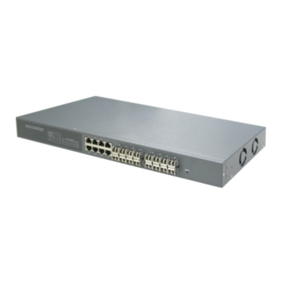
Page 15: View Of Sw24Gf
LED display area, locating on the left side of the panel, contains a Power LED, which indicates the power status and 24 ports working status of the switch. One RS-232 DB-9 interface is offered for configuration or management. -
Page 16: Ac Power Input On The Rear Panel
Fig. 1-3 Rear View of SW24GF 1-5. View of the Optional Modules In the switch, Port 1~ 8 includes two types of media --- TP and SFP Fiber (LC, BiDi LC…); this port supports 10/100/1000Mbps TP or 1000Mbps SFP Fiber with auto-detected function. -
Page 17: Installation
At the beginning, please do first: ⇒ Wear a grounding device to avoid the damage from electrostatic discharge ⇒ Be sure that power switch is OFF before you insert the power cord to power source • Installing Optional SFP Fiber Transceivers to the SW24GF Note: If you have no modules, please skip this section. - Page 18 ⇒ Use Cat. 5 grade RJ-45 TP cable to connect to a TP port of the switch and the other end is connected to a network-aware device such as a workstation or a server.
-
Page 19: Installing Chassis To A 19-Inch Wiring Closet Rail
⇒ Wear a grounding device for electrostatic discharge. ⇒ Screw the mounting accessory to the front side of the switch (See Fig. 2-2). ⇒ Place the Chassis into the 19-inch wiring closet rail and locate it at the proper position. Then, fix the Chassis by screwing it. - Page 20 ⎯ Gigabit Fiber with BiDi LC 1310nm SFP module ⎯ Gigabit Fiber with BiDi LC 1550nm SFP module The following table lists the types of fiber that we support and those else not listed here are available upon request. Multi-mode 62.5/125μm IEEE 802.3z Modal Gigabit Ethernet...
-
Page 21: Switch Cascading In Topology
If more than two switches are connected in the same network, select one switch as Level 1 switch and connect all other switches to it at Level 2. Server/Host is recommended to connect to the Level 1 switch. - Page 22 Case1: All switch ports are in the same local area network. Every port can access each other (See Fig. 2-3). Fig. 2-3 No VLAN Configuration Diagram If VLAN is enabled and configured, each node in the network that can communicate each other directly is bounded in the same VLAN area.
- Page 23 Case 2b: Port-based VLAN (See Fig.2-5). 1. VLAN1 members could not access VLAN2, VLAN3 and VLAN4 members. 2. VLAN2 members could not access VLAN1 and VLAN3 members, but they could access VLAN4 members. VLAN3 members could not access VLAN1, VLAN2 and VLAN4. 4.
-
Page 24: Configuring The Management Agent Of Sw24Gf
2-1-4. Configuring the Management Agent of SW24GF We offer you three ways to startup the switch management function. They are RS-232 console, CLI, and Web. Users can use any one of them to monitor and configure the switch. You can touch them through the following procedures. -
Page 25: Configuring The Management Agent Of Sw24Gf Through The Serial Rs-232 Port
RS-232 cable with DB-9 connector. Next, run a terminal emulator with the default setting of the switch’s serial port. With this, you can communicate with the switch. In the switch, RS-232 interface only supports baud rate 115200 bps with 8 data bits, 1 stop bit, no parity check and no flow control. - Page 26 Please refer to Fig. 2-7 CLI Management for details about ex-factory IP setting. They are default setting of IP address. You can first either configure your PC IP address or change IP address of the switch, next to change the IP address of default gateway and subnet mask.
-
Page 27: Configuring The Management Agent Of Sw24Gf Through The Ethernet Port
IP address or to know the IP address of the switch. Then, follow the procedures listed below. 1. Set up a physical path between the configured the switch and a PC by a qualified UTP Cat. 5 cable with RJ-45 connector. -
Page 28: Ip Address Assignment
2-1-5. IP Address Assignment For IP address configuration, there are three parameters needed to be filled in. They are IP address, Subnet Mask, Default Gateway and DNS. IP address: The address of the network device in the network is used for internetworking communication. - Page 29 Network address Class B: IP address range between 128.0.0.0 and 191.255.255.255. Each class B network has a 16-bit network prefix followed 16-bit host address. There are 16,384 (2^14)/16 networks able to be defined with a maximum of 65534 (2^16 –2) hosts per network.
- Page 30 subnet is used to determine how to split an IP address to the network prefix and the host address in bitwise basis. It is designed to utilize IP address more efficiently and ease to manage IP network. For a class B network, 128.1.2.3, it may have a subnet mask 255.255.0.0 in default, in which the first two bytes is with all 1s.
- Page 31 Basically, it is a routing policy. The gateway setting is used for Trap Events Host only in the switch. For assigning an IP address to the switch, you just have to check what the IP address of the network will be connected with the switch. Use the same network address and append your host address to it.
- Page 32 IP address. To connect to a server, the client needs to know the IP of the server. However, user generally uses the name to connect to the server. Thus, the switch DNS client program (such as a browser) will ask the DNS to resolve the IP address of the named server.
-
Page 33: Typical Applications
LC and BiDi-LC SFP modules. For more details on the specification of the switch, please refer to Appendix A. The switch is suitable for the following applications. - Page 34 Fig. 2-14 Peer-to-peer Network Connection Fig. 2-15 Office Network Connection...
-
Page 35: Operation Of Web-Based Management
Gigabit SFP and 8-Port Gigabit TP/SFP Fiber management Ethernet switch. With this facility, you can easily access and monitor through any one port of the switch all the status of the switch, including MIBs status, each port activity, Spanning tree status, port aggregation status, multicast traffic, VLAN and priority status, even illegal access record and so on. -
Page 36: Web Management Home Overview
3-1. Web Management Home Overview After you login, the switch shows you the system information as Fig. 3-2. This page is default and tells you the basic information of the system, including “Model Name”, “System Description”, “Location”, “Contact”, “Device Name”, “System Up... - Page 37 The Information of Page Layout ⎯ On the top side, it shows the front panel of the switch. In the front panel, the linked ports will display green; as to the ports, which are link off, they will be dark. For the optional modules, the slot will show only a cover plate if no module exists and will show a module if a module is present.
- Page 38 Root System VLAN GVRP SNMP IP MAC Binding Trunk MSTP Multicast DHCP Snooping Save/Restore Diagnostics Logout Port 802.1X Mirroring Alarm LLDP Export/Imports Maintenance...
-
Page 39: System Information
Parameter description: Model name: The model name of this device. System description: As it is, this tells what this device is. Here, it is “L2 Plus Managed Switch”. Location: Basically, it is the location where this switch is put. User-defined. Contact: For easily managing and maintaining device, you may write down the contact person and phone here for getting help soon. - Page 40 The time accumulated since this switch is powered up. Its format is day, hour, minute, second. Current time: Show the system time of the switch. Its format: day of week, month, day, hours: minutes: seconds, year. For instance, Mon, March. 03, 14:54:07, 2008.
-
Page 41: Account Configuration
“Minute” and “Second” within the valid value range indicated in each item. If you input an invalid value, for example, 61 in minute, the switch will clamp the figure to NTP is a well-known protocol used to synchronize the clock of the switch system time over a network. - Page 42 Greenwich Mean Time (GMT). If use the NTP mode and select a built-in NTP time server or manually specify an user-defined NTP server as well as Time Zone, the switch will sync the time in a short after pressing <Apply> button. Though it synchronizes the time automatically, NTP does not update the time periodically without user’s processing.
- Page 43 The switch supports valid configurable day light saving time is –5 ~ +5 step one hour. The zero for this parameter means it need not have to adjust current time, equivalent to in-act daylight saving.
-
Page 44: Ip Configuration
The switch supports both manual IP address setting and automatic IP address setting via DHCP server. When IP address is changed, you must reboot the switch to have the setting taken effect and use the new IP to browse for web management and CLI management. - Page 45 IP address: Users can configure the IP settings and fill in new values if users set the DHCP function “Disable”. Then, click <Apply> button to update. When DHCP is disabled, Default: 192.168.1.1 If DHCP is enabled, this field is filled by DHCP server and will not allow user manually set it any more.
- Page 46 The switch supports DNS client function to re-route the mnemonic name address to DNS server to get its associated IP address for accessing Internet. User can specify a DNS IP address for the switch. With this, the switch can translate a mnemonic name address into an IP address.
-
Page 47: Loop Detection
3-1-5. Loop Detection The loop detection is used to detect the presence of traffic. When switch receives packet’s(looping detection frame) MAC address the same as oneself from port, show Loop detection happens. The port will be locked when it received the looping detection frames. -
Page 48: Management Policy
3-1-6. Management Policy Through the management security configuration, the manager can do the strict setup to control the switch and limit the user to access this switch. The following rules are offered for the manager to manage the switch: Rule 1): When no lists exists, then it will accept all connections. - Page 49 VLAN VID is able to be accepted or denied by the switch, the IP range of the user could be accepted or denied by the switch, the port that the user is allowed or not allowed to connect with the switch, or the way of controlling and connecting to the switch via Http, Telnet or SNMP.
- Page 50 Access Type: The switch supports two kinds of options including “Any” and “Custom”. Default is “Any”. “Http”, “Telnet” and “SNMP” are three ways for the access and managing the switch in case that” Custom” had been chosen. Action: The switch supports two kinds of options including “Deny”...
-
Page 51: System Log
3-1-7. System log The System Log provides information about system logs, including information when the device was booted, how the ports are operating, when users logged in, when sessions timed out, as well as other system information. Function name: System log Function description: The Trap Log Data is displaying the log items including all SNMP Private Trap events, SNMP Public traps and user logs occurred in the system. -
Page 52: Virtual Stack
Master machine. Instead of SNMP or Telnet UI, VSM is only available in Web UI. While one switch becomes the Master, two rows of buttons for group device will appear on the top of its Web UI. - Page 53 It is used for the activation or de-activation of VSM. Default is Enable. Role: The role that the switch would like to play in virtual stack. Two types of roles, including master and slave are offered for option. Default is Master.
-
Page 54: Port Configuration
3-2. Port Configuration Four functions, including Port Status, Port Configuration, Simple Counter and Detail Counter are contained in this function folder for port monitor and management. Each of them will be described in detail orderly in the following sections. Port Configuration Configuration Status Simple Counter... -
Page 55: Port Configuration
All of them are described in detail below. Function name: Port Configuration Function description: It is used to set each port’s operation mode. The switch supports 3 parameters for each port. They are state, mode and flow control. Fig. 3-12... - Page 56 Parameter description: Port: To display the port index Media: To display the port media type with UTP or SFP Speed: Set the speed and duplex of the port. In speed, if the media is 1Gbps fiber, it is always 1000Mbps and the duplex is full only. If the media is TP, the Speed/Duplex is comprised of the combination of speed mode, 10/100/1000Mbps, and duplex mode, full duplex and half duplex.
-
Page 57: 3-2-2.Port Status
Port Status Function Description: Report the latest updated status of all ports in this switch. When any one of the ports in the switch changes its parameter displayed in the page, it will be automatically refreshed the port current status about every 5 seconds. - Page 58 Show each port’s flow control status. There are two types of flow control in Ethernet, Backpressure for half- duplex operation and Pause flow control (IEEE802.3x) for full-duplex operation. The switch supports both of them. Default: None, depends on the result of the negotiation. Description: network managers provide a description of device ports.
-
Page 59: Simple Counter
Parameter description of Port 1 ~ Port 24: Connector Type: Display the connector type, for instance, UTP, SC, ST, LC and so Fiber Type: Display the fiber mode, for instance, Multi-Mode, Single-Mode. Tx Central Wavelength: Display the fiber optical transmitting central wavelength, for instance, 850nm, 1310nm, 1550nm and so on. - Page 60 counting about the traffic of the port, no matter the packet is good or bad. In the Fig. 3-15, the window can show all ports’ counter information at the same time. Each data field has 20-digit long. If the counting is overflow, the counter will be reset and restart counting.
- Page 61 Total transmitted bytes. Receive: Total received bytes. Error: Transmit: Number of bad packets transmitted. Receive: Number of bad packets received. Drops: Transmit: Number of packets transmitted drop. Receive: Number of packets received drop. Auto-refresh: The simple counts will be refreshed automatically on the UI screen. Refresh: The simple counts will be refreshed manually when user use mouse to click on “Refresh”...
-
Page 62: Detail Counter
3-2-4. Detail Counter The function of Detail Counter collects any information and provides the counting about the traffic of the port, no matter the packet is good or bad. In the Fig. 3-16, the window can show only one port counter information at the same time. - Page 63 Rx Low Priority Packets: Number of Rx packets classified as low priority. Rx Broadcast: Show the counting number of the received broadcast packet. Rx Multicast: Show the counting number of the received multicast packet. Tx Packets: The counting number of the packet transmitted. TX Octets: Total transmitted bytes.
- Page 64 Tx 256-511 Bytes: Number of 256 ~ 511-byte frames in good and bad packets transmitted. Tx 512-1023 Bytes: Number of 512 ~ 1023-byte frames in good and bad packets transmitted. Tx 1024-Bytes: Number of 1024-max_length-byte frames in good and bad packets transmitted.
-
Page 65: Power Saving
The function of Power Saving and provides the Power saving for reduce the power consumption with "ActiPHY Power Management" and "Perfect Reach Power Management" two technique. It could efficient saving the switch Power when the client idle and detect the cable length to provide different power. -
Page 66: Vlan
1, you can communicate with port 2&3&4. If you are on the port 5, then you cannot talk to them. Each port-based VLAN you built up must be assigned a group name. This switch can support up to maximal 24 port-based VLAN groups. - Page 67 (Converter Mode) application, it is working under VLAN function. When the segment mode enabled, there are max. up to 12 LAN segments on the switch and fixed two ports for each LAN segment and each LAN segment will be isolated. The fixed segment ports mapping as below:...
- Page 68 The L2 PDU will be passed through between two ports in the same LAN segment. (Including: STP, MSTP, GVRP, LACP,... ; Except 802.3X Pause Frame). Notice: The following L2 switch functions can not work with LAN segmentation mode at the same time: GVRP...
-
Page 69: Tag-Based Group
IGMP proxy enables the switch to issue IGMP host messages on behalf of hosts that the system discovered through standard IGMP interfaces. The system acts as a proxy for its hosts. This switch can be set IGMP function “Enable” or “Disable” by VLAN group. If the VLAN group IGMP proxy is disabled, the switch will stop the exchange of IGMP messages in the VLAN group members. - Page 70 Just press the <Delete> button to remove the selected group entry from the Tag-based group table. Note: If you need use PVLAN( Private VLAN) function on Switch then you need follow up the process as below: a. Create a VLAN as primary VLAN and the VLAN ID is 2 and evokes the Private VLAN to enable Private VLAN service.
-
Page 71: Port-Based Group
3-3-3. Port-based Group Function name: Port-based Group Configuration Function description: It shows the information of the existed Port-based VLAN Groups. You can easily create, edit and delete a Port-based VLAN group by pressing <Add>, <Edit> and <Delete> function buttons. User can add a new VLAN group by inputting a new VLAN name. - Page 72 Create a new Port-based VLAN. Input the VLAN name and choose the member by ticking the check box beside the port No., then, press the <Apply> button to have the setting taken effect. Delete Group: Just press the <Delete> button to remove the selected group entry from the Port-based group table.
-
Page 73: Ports
There are two ingress filtering rules which can be applied to the switch. The Ingress Filtering Rule 1 is “forward only packets with VID matching this port’s configured VID”. The Ingress Filtering Rule 2 is “drop untagged frame”. - Page 74 Tag-based VLAN with VID x. For example, if port x receives an untagged packet, the switch will apply the PVID (assume as VID y) of port x to tag this packet, the packet then will be forwarded as the tagged packet with VID y.
-
Page 75: Port Isolation
The method for isolating ports on a layer 2 switch comprises configuring each of the ports on the layer 2 switch as a protected port or a non-protected port. -
Page 76: Management
3-3-6. Management Function name: Management Function description: To assign a specific VLAN for management purpose. Parameter description: VID: Specific Management VLAN ID. Fig. 3-25... -
Page 77: Mac
3-4. MAC MAC Table Configuration gathers many functions, including MAC Table Information, MAC Table Maintenance, Static Forward, Static Filter and MAC Alias, which cannot be categorized to some function type. They are described below. 3-4-1. Mac Address Table Function name: MAC Address Table Information Function Description: This function can allow the user to set up the processing mechanism of MAC... - Page 78 Auto: Enable this port MAC address dynamic learning mechanism. Disable: Disable this port MAC address dynamic learning mechanism, only support static MAC address setting. Secure: Disable this port MAC address dynamic learning mechanism and copy the dynamic learning packets to CPU Save: Save MAC Address Table configuration Reset:...
-
Page 79: Static Filter
3-4-2. Static Filter Function name: Static Filter Function Description: Static Filter is a function that denies the packet forwarding if the packet’s MAC Address is listed in the filtering Static Filter table. User can very easily maintain the table by filling in MAC Address, VID (VLAN ID) and Alias fields individually. -
Page 80: Static Forward
Static Forward is a function that allows the user in the static forward table to access a specified port of the switch. Static Forward table associated with a specified port of a switch is set up by manually inputting MAC address and its alias name. -
Page 81: Mac Alias
3-4-4. MAC Alias Function name: MAC Alias Function description: MAC Alias function is used to let you assign MAC address a plain English name. This will help you tell which MAC address belongs to which user in the illegal access report. At the initial time, it shows all pairs of the existed alias name and MAC address. -
Page 82: Mac Table
3-4-5. MAC Table Function name: Dynamic MAC Table Function Description: Display the static or dynamic learning MAC entry and the state for the selected port. Parameter description: Type: Dynamic or Static. VLAN: VLAN identifier. This will be filled only when tagged VLAN is applied. Valid range is 1 ~ 4094. -
Page 83: Gvrp
3-5. GVRP GVRP is an application based on Generic Attribute Registration Protocol (GARP), mainly used to automatically and dynamically maintain the group membership information of the VLANs. The GVRP offers the function providing the VLAN registration service through a GARP application. It makes use of GARP Information Declaration (GID) to maintain the ports associated with their attribute database and GARP Information Propagation (GIP) to communicate among switches and end stations. - Page 84 A time period for announcement that all registered device is going to be de-registered. If someone still issues a new join, then a registration will be kept in the switch. Valid range: 1000-5000 unit time, Default: 1000 unit time. Default Applicant Mode: The mode here means the type of participant.
- Page 85 GVRP PDU. There are two modes, disable and enable, provided for the user’s choice. Disabled: In this mode, the switch dynamic VLAN will be created when this port received GVRP PDU. The default setting is Normal. Enabled: In this mode, the switch does not create dynamic VLAN when this port received GVRP PDU.
-
Page 86: Counter
3-5-2. Counter Function name: GVRP Counter Function description: All GVRP counters are mainly divided into Received and Transmitted two categories to let you monitor the GVRP actions. Actually, they are GARP packets. Parameter description: Received: Total GVRP Packets: Total GVRP BPDU is received by the GVRP application. Invalid GVRP Packets: Number of invalid GARP BPDU is received by the GARP application. - Page 87 Empty Message Packets: Number of GARP BPDU with Empty message is received by the GARP application. Transmitted: Total GVRP Packets: Total GARP BPDU is transmitted by the GVRP application. Invalid GVRP Packets: Number of invalid GARP BPDU is transmitted by the GVRP application.
-
Page 88: Group
3-5-3. Group Function name: GVRP Group VLAN Information Function description: To show the dynamic group member and their information. Parameter description: VID: VLAN identifier. When GVRP group creates, each dynamic VLAN group owns its VID. Valid range is 1 ~ 4094. Member Port: Those are the members belonging to the same dynamic VLAN group. -
Page 89: Qos(Quality Of Service) Configuration
QoS class. The switch support advanced memory control mechanisms providing excellent performance of all QoS classes under any traffic scenario, including jumbo frame. A super priority queue with dedicated memory and strict highest priority in the arbitration. - Page 90 Number of Classes: 1 / 2 / 4 Port: User can choose the port (1~24) respectively with Priority Class on Per Port Priority function. Default Class: User can set up High Priority or Low Priority for each port respectively. Low / Normal / Medium / High QCL: The number of QCL rule 1~24, each port have to apply one of the QCL rule for QoS behavior...
-
Page 91: Qos Control List
Qos Control List Configuration Function description: supports four QoS queues per port with strict or weighted fair switch queuing scheduling. There are 24 QoS Control Lists (QCL) for advance programmable QoS classification, based on IEEE 802.1p, Ether Type, VID, IPv4/IPv6 DSCP and UDP/TCP ports and ranges. - Page 92 QCE Configuration: The QCL consists of 12 QoS Control Entries (QCEs) that are searched from the top of the list to the bottom of the list for a match. The first matching QCE determines the QoS classification of the frame. The QCE ordering is therefore important for the resulting QoS classification algorithm.
- Page 93 Fig. 3-39 Fig. 3-40 Fig. 3-41...
- Page 94 Parameter description: QCL#: QCL number : 1~24 QCE Type: Ethernet Type / VLAN ID / UDP/TCP Port / DSCP / ToS / Tag Priority Ethernet Type Value: The configurable range is 0x600~0xFFFF. Well known protocols already assigned Ether Type values. The commonly used values in the Ether Type field and corresponding protocols are listed below: Ether type (Hexadecimal)
- Page 95 IEEE Std 802.1Q - Customer VLAN Tag Type. IPX, Internet Packet Exchange. SNMP, Simple Network Management Protocol. IPv6, Internet Protocol version 6. PPP, Point-to-Point Protocol. GSMP, General Switch Management Protocol. MPLS, Multi-Protocol Label Switching (unicast). MPLS, Multi-Protocol Label Switching (multicast). PPPoE, PPP Over Ethernet (Discovery Stage).
- Page 96 UDP/TCP Port Range: The configurable ports range: 0~65535 You can refer to following UDP/TCP port-numbers information. http://www.iana.org/assignments/port-numbers UDP/TCP Port No.: The configurable specific port value: 0~65535 DSCP Value: The configurable DSCP value: 0~63 Traffic Class: Low / Normal / Medium / High...
-
Page 97: 3-6-3.Rate Limiters
3-6-3.Rate Limiters Function name: Rate Limit Configuration Function description: Each port includes an ingress policer, and an egress shaper, which can limit the bandwidth of received and transmitted frames. Ingress policer or egress shaper operation is controlled per port in the Rate Limit Configuration. Parameter description: Port #: Port number. - Page 98 Policer Rate: The configurable policer rate range: 500 Kbps ~ 1000000 Kbps 1 Mbps ~ 1000 Mbps Policer Unit: There are two units for ingress policer rate limit: kbps / Mbps Shaper Enabled: Shaper enabled to limit egress bandwidth by shaper rate. Shaper Rate: The configurable shaper rate range: 500 Kbps ~ 1000000 Kbps...
-
Page 99: 3-6-4.Storm Control
3-6-4.Storm Control Function name: Storm Control Configuration Function description: The switch support storm ingress policer control function to limit the Flooded, Multicast and Broadcast to prevent storm event happen. Parameter description: Frame Type: There three frame types of storm can be controlled: Flooded unicast /... -
Page 100: 3-6-5.Wizard
3-6-5.Wizard Function name: Wizard Function description: The QCL configuration Wizard is targeted on user can easy to configure the QCL rules for QoS configuration. The wizard provide the typical network application rules, user can apply these application easily. Parameter description: Please select an Action: User need to select one of action from following items, then click on <Next>... - Page 101 Fig. 3-46 Parameter description: QCL ID: QoS Control List (QCL): 1~24 Port Member: Port Member: 1~24 Fig. 3-47 Parameter description: Wizard Again: Click on the <Wizard Again> , back to QCL Configuration Wizard. Finish: When you click on <Finish>, the parameters will be set according to the wizard configuration and shown on the screen, then ask you to click on <Apply>...
- Page 102 Set up Port Policies Finish Fig. 3-48 Set up Typical Network Application Rules Fig. 3-49 Set up Typical Network Application Rules Fig. 3-50...
- Page 103 Set up Typical Network Application Rules Fig. 3-51 Parameter description: Audio and Video: QuickTime 4 Server / MSN Messenger Phone / Yahoo Messenger Phone / Napster / Real Audio Games: Blizzard Battlenet (Diablo2 and StarCraft) / Fighter Ace II / Quake2 / Quake3 / MSN Game Zone User Definition: Ethernet Type / VLAN ID / UDP/TCP Port / DSCP...
- Page 104 Set up Typical Network Application Rules Fig. 3-52 Parameter description: QCL ID: QCL ID Range: 1~24 Traffic Class: There are four classes: Low / Normal / Medium / High Set up Typical Network Application Rules Fig. 3-53...
- Page 105 Set up Typical Network Application Rules Finish Fig. 3-54 Set up Typical Network Application Rules Finish Fig. 3-55...
- Page 106 Set up Typical Network Application Rules Finish Fig. 3-56 Parameter description: QCL #: QoS Control List (QCL): 1~24 Fig. 3-57 Set up TOS Precedence Mapping...
- Page 107 Parameter description: QCL ID: QoS Control List (QCL): 1~24 TOS Precedence 0~7 Class: Low / Normal / Medium / High Fig. 3-58 Set up TOS Precedence Mapping Fig. 3-59 Set up TOS Precedence Mapping Finish...
- Page 108 Fig. 3-60 Set up VLAN Tag Priority Mapping Parameter description: QCL ID: QoS Control List (QCL): 1~24 Tag Priority 0~7 Class: Low / Normal / Medium / High Fig. 3-61 Set up VLAN Tag Priority Mapping...
- Page 109 Fig. 3-62 Set up VLAN Tag Priority Mapping Finish...
-
Page 110: Snmp Configuration
Basically, it is passive except issuing the trap information. The switch supports a switch to turn on or off the SNMP agent. If you set the field SNMP “Enable”, SNMP agent will be started up. All supported MIB OIDs, including RMON MIB, can be accessed via SNMP manager. - Page 111 Default port number :162 Trap: In the switch, there are 6 trap hosts supported. Each of them has its own community name and IP address; is user-definable. To set up a trap host means to create a trap manager by assigning an IP address to host the trap message.
-
Page 112: Acl
ACL Port Configuration Function description: The switch ACL function support up to 128 Access Control Entries (ACEs), using the shared 128 ACEs for ingress classification. You can create an ACE and assign this ACE for each port with <Any> or assign this ACE for a policy or assign this ACE for a port. - Page 113 Port #: Port number: 1~24 Policy ID: Policy ID range:1~8 Action: Permit or Deny forwarding the met ACL packets Rate Limiter ID: Disabled: Disable Rate Limitation Rate Limiter ID Range: 1~16. To select one of rate limiter ID for this port, it will limit met ACL packets by rate limiter ID configuration.
-
Page 114: 3-8-2.Rate Limiters
3-8-2.Rate Limiters Function name: ACL Rate Limiter Configuration Function description: There are 16 rate limiter ID. You can assign one of the limiter ID for each port. The rate limit configuration unit is Packet Per Second (pps). Parameter description: Rate Limiter ID: ID Range: 1~16 Rate(pps): 1 / 2 / 4 / 8 / 16 / 32 / 64 / 128 / 256 / 512 / 1K / 2K / 4K / 8K / 16K / 32K /... -
Page 115: 3-8-3.Access Control List
Access Control List Function description: The switch ACL function support up to 128 Access Control Entries (ACEs), using the shared 128 ACEs for ingress classification. You can create an ACE and assign this ACE for each port with <Any> or assign this ACE for a policy or assign this ACE for a port. - Page 116 Ingress Port Fig. 3-67 Fig. 3-68...
- Page 117 Parameter description: Frame Type: Range: Any / Ethernet Type / ARP / IPv4 Any: It is including all frame type Ethernet Type: It is including all Ethernet frame type ARP: It is including all ARP protocol frame type IPv4: It is including all IPv4 protocol frame type Fig.
- Page 118 Fig. 3-71 Fig. 3-72 Fig. 3-73 ARP...
- Page 119 Fig. 3-74 ARP Fig. 3-75 ARP Fig. 3-76 ARP Fig. 3-77 ARP...
- Page 120 Fig. 3-78 ARP Fig. 3-79 ARP Fig. 3-80 ARP Fig. 3-81 ARP...
- Page 121 Fig. 3-82 ARP Fig. 3-83 ARP Fig. 3-84 ARP Fig. 3-85 ARP Fig. 3-86 ARP...
- Page 122 Fig. 3-87 IPv4 Fig. 3-88 IPv4 Fig. 3-89 IPv4...
- Page 123 Fig. 3-90 IPv4 Fig. 3-91 IPv4 Fig. 3-92 IPv4 Fig. 3-93 IPv4 Fig. 3-94 IPv4...
- Page 124 Fig. 3-95 IPv4 Fig. 3-96 IPv4 Fig. 3-97 IPv4 Fig. 3-98 IPv4 Fig. 3-99 IPv4...
- Page 125 Fig. 3-100 IPv4 Fig. 3-101 IPv4 Fig. 3-102 IPv4...
- Page 126 Fig. 3-103 IPv4 Fig. 3-104 IPv4 Fig. 3-105 IPv4...
- Page 127 Fig. 3-106 IPv4 Fig. 3-107 IPv4 Fig. 3-108 IPv4...
- Page 128 Fig. 3-109 IPv4 Fig. 3-110 IPv4 Fig. 3-111 IPv4...
- Page 129 Fig. 3-112 IPv4 Fig. 3-113 IPv4 Fig. 3-114 IPv4...
- Page 130 Fig. 3-115 IPv4 Fig. 3-116 IPv4 Fig. 3-117 Action...
- Page 131 Fig. 3-118 Rate Limiter Fig. 3-119 Port Copy...
- Page 132 Fig. 3-120 DMAC Filter Fig. 3-121 VLAN ID Filter Fig. 3-122 VLAN ID Filter...
- Page 133 ACE Configuration Function description: The switch ACL function support up to 128 Access Control Entries (ACEs), using the shared 128 ACEs for ingress classification. You can create an ACE and assign this ACE for each port with <Any> or assign this ACE for a policy or assign this ACE for a port.
- Page 134 DMAC Filter: Range: Any / MC / BC / UC Any: It is including all destination MAC address MC: It is including all Multicast MAC address BC: It is including all Broadcast MAC address UC: It is including all Unicast MAC address MAC Parameters: (When Frame Type = Ethernet Type) SMAC Filter: Range: Any / Specific...
- Page 135 Any: It is including all Ethernet frame type Specific: It is according to specific Ethernet Type Value. Ethernet Type Value: The Ethernet Type Range: 0x600-0xFFFF ARP Parameters: (When Frame Type = ARP) ARP/RARP: Range: Any / ARP / RARP / Other Any: Including all ARP/RARP protocol frame types ARP: Including all ARP protocol frame types RARP: Including all RARP frame types...
- Page 136 Both 0 and 1 The ingress ARP frames where the source MAC address is not equal SMAC under MAC parameter setting The ingress ARP frames where the source MAC address is equal SMAC address under MAC parameter setting RARP DMAC Match: Range: Any / 0 / 1 Any: Both 0 and 1...
- Page 137 The ingress ARP/PARP frames where Hardware type is not equal "0x100" The ingress ARP/PARP frames where Hardware type is equal "0x100" IP Parameters: (When Frame Type = IPv4 and IP Protocol Filter = Any) IPTTL: (Time To Live) How many routers a datagram can pass through. Each router decrements this value by 1 until it reaches 0 when the datagram is discarded.
- Page 138 DIP Filter: (DIP Destination IP Address) Range: Any / Host / Network Any: Including all destination IP address Host: Only one specific destination host IP address Network: A specific IP subnet segment under the destination IP mask DIP Address: Default: 192.168.1.254 DIP Mask: Default: 255.255.255.0 IP Parameters: (Frame Type = IPv4 and IP Protocol Filter = ICMP)
- Page 139 Dest. Port Filter: Range: Any / Specific / Range Any: Including all UDP destination ports Specific: According to following Dest. Port No. setting for ingress classification Range: According to following Dest. Port Range setting for ingress classification Dest. Port No.: (Destination Port Number) Range: 0-65535 Dest.
- Page 140 Any: Including all TCP FIN case 0: The TCP control bit FIN is 0 1: The TCP control bit FIN is 1 TCP SYN: TCP Control Bit SYN: Means Synchronize sequence numbers Range: Any / 0 / 1 Any: Including all TCP SYN case 0: The TCP control bit SYN is 0 1: The TCP control bit SYN is 1 TCP RST:...
- Page 141 0 - End of option list 1 - No-Operation Range: Any / 0 / 1 Any: Including all IP protocol value case 0: The IP protocol value is 0 1: The IP protocol value is 1 IP Parameters: (Frame Type = IPv4 and IP Protocol Filter = Other) IP Protocol Value Default: 255 IPTTL: (Time To Live)
- Page 142 Action: Range: Permit / Deny Permit: Permit the met ACL ingress classification rule packets forwarding to other ports on the switch Deny: Discard the met ACL ingress classification rule packets Rate Limiter: Range: Disabled / 1-16...
-
Page 143: 3-8-4.Wizard
Port Copy: Range: Disabled / 1-24 Disable: Disable the Port Copy function 1-24: The packets will be copied to the selected port when they met ACL ingress rule. 3-8-4.Wizard Function name: Wizard Function description: The wizard function is provide 4 type of typical application for user easy to configure their application with ACL function. - Page 144 Fig. 3-124 Wizard Fig. 3-125 Set up Policy Rules Fig. 3-126 Set up Policy Rules...
- Page 145 Fig. 3-127 Set up Policy Rules Fig. 3-128 Set up Policy Rules Finish Set up Port Policies Fig. 3-129...
- Page 146 Set up Port Policies Fig. 3-130 Set up Port Policies Fig. 3-131...
- Page 147 Set up Port Policies Fig. 3-132 Finish Set up Typical Network Application Rules Fig. 3-133...
- Page 148 Set up Typical Network Application Rules Fig. 3-134 Set up Typical Network Application Rules Fig. 3-135...
- Page 149 Set up Typical Network Application Rules Fig. 3-136 Set up Typical Network Application Rules Fig. 3-137 Parameter description: Common Server: DHCP / DNS / FTP / HTTP / IMAP / NFS / POP3 / SAMBA / SMTP / TELNET / TFTP Instant Messaging: Google Talk / MSN Messenger / Yahoo Messenger User Definition:...
- Page 150 Action: Permit / Deny Rate Limiter ID: Disabled / 1-16 Set up Source MAC and Source IP Binding Fig. 3-138 Set up Source MAC and Source IP Binding Fig. 3-139...
- Page 151 Set up Source MAC and Source IP Binding Fig. 3-140 Set up Source MAC and Source IP Binding Fig. 3-141 Finish...
- Page 152 Parameter description: Port #: 1-24 Binding Enabled: Use the switch ACL function to support IP/MAC Binding function, the maximum is up to 128 entries. Source MAC Address: xx-xx-xx-xx-xx-xx For example: 00-40-c7-00-00-01 Source IP Address: xxx.xxx.xxx.xxx For example: 192.168.1.100...
-
Page 153: Ip Mac Binding
The primary purpose of IP-MAC binding is to restrict the access to a switch to a number of authorized users. Only the authorized client can access the Switch’s port by checking the pair of IP-MAC Addresses and port number with the pre-configured database. - Page 154 MAC: Six-byte MAC Address: xx-xx-xx-xx-xx-xx For example: 00-40-c7-00-00-01 Four-byte IP Address: xxx.xxx.xxx.xxx For example: 192.168.1.100 Port No: Port no.: 1-24 VID: VLAN ID: 1-4094 Add: Input MAC, IP, Port and VID, then click on <Add> to create a new entry into the IP MAC Binding table Delete: Select one of entry from the table, then click on <Delete>...
-
Page 155: Ip Mac Binding Dynamic Entry
3-9-2. IP MAC Binding Dynamic Entry Function name: IP MAC Binding Dynamic Entry Function description: It to display the IP MAC Binding dynamic Entry information. Fig. 3-142-1 IP MAC Binding Dynamic Entry Parameters description: The index to display the IP MAC Binding Dynamic Entry MAC: T Six-byte MAC Address: xx-xx-xx-xx-xx-xx For example: 00-40-c7-00-00-01... -
Page 156: Configuration
3-10. 802.1X Configuration 802.1X port-based network access control provides a method to restrict users to access network resources via authenticating user’s information. This restricts users from gaining access to the network resources through a 802.1X- enabled port without authentication. If a user wishes to touch the network through a port under 802.1X control, he (she) must firstly input his (her) account name for authentication and waits for gaining authorization before sending or receiving any packets from a 802.1X-enabled port. - Page 157 PC A, then, is allowed to access B and C via the switch. If there are two switches directly connected together instead of single one, for the link connecting two switches, it may have to act two port roles at the end of the link: authenticator and supplicant, because the traffic is bi-directional.
- Page 158 EAPOL and the left side is EAP. At the initial stage, the supplicant A is unauthenticated and a port on switch acting as an authenticator is in unauthorized state. So the access is blocked in this stage.
- Page 159 If user ID and password is correct, the authentication server will send a Radius-Access-Accept to the authenticator. If not correct, the authentication server will send a Radius-Access-Reject. When the authenticator PAE receives a Radius-Access-Accept, it will send an EAP-Success to the supplicant. At this time, the supplicant is authorized and the port connected to the supplicant and under 802.1X control is in the authorized state.
- Page 160 Only MultiHost 802.1X is the type of authentication supported in the switch. In this mode, for the devices connected to this port, once a supplicant is authorized, the devices connected to this port can access the network resource through this port.
-
Page 161: 3-10-1.Server
3-10-1.Server Function name: 802.1X Server Configuration Function description: This function is used to configure the global parameters for RADIUS authentication in 802.1X port security application. Fig. 3-143 802.1X Server Configuration Parameter description: Authentication Server Server IP Server: Server IP address for authentication. Default: 192.168.1.1 UDP Port:... - Page 162 Default port number is 1812. Secret Key: The secret key between authentication server and authenticator. It is a string with the length 1 – 31 characters. The character string may contain upper case, lower case and 0-9. It is character sense. It is not allowed for putting a blank between any two characters.
-
Page 163: 3-10-2.Port Configuration
3-10-2.Port Configuration Function name: 802.1X Port Configuration Function description: This function is used to configure the parameters for each port in 802.1X port security application. Refer to the following parameters description for details. Fig. 3-144 802.1X Port Configuration Parameter description: Port: It is the port number to be selected for configuring its associated 802.1X parameters which are Port control, reAuthMax, txPeriod, Quiet Period,... - Page 164 Normal: All clients under this port will be authorized when one of the client do 802.1X authentication successfully. Advanced: Each clients under this port have to do 802.1X authentication by himself. Clientless: The clients don’t need to install 802.1X client function, that means the client PC (for example WINDOW XP) does not need to enable 802.1X client function also can do 802.1X authentication.
- Page 165 reAuthPeriod(1-65535 s): A non-zero number seconds between the periodic re-authentication of the supplicant. Default: 3600 max. Request(1-10): The maximum of number times that the authenticator will retransmit an EAP Request to the supplicant before it times out the authentication session. The valid range: 1 – 10. Default: 2 times suppTimeout(1-65535 s): A timeout condition in the exchange between the authenticator and the...
-
Page 166: 3-10-3.Status
3-10-3.Status Function name: 802.1X Status Function description: Show the each port IEEE 802.1X authentication current operating mode and status. Parameter description: Port: Port number: 1-24 Mode: Show this port IEEE 802.1X operating mode: There are four modes Disable, Normal, Advance and Clientless Status: Show this port IEEE 802.1X security current status: Authorized or Unauthorized... -
Page 167: Statistics
3-10-4. Statistics Function name: 802.1X Port Statistics Port1 Function description: Show the IEEE 802.1X authentication related counters for manager monitoring authenticator status. Parameter description: Port: Port Number: 1-24 Auto - refresh: Refresh the authenticator counters in the web UI automatically Refresh: Click on the <Refresh>... -
Page 168: Trunking Configuration
As to system restrictions about the port aggregation function on the switch, In the management point of view, the switch supports maximum 8 trunk groups for LACP and additional 8 trunk groups for Static Trunk. But in the system capability view, only 8 “real trunked”... - Page 169 Per Trunking Group supports a maximum of 12 ready member-ports. Please note that some decisions will automatically be made by the system while you are configuring your trunking ports. Some configuration examples are listed below: 12 ports have already used Static Trunk Group ID 1, the 13th port willing to use the same Static Trunk Group ID will be automatically set to use the “None”...
-
Page 170: 3-11-1.Port
3-11-1.Port Function name: Trunk Port Setting/Status Function description: Port setting/status is used to configure the trunk property of each and every port in the switch system. Parameter description: Port: Port Number: 1-24 Method: This determines the method a port uses to aggregate with other ports. - Page 171 LACP: A port use LACP as its trunk method to get aggregated with other ports also using LACP. Static: A port use Static Trunk as its trunk method to get aggregated with other ports also using Static Trunk. Group: Ports choosing the same trunking method other than “None” must be assigned a unique Group number (i.e.
-
Page 172: Aggregator View
3-11-2 Aggregator View Function name: Aggregator View Function description: To display the current port trunking information from the aggregator point of view. Parameter description: Aggregator: It shows the aggregator ID (from 1 to 24) of every port. In fact, every port is also an aggregator, and its own aggregator ID is the same as its own Port No.. -
Page 173: Acp System Priority
3-11-3 ACP System Priority Function name: LACP System Priority Function description: It is used to set the priority part of the LACP system ID. LACP will only aggregate together the ports whose peer link partners are all on a single system. -
Page 174: Stp Configuration
Show this switch’s current bridge priority setting. Default is 32768. Designated Root: Show root bridge ID of this network segment. If this switch is a root bridge, the “Designated Root” will show this switch’s bridge ID. Fig. 3-150 STP Status... - Page 175 Designated Priority: Show the current root bridge priority. Root Port: Show port number connected to root bridge with the lowest path cost. Root Path Cost: Show the path cost between the root port and the designated port of the root bridge. Current Max.
-
Page 176: Configuration
Function description: User can set the following Spanning Tree parameters to control STP function enable/disable, select mode RSTP/STP and affect STP state machine behavior to send BPDU in this switch. The default setting of Spanning Tree Protocol is “Disable”. Parameter description: Spanning Tree Protocol: Set 802.1W Rapid STP function Enable / Disable. - Page 177 Max. Age: When the SW24GF is the root bridge, the whole LAN will apply this figure set by this switch as their maximum age time. When a bridge received a BPDU originated from the root bridge and if the message age conveyed in the BPDU exceeds the Max.
-
Page 178: Stp Port Configuration
3-12-3. STP Port Configuration Function name: STP Port Setting Function description: In the STP Port Setting, one item selection and five parameters settings are offered for user’s setup. User can disable and enable each port by selecting each Port Status item. User also can set “Path Cost” and “Priority” of each port by filling in the desired value and set “Admin Edge Port”... - Page 179 Root Port more possibly. Configured Path Cost: The range is 0 – 200,000,000. In the switch, if path cost is set to be zero, the STP will get the recommended value resulted from auto-negotiation of the link accordingly and display this value in the field of Path Cost Status.
- Page 180 There are three parameters, Auto, True and False, used to configure the type of the point-to-point link. If configure this parameter to be Auto, it means RSTP will use the duplex mode resulted from the auto-negotiation. In today’s switched networks, most links are running in full-duplex mode. For sure, the result may be half-duplex, in this case, the port will not fast transit to Forwarding state.
-
Page 181: Mstp
3-13 MSTP The implementation of MSTP is according to IEEE 802.1Q 2005 Clause 13 – Multiple Spanning Tree Protocol. MSTP allows frames assigned to different VLANs to follow separate paths, each based on an independent Multiple Spanning Tree Instance (MSTI), within Multiple Spanning Tree (MST) Regions composed of LANs and or MST Bridges. -
Page 182: Region Config
3-13-2 Region Config Function name: MSTP Region Config Function description: To configure the basic identification of a MSTP bridge. Bridges participating in a common MST region must have the same Region Name and Revision Level. Fig. 3-154 MSTP Region Config Parameter description: Region Name: 0-32 characters.(A variable length text string encoded within a fixed field... -
Page 183: Instance View
3-13-3 Instance View Function name: MSTP Instance Config Function description: Providing an MST instance table which include information(vlan membership of a MSTI ) of all spanning instances provisioned in the particular MST region which the bridge belongs to. Through this table, additional MSTP configuration data can be applied and MSTP status can be retrieved. - Page 184 Multiple vlans can belong to an MSTI. All vlans that are not provisioned through this will be automatically assigned to Instance 0(CIST). Fig. 3-156 Edit MSTI / Vlan: To add an MSTI and provide its vlan members or modify vlan members for a specific MSTI.
- Page 185 Parameter description: Priority: The priority parameter used in the CIST(Common and Internal Spanning Tree) connection. 0 / 4096 / 8192 / 12288 / 16384 / 20480 / 24576 / 28672 / 32768 / 36864 / 40960 / 45056 / 49152 / 53248 / 57344 / 61440 MAX.
- Page 186 Path Cost: 1 – 200,000,000 The same definition as in the RSTP specification. But in MSTP, this parameter can be respectively applied to ports of CIST and ports of any MSTI. Priority: 0 / 16 / 32 / 48 / 64 / 80 / 96 / 112 / 128 / 144 / 160 / 176 / 192 / 208 / 224 / 240 The same definition as in the RSTP specification.
- Page 187 Parameter description: MSTP State: MSTP protocol is Enable or Disable. Force Version: It shows the current spanning tree protocol version configured. Bridge Max Age: It shows the Max Age setting of the bridge itself. Bridge Forward Delay: It shows the Forward Delay setting of the bridge itself. Bridge Max Hops: It shows the Max Hops setting of the bridge itself.
- Page 188 CIST ROOT MAC: Mac Address of the CIST root bridge CIST EXTERNAL ROOT PATH COST: Root path cost value from the point of view of the bridge’s MST region. CIST ROOT PORT ID: The port ID of the bridge’s root port. In MSTP, peer port of a root port may reside in different MST region or in the same MST region.
- Page 189 Parameter description: Port No: 1-24 Status: The forwarding status. Same definition as of the RSTP specification Possible values are “FORWARDING” , “LEARNING” , “DISCARDING” Status: The role that a port plays in the spanning tree topology. Possible values are “dsbl”(disable port) , ”alt”(alternate port) , “bkup”(backup port) , “ROOT”(root port) , “DSGN”(designated port) , “MSTR”(master port).
- Page 190 Restricted Role: Same as mentioned in “Port Config” Restricted Tcn: Same as mentioned in “Port Config”...
-
Page 191: Mirror
3-14. Mirror Function name: Mirror Configuration Function description: Mirror Configuration is to monitor the traffic of the network. For example, we assume that Port A and Port B are Monitoring Port and Monitored Port respectively, thus, the traffic received by Port B will be copied to Port A for monitoring. -
Page 192: Multicast
IP multicast packets are running over the network. This is because a switch that does not support IGMP or IGMP Snooping can not tell the multicast packet from the broadcast packet, so it can only treat them all as the broadcast packet. -
Page 193: Igmp Proxy
IGMP interfaces. The switch acts as a proxy for its hosts. You enable IGMP proxy on the switch, which connects to a router closer to the root of the tree. This interface is the upstream interface. The router on the upstream interface should be running IGMP. - Page 194 Last Member Query Count : To set last member Query Count on Switch . Available value: 1-16 times Last Member Query Interval : The last member query interval is the amount of time in seconds between IGMP last member Query messages sent by the router (if the router is the querier on this subnet).
-
Page 195: Snooping
Snooping Function description: IGMP snooping provide the switch to issue to prevent hosts on a local network from receiving traffic for a multicast group they have not explicitly joined. It provides switches with a mechanism to prune multicast traffic from links that do not contain a multicast listener (IGMP client). -
Page 196: Group Membership
Address range, it will show effective IP range. The valid range is 224.0.0.0~239.255.255.255. VLAN ID: The switch supports two kinds of options for managed valid VLAN VID, including “Any” and “Custom”. Default is “Any”. When you choose “Custom”, you can fill in VID number. The valid VID range is 1~4094. -
Page 197: Mvr
The MVR Host query Timeout field is the amount of time in seconds. Available value: 1-65535 sec Fast Leave: To evoke the port to become a Fast leave port in MVR (Multicast VLAN Registration) service on the switch. Fig. 3-163-1 MVR setting... -
Page 198: Mvid
Fig. 3-163-2 MVID configuration Parameter description: MVID: The switch supports two kinds of options for managed valid VLAN VID, including “Client” and “router”. Default is “Disable”. When you choose “Client”, you can fill in MVID number. The valid VID range is 1~4094. -
Page 199: Group Allow
“Client” and “router”. Default is “disable”. When you choose “Custom”, you can fill in VID number. The valid VID range is 1~4094. (Start Address to End Address)IP Range: The switch supports two kinds of options for managed valid IP range; you assign 224.0.0.0~239.255.255.255. -
Page 200: Mvr Group Membership
IP range. The valid range is 224.0.0.0~239.255.255.255. MVID: The switch supports two kinds of options for managed valid MVID; you can fill in VID number. The valid VID range is 1~4094. Port: The switch supports two kinds of options for managed valid port range, including “Any”... -
Page 201: Alarm Configuration
Events Configuration Function description: The Trap Events Configuration function is used to enable the switch to send out the trap information while pre-defined trap events occurred. The switch offers 24 different trap events to users for switch management. The trap information can be sent out in two ways, including email and trap. -
Page 202: Events
3-16-1 Events Function name: Email Configuration Function description: Alarm configuration is used to configure the persons who should receive the alarm message via either email. It depends on your settings. An email address has to be set in the web page of alarm configuration (See Fig. 3-61). Then, user can read the trap information from the email. -
Page 203: Email
3-16-2 Email Parameter description: Email: Mail Server: the IP address of the server transferring your email. Username: your username on the mail server. Password: your password on the mail server. Email Address 1 – 6: email address that would like to receive the alarm message. -
Page 204: Dhcp Snooping
The addresses assigned to DHCP clients on unsecured ports can be carefully controlled using the dynamic bindings registered with DHCP Snooping. DHCP snooping allows a switch to protect a network from rogue DHCP servers or other devices which send port-related information to a DHCP server. This information can be useful in tracking an IP address back to a physical port. -
Page 205: Dhcp Snooping Entry
DHCP Snooping Entry Function description: DHCP snooping Entry allows a switch to add the trust DHCP server and 2 trust ports to build the DHCP snooping available entry. This information can be useful in tracking an IP address back to a physical port and enable or disable the DHCP Option 82. -
Page 206: Dhcp Snooping Client
VID: To show the DHCP snooping client’s VLAN ID. Port:To show the DHCP snooping client’s port. IP:To show the DHCP snooping client’s IP address. Lease:To show the DHCP snooping client’s lease. 3-18. LLDP The switch supports the LLDP. For current information on your switch model,... -
Page 207: Lldp State
Tx Reinit: The specifies the minimum time an LLDP port waits before reinitializing LLDP transmission. (Default: 2 secs) Notification Interval: A network management application can periodically check the switch MIB to detect any missed change notification traps. Fig. 3-18-1 LLDP parameter... - Page 208 Refer to IEEE 802.1AB-2005 or later for more information. (Default: 5 secs) Mode To enable or disable the LLDP mode per port. There are four type includes Disable, Tx_Rx, Tx only and Rx only Port Descr: To evoke the outbound LLDP advertisements, includes an alphanumeric string describing the port.
-
Page 209: Lldp Entry
LLDP Entry Function description: The LLDP Entry function allows a switch to display per port which builds the LLDP available entry. This information can be useful in tracking LLDP packets back to a physical port and enable or disable the LLDP. - Page 210 that are supported. Also includes information on whether the capabilities are enabled. Management Address: To display include a specific IP address in the outbound LLDP advertisements for specific ports. Auto - refresh: Refresh the authenticator counters in the web UI automatically Refresh: Click on the <Refresh>...
-
Page 211: Lldp Statistics
The total neighbors entries deleted be received. Total Neighbors Entries Dropped: The total neighbors entries dropped be received. Total Neighbors Entries Aged Out: The total neighbors entries aged out be received. Local port: Show the local port on the switch. Fig. 3-18-3 LLDP statistics... - Page 212 Tx Frames: The counting number of the frames transmitted. Rx Frames: The counting number of the frames transmitted. Frames Discarded: Show the number of frame discarded. TLVs Discarded: Show the number of TLVs discarded. TLVs Unrecognized: Show the number of TLVs unrecognized. Age Outs: Show the number of Age Outs.
-
Page 213: Save/ Restore
One is the function of “Restore Default Configuration included default IP address”, the IP address will restore to default “192.168.1.1” as you use it. The other is the function of “Restore Default Configuration without changing current IP... -
Page 214: Factory Defaults
Restore Default Configuration (includes default IP address) Function description: Restore Default Configuration function can retrieve ex-factory setting to replace the start configuration. And the IP address of the switch will also be restored to 192.168.1.1. 3-19-2 . Save Start Function name:... -
Page 215: Restore User
3-19-4 . Restore User Function name: Restore User Configuration Function description: Restore User Configuration function can retrieve the previous confirmed working configuration stored in the flash memory to update start configuration. When completing to restore the configuration, the system’s start configuration is updated and will be changed its system settings after rebooting the system. -
Page 216: Export/ Import
3-20. Export/ Import Function name: Export/ Import Function description: With this function, user can back up or reload the configuration files of Save As Start or Save As User via TFTP. Parameter description: Export File Path: Export Start: Export Save As Start’s config file stored in the flash. Export User-Conf: Export Save As User’s config file stored in the flash. -
Page 217: Diagnostics
3-21. Diagnostics Three functions, including Diagnostics, Loopback Test and Ping Test are contained in this function folder for device self-diagnostics. Each of them will be described in detail orderly in the following sections. Diagnostics 3-21-1 . Diag Function name: Diagnostics Function description: Diagnostics function provides a set of basic system diagnosis. -
Page 218: Ping
Ping Test function to let you know that if the target device is available or not. You can simply fill in a known IP address and then click <Ping> button. After a few seconds later, the switch will report you the pinged device is alive or dead in the field of Ping Result. -
Page 219: Maintenance
Click on <Browse> to select a specific SW24GF firmware file from the Web management PC, then click on <Upload> to confirm the upgrade firmware action. The new firmware will be uploaded into the switch and write into flash memory. You have to reboot the switch for new firmware take effect after the firmware upgrade successfully. -
Page 220: Logout
Logout Function description: The switch allows you to logout the system to prevent other users from the system without the permission. If you do not logout and exit the browser, the switch will automatically have you logout in five minutes. Besides this manually logout. -
Page 221: Operation Of Cli Management
-- Locate the correct DB-9 null modem cable with female DB-9 connector. Null modem cable comes with the management switch. Refer to the Appendix B for null modem cable configuration. -- Attach the DB-9 female connector to the male DB-9 serial port connector on the Management board. - Page 222 Fig. 4-1 Fig. 4-2...
-
Page 223: Commands Of Cli
4-2. Commands of CLI To see the commands of the mode, please input “?” after the prompt, then all commands will be listed in the screen. All commands can be divided into two categories, including global commands and local commands. Global commands can be used wherever the mode you are. -
Page 224: Global Commands Of Cli
4-2-1. Global Commands of CLI Syntax: Description: Back to the top mode. When you enter this command, your current position would move to the top mode. If you use this command in the top mode, you are still in the position of the top mode. Argument: None. - Page 225 help Syntax: help Description: To show available commands. Some commands are the combination of more than two words. When you enter this command, the CLI would show the complete commands. Besides, the command would help you classify the commands between the local commands and the global ones.
- Page 226 history Syntax: history [#] Description: To show a list of previous commands that you had ever run. When you enter this command, the CLI would show a list of commands which you had typed before. The CLI supports up to 256 records. If no argument is typed, the CLI would list total records up to 256.
-
Page 227: Restore Default
logout Syntax: logout Description: When you enter this command via Telnet connection, you would logout the system and disconnect. If you connect the system through direct serial port with RS-232 cable, you would logout the system and be back to the initial login prompt when you run this command. -
Page 228: Save Start
restore user Syntax: restore user Description: To restore the startup configuration as user defined configuration. If restoring default successfully, the CLI would prompt if reboot immediately or not. If you press Y or y, the system would reboot immediately; others would back to the CLI system. After restoring user-defined configuration, all the changes in the startup configuration would be lost. -
Page 229: Save User
save user Syntax: save user Description: To save the current configuration as the user-defined configuration. When you enter this command, the CLI would save your current configuration into the non-volatile FLASH as user-defined configuration. Argument: None. Possible value: None. Example: SW24GF# save user Saving user... -
Page 230: Local Commands Of Cli
4-2-2. Local Commands of CLI 802.1X set maxReq Syntax: set maxReq <port-range> <vlaue> Description: The maximum number of times that the state machine will retransmit an EAP Request packet to the Supplicant before it times out the authentication session. Argument: <port range>... - Page 231 set port-control Syntax: set port-control <port-range> <unauthorized| authorized| auto> Description: To set up 802.1X status of each port. Argument: <port range> : syntax 1,5-7, available from 1 to 24 <authorized> : Set up the status of each port 0:ForceUnauthorized 1:ForceAuthorized 2:Auto Possible value: <port range>...
- Page 232 set reAuthMax Syntax: set reAuthMax <port-range> <value> Description: The number of reauthentication attempts that are permitted before the port becomes Unauthorized. Argument: <port range> : syntax 1,5-7, available from 1 to 24 <value> : max. value , range 1-10 Possible value: <port range>...
- Page 233 set auth-server Syntax: set auth-server <ip-address> <udp-port> <secret-key> Description: To configure the settings related with 802.1X Radius Server. Argument: <ip-address> : the IP address of Radius Server <udp-port> : the service port of Radius Server(Authorization port) <secret-key> : set up the value of secret-key, and the length of secret-key is from 1 to 31 Possible value: <udp-port >...
- Page 234 show status Syntax: show status Description: To display the mode of each port. Argument: None Possible value: None Example: SW24GF(802.1X)# show status Port Mode ====== ============ Disable Multi-host Disable Disable Disable Disable show port-config Syntax: show port-config <port-range> Description: To display the parameter settings of each port. Argument: <port range>...
- Page 235 reAuthPeriod : 120 max. Request : 2 suppTimeout : 30 serverTimeout : 30 show statistics Syntax: show statistics <#> Description: To display the of each port. statistics Argument: <#> syntax 1,5-7, available from 1 to 24 Possible value: <#> 1 to 24 show server Syntax: show server...
- Page 236 Possible value: A string must be at least 5 character. Example: SW24GF(account)# add aaaaa Password: Confirm Password: SW24GF(account)# Syntax: del <name> Description: To delete an existing account. Argument: <name> : existing user account Possible value: None. Example: SW24GF(account)# del aaaaa Account aaaaa deleted modify Syntax:...
- Page 237 Argument: <index> : the access control rule index value Possible value: None. Example: SW24GF(acl)# ace 2 index: 2 rule: switch vid: any tag_prio: any dmac: any frame type: arp arp type: Request/Reply (opcode): any source ip: any destination ip: any...
- Page 238 ------------ ------------ …… …… SW24GF(acl)# delete Syntax: delete <index> Description: To delete the ACE ( Access Control Entry) configuration on the switch. Argument: <index> : the access control rule index value Possible value: None. Example: SW24GF(acl)# delete 1 SW24GF(acl)# rate limiter port copy ….
- Page 239 Example: SW24GF(acl)# policy 3 10 SW24GF(acl)# ratelimiter Syntax: ratelimiter <id> <rate> Description: To set access control rule with rate limiter on switch Argument: <id> : 1-16 <rate> : 1,2,4,8,16,32,64,128,256,512,1000,2000, 4000,8000, 16000,32000,64000,128000,256000,512000,1024000 Possible value: <id> : 1-16 <rate> : 1,2,4,8,16,32,64,128,256,512,1000,2000, 4000,8000,...
- Page 240 [<action>] [<rate limiter>] [<port copy>] Description: To set access control entry on switch Argument: Possible value: Example: show Syntax: show Description: To show all access control entry setting on switch Argument: none Possible value: none Example: SW24GF(acl)# show port policy id action ……. deny...
- Page 241 rate limiter rate(pps) ------------ ------------ …… …… SW24GF(acl)# alarm <<email>> del mail-address Syntax: del mail-address <#> Description: To remove the configuration of E-mail address. Argument: <#>: email address number, range: 1 to 6 Possible value: <#>: 1 to 6 Example: SW24GF(alarm-email)# del mail-address 2 del server-user Syntax:...
-
Page 242: Set User
<#> :email address number, range: 1 to 6 <mail address>:email address Possible value: <#>: 1 to 6 Example: SW24GF(alarm-email)# set mail-address 1 abc@mail.abc.com set server Syntax: set server <ip> Description: To set up the IP address of the email server. Argument: <ip>:email server ip address or domain name Possible value:... - Page 243 Email Address 3: Email Address 4: Email Address 5: Email Address 6: <<events>> del all Syntax: del all <range> Description: To disable email and trap of events. Argument: <range>:del the range of events, syntax 1,5-7 Possible value: <range>: 1~24 Example: SW24GF(alarm-events)# del all 1-3 del email Syntax:...
-
Page 244: Set Trap
Syntax: set all <range> Description: To enable email and trap of events. Argument: <range>:set the range of events, syntax 1,5-7 Possible value: <range>: 1~24 Example: SW24GF(alarm-events)# set all 1-3 set email Syntax: set email <range> Description: To enable the email of the events. Argument: <range>:set the range of email, syntax 1,5-7 Possible value:... - Page 245 Example: SW24GF(alarm-events)# show Events ----------------------------------------- 1 Cold Start 2 Warm Start 3 Link Down 4 Link Up 5 Authentication Failure 6 Login 7 Logout 8 Module Inserted 9 Module Removed 10 Dual Media Swapped 11 Looping Detected 12 STP Disabled 13 STP Enabled 14 STP Topology Changed 15 LACP Disabled...
- Page 246 show (alarm) Syntax: show Description: The Show for alarm here is used to display the configuration of Events, or E-mail. Argument: None. Possible value: None. Example: SW24GF(alarm)# show events SW24GF(alarm)# show email autologout autologout Syntax: autologout <time> Description: To set up the timer of autologout. Argument: <time>: range 1 to 3600 seconds, 0 for autologout off, current setting is 180 seconds.
- Page 247 config-file export Syntax: export <current | user> < ip address> Description: To run the export function. Argument: < Usage> set up current or user < ip address> the TFTP server ip address Possible value: none Example: SW24GF(config-file)# export current 192.168.1. 63 Export successful.
- Page 248 gvrp set state Syntax: set state < 0 | 1> Description: To disable/ enable the gvrp function. Argument: 0 : disable the gvrp function 1 : enable the gvrp function Possible value: 0 : disable the gvrp function 1 : enable the gvrp function Example: SW24GF(gvrp)# set state 1 group applicant...
- Page 249 set applicant Syntax: set applicant <port> < 0 | 1 > Description: To set default applicant mode for each port. Argument: <port>: port range, syntax 1,5-7, available from 1 to 24 <0>: set applicant as normal mode <1>: set applicant as non-participant mode Possible value: <port>: 1 to 24 <...
- Page 250 GVRP state: Enable Port Join Time Leave Time LeaveAll Time ---- --------- ---------- ------------- --------------- --------- ---------- set timer Syntax: set timer <port> <JoinTime> <leaveTime> <leaveAllTime> Description: To set gvrp join time, leave time, and leaveall time for each port. Argument: <port>...
- Page 251 GVRP state: Enable Port Join Time Leave Time LeaveAll Time ---- --------- ---------- ------------- --------------- --------- ---------- counter Syntax: counter <port> Description: To display the counter number of the port. Argument: <port>: port number Possible value: <port>: available from 1 to 24 Example: SW24GF(gvrp)# counter 2 Received...
- Page 252 GVRP group information VID Member Port ---- ------------------------------------------------- hostname hostname Syntax: hostname <name> Description: To set up the hostname of the switch. Argument: <name>: hostname, max. 40 characters. Possible value: <name>: hostname, max. 40 characters. Example: SW24GF# hostname Company Company#...
- Page 253 set erp Syntax: set erp <port> Description: Set router ports to enable Argument: <port>: syntax 1,5-7, available from 1 to 24 Possible value: <port>: 1 to 24 Example: SW24GF(igmp)# set erp 1 set flood Syntax: set flood <state> Description: To set up disable / enable unregister ipmc flooding. Argument: <state>: 0:disable, 1:enable Possible value:...
-
Page 254: Enable Dhcp
Example: SW24GF(igmp)# show igmpp disable dhcp Syntax: disable dhcp Description: To disable the DHCP function of the system. Argument: None Possible value: None Example: SW24GF(ip)# disable dhcp enable dhcp Syntax: enable dhcp <manual|auto> Description: To enable the system DHCP function and set DNS server via manual or auto mode. Argument: <manual|auto>... - Page 255 set ip Syntax: set ip <ip> <mask> <gateway> Description: To set the system IP address, subnet mask and gateway. Argument: <ip> : ip address <mask> : subnet mask <gateway> : default gateway Possible value: <ip> : 192.168.1.2 or others <mask> : 255.255.255.0 or others <gateway>...
- Page 256 ip_mac_binding set entry Syntax: set entry < 0 | 1> < mac> < ip> < port no> < vid> Description: To set ip mac binding entry Argument: < 0 | 1> : 0 : Client , 1: Server <mac> : mac address <...
- Page 257 Syntax: disable <#> Description: To disable switch ports the loop detection function. Argument: <#> : set up the range of the ports to search for, syntax 1,5-7, available form 1 to 24 Possible value: <#> :1 to 24...
- Page 258 8 Normal …………. Resume Syntax: resume <#> Description: To resume locked ports on switch. Argument: <#> : set up the range of the ports to search for, syntax 1,5-7, available form 1 to 24 Possible value: <#> :1 to 24 Example:...
- Page 259 Detection Port Locked Port Port Status Port Status --------------------------------- 1 Enable 1 Normal 2 Enable 2 Normal 3 Enable 3 Normal 4 Enable 4 Normal 5 Enable 5 Normal 6 Enable 6 Normal 7 Enable 7 Normal 8 Enable 8 Normal ………….
- Page 260 To del mac alias entry. Argument: <mac> : set up the MAC format: xx-xx-xx-xx-xx-xx Possible value: <mac> : set up the MAC format: xx-xx-xx-xx-xx-xx Example: SW24GF(mac-alias)# set 23-56-r5-55-3f-03 test3 SW24GF(mac-alias)# show MAC Alias =========================================== 23-56-00-55-3F-03 23-56-00-55-EF-03 23-56-00-55-EF-33 SW24GF(mac-alias)# del 23-56-00-55-3F-03 SW24GF(mac-alias)# show MAC Alias ===========================================...
- Page 261 To display mac alias entry. Argument: None Possible value: none Example: SW24GF(mac-alias)# show MAC Alias =========================================== 23-56-00-55-3F-03 23-56-00-55-EF-03 23-56-00-55-EF-33 <<mac-table>> flush Syntax: flush Description: To del dynamic mac entry. Argument: none Possible value: none Example: SW24GF(mac-mac-table)# flush SW24GF(mac-mac-table)# show Type VLAN -------------------------------------------------------------------------- 1 Static...
- Page 262 1,2,3,4,5,6,7,8,9,10,11,12,13,14,15,16,17,1 <<maintenance>> set age-time Syntax: set age-time <#> Description: To set mac table age out time of dynamic learning mac. Argument: <#>: age-timer in seconds, 0, 10 1000000. The value zero disables aging Possible value: <#>: 0, 10 to 1000000. Example: SW24GF(mac-table-maintain)# set age-time 300 SW24GF(mac-maintenance)# show...
- Page 263 set learning Syntax: set learning <range> <auto|disable|secure> Description: To set mac table learning. Argument: <range syntax> : 1,5-7, available from 1 to 24 <auto >: auto learning <disable >: disable learning <secure >: learn frames are discarded Possible value: <range syntax> : 1,5-7, available from 1 to 24 <auto >: auto learning <disable >: disable learning <secure >: learn frames are discarded.
- Page 264 Syntax: show Description: To display mac table maintenance Argument: Noneq Possible value: None Example: SW24GF(mac-maintenance)# show 1 Static Aging Configuration:FF 1,2,3,4,5,6,7,8,9 Age time: 3004,15,16,17,1 MAC Table Learning Port Learning Mode Auto Auto Auto Auto Auto Auto Auto Auto Auto Auto Auto Auto Auto...
-
Page 265: Show Filter
<<static-mac>> Syntax: add <mac> <port> <vid> [alias] Description: To add the static mac entry. Argument: <mac> : mac address, format: 00-02-03-04-05-06 <port> : 0-24. The value “0” means this entry is filtering entry <vid> : vlan id. 0, 1-4094. VID must be zero if vlan mode is not tag-based [alias] : mac alias name, max. - Page 266 None Example: SW24GF(mac-static-mac)# show filter Static Filtering Etnry: (Total 1 item(s)) 1) mac: 00-33-03-04-05-06, vid: -, alias: ccc SW24GF(mac-static-mac)# show forward Syntax: show forward Description: To display the static forwarding mac entry. Argument: None Possible value: None Example: SW24GF(mac-static-mac)# show forward Static Forwarding Etnry: (Total 1 item(s)) 1) mac: 00-02-03-04-05-06, port: 3, vid: -, alias: aaa...
- Page 267 mirror set mirror Syntax: set mirror < #> Description: To set mirror port and enable/disable mirror function Argument: <#>: port, available from 1 to 24 and 0. 1 to 24: available port number 0: disable mirror function Possible value: <#>: 1 to 24 Example: SW24GF(mirror)# set mirror 2 set monitor-destination...
- Page 268 set monitor-source Syntax: set monitor-source <range> Description: To set up the monitoring port of the mirror function. User can observe the packets that the monitored port received via this port. Argument: <range>: the monitoring port that is chosen for the mirror function. Only one port is allowed to configure, available from 1 to 24 Possible value: <range>:1 to 24...
- Page 269 show Syntax: show Description: To display the setting status of mirror configuration. Argument: None Possible value: None Example: SW24GF(mirror)# show Port to mirror to: 1 Port Source Enable SW24GF(mirror)# Destination Enable...
-
Page 270: Set Config
mstp disable Syntax: disable Description: To disable mstp function. Argument: None Possible value: None Example: SW24GF (mstp)# disable enable Syntax: enable Description: To enable mstp function. Argument: None Possible value: None Example: SW24GF (mstp)# enable migrate-check Syntax: migrate-check <port-range> Description: To force the port to transmit RST BPDUs. - Page 271 <Max Age> : available from 6 to 40. Recommended value is 20 <Forward Delay(sec)> : available from 4 to 30. Recommended value is 15 <Max Hops> : available from 6 to 40. Recommended value is 20 Possible value: <Max Age> : available from 6 to 40. Recommended value is 20 <Forward Delay(sec)>...
- Page 272 <port range> syntax: 1,5-7, available from 1 to 24 <admin edge> : 0->non-edge port,1->edge ports Possible value: <port range> syntax: 1,5-7, available from 1 to 24 <admin edge> : 0->non-edge port,1->edge ports Example: SW24GF(mstp)# set p-edge 10-12 0 SW24GF(mstp)# set p-hello Syntax: set p-hello <port range>...
- Page 273 <Instance Priority> : 0 to 61440 Example: SW24GF(mstp)# set priority 0 4096 SW24GF(mstp)# enable MSTP started SW24GF(mstp)# show instance 0 mstp status : enabled force version : 3 instance id: 0 bridge max age : 20 bridge forward delay : 15 bridge max hops : 20 instance priority : 4096 bridge mac : 00:40:c7:5e:00:09...
- Page 274 FORWARDING DSGN DISCARDING dsbl FORWARDING DSGN DISCARDING dsbl DISCARDING dsbl DISCARDING dsbl DISCARDING dsbl DISCARDING dsbl DISCARDING dsbl DISCARDING dsbl DISCARDING dsbl DISCARDING dsbl DISCARDING dsbl DISCARDING dsbl DISCARDING dsbl DISCARDING dsbl DISCARDING dsbl DISCARDING dsbl DISCARDING dsbl DISCARDING dsbl SW24GF(mstp)# set r-tcn Syntax:...
- Page 275 SW24GF(mstp)# set region-name Syntax: set region-name <string> Description: To set mstp region name(0~32 bytes) Argument: <string> :a null region name Possible value: <string> :1-32 Example: SW24GF(mstp)# set region-name test2 SW24GF(mstp)# show region-info Name : test2 Revision : 0 Instances : 0 SW24GF(mstp)# set revision-level Syntax:...
- Page 276 Instances : 0 SW24GF(mstp)# set version Syntax: set version <stp|rstp|mstp> Description: To set force-version Argument: <revision-level> :0~65535 Possible value: <revision-level> :0~65535 Example: SW24GF(mstp)# set version mstp show instance Syntax: show instance <instance-id> Description: To show instance status Argument: <instance-id> :0->CIST;1-4095->MSTI Possible value: <instance-id>...
- Page 277 Syntax: show pconf <instance-id> Description: To show port configuration Argument: instance-id:0->CIST;1-4095->MSTI Possible value: <instance-id> :0->CIST;1-4095->MSTI Example: SW24GF(mstp)# show pconf 0 set r-role SW24GF(mstp)# show ports Syntax: show ports <instance-id> Description: To show port status Argument: instance-id:0->CIST;1-4095->MSTI Possible value: <instance-id> :0->CIST;1-4095->MSTI Example: SW24GF(mstp)# show ports 0 show region-info...
- Page 278 Syntax: show region-info Description: To show region config Argument: none Possible value: none Example: SW24GF(mstp)# show region-info Name : test2 Revision : 30000 Instances : 0 SW24GF(mstp)# show vlan-map Syntax: show vlan-map <instance-id> Description: To show vlan mapping of an instance Argument: <nstance-id>...
- Page 279 Action : Accept Port : 2 3 4 5 8 2) Name : rule1 Action : Deny Port : 11 12 13 14 15 3) Name : Mary Action : Deny Port : Any SW24GF(policy)# delete Syntax: delete <index> Description: To add a new management policy entry.
- Page 280 To show management policy list. Argument: none Possible value: none Example: SW24GF(policy)# show 1) Name : rule1 Action : Deny Port : 2 3 4 5 2) Name : rule2 Action : Deny Port : 6 7 8 port clear counter Syntax: clear counter Description:...
- Page 281 2 Auto Disabled 9600 3 Auto Disabled 9600 4 Auto Disabled 9600 5 Auto Disabled 9600 6 Auto Disabled 9600 7 Auto Disabled 9600 8 Auto Disabled 9600 9 Auto Disabled 9600 set excessive-collision Syntax: set excessive-collision <port-range> <discard|restart> Description: To set port description Argument: <port range>...
- Page 282 SW24GF(port)# set flow-control 3-10 SW24GF(port)# show config 1 Auto Disabled 9600 2 Auto Disabled 9600 3 Auto Enabled 4 Auto Enabled 5 Auto Enabled 6 Auto Enabled 7 Auto Enabled 8 Auto Enabled 9 Auto Enabled 10 Auto Enabled 11 Auto Disabled 9600 12 Auto Disabled 9600...
- Page 283 Argument: <port-range>:syntax 1,5-7, available from 1 to 24 <port-speed>: auto: set auto-negotiation mode 10half: set speed/duplex 10M Half 10full: set speed/duplex 10M Full 100half: set speed/duplex 100M Half 100full: set speed/duplex 100M Full 1Gfull: set speed/duplex 1G Full Possible value: <port-range>: 1 to 24 <port-speed>: auto, 10half, 10full, 100half, 100full, 1Gfull Example:...
- Page 284 Description: To display the each port’s configuration information. Argument: None. Possible value: None. Example: SW24GF(port)# show config Speed/ Flow Maximum Excessive Port Duplex Control ---- --------- -------- ------- --------- -------------------------------- 1 Auto Disabled 9600 2 1G/Full Disabled 9600 3 Auto Disabled 9600 4 1G/Full Disabled 9600...
- Page 285 Rx Jabber show sfp Syntax: show sfp <port> Description: To display the SFP module information. Argument: <port>: SFP port of the switch, available from 1to 24 Possible value: <port>: 1- 24, Example: SW24GF(port)# show sfp 11 Port 11 SFP information ---------------------------------------------------------------------...
- Page 286 Vendor Rev : 0000 Vendor SN : 5425010708 Date Code : 050530 Temperature : none : none Mon1 (Bias) mA : none Mon2 (TX PWR) : none Mon3 (RX PWR) : none show simple-counter Syntax: show simple-counter Description: To display the summary counting of each port’s traffic. Argument: None.
- Page 287 Example: SW24GF(port)# show status Speed/1G/Full Port Link Duplex Rx Pause Tx Pause 3 Auto Disabled 9600 2 Down Down Disabled Disabled 3 Up 100M/Full Disabled Disabled 4 Down Down Disabled Disabled 5 Down Down Disabled Disabled 6 Down Down Disabled Disabled 7 Up 1G/Full Disabled Disabled...
-
Page 288: Set Port
<<ports>> set class Syntax: set class <#> Description: To set number of classes. Argument: #: Number of classes, available 1, 2, 4 Possible value: <#>: 1,2,4 Example: SW24GF(qos-ports)# set class 2 SW24GF(qos-ports)# set port Syntax: set port <range> <default class> <qcl> <user priority> <queuing mode> <lo w queue weighted>... - Page 289 2 Medium 5 Low 6 Low 7 Low 8 Low 9 Low 10 Low 11 Low 12 Low 13 Low 14 Low ……… SW24GF(qos-ports)# show Syntax: show Description: To show port information. Argument: none Possible value: none Example: SW24GF(qos-ports)# show Number of Classes:2 2 Medium 3 Low...
- Page 290 <qce type> : ethernet <value> : 0xfff0 <class> : high Possible value: <dscp>: dscp field, syntax 1,5-7, available from 0 to 63 < tos> : tos priority , available from 1 to 8 < tagpriority> : tag priority, available from 1 to 8 <qce type>...
- Page 291 <<rate>> Syntax: set <range> <policer enabled> <rate> <unit> <shaper enabled> <rate> <unit> Description: To set rate limit configuration Argument: <range syntax> : 1,5-7, available from 1 to 24 <policer enabled> : 1 means enable and 0 means disable <rate>: allowed values are 500kbps-1Gkps <unit>: 'k' means kbps and 'm' means mbps <shaper enabled>: 1 means enable and 0 means disable <rate>: allowed values are 500kbps-1Gkps...
- Page 292 Possible value: <status> : 1 means enable and 0 means disable <rate> : 1, 2, 4, 8, 16, 32, 64, 128, 256, 512, 1k, 2k, 4k, 8k, 16k, 32k, 64k, 128k , 256k, 512k Example: SW24GF(qos-storm)# set broadcast 1 512 SW24GF(qos-storm)# show Frame Type Status...
- Page 293 <rate> : 1, 2, 4, 8, 16, 32, 64, 128, 256, 512, 1k, 2k, 4k, 8k, 16k, 32k, 64k, 128k , 256k, 512k Example: SW24GF(qos-storm)# set unicast 1 128 SW24GF(qos-storm)# show Frame Type Status ------------------------------------------------ Flooded unicast V Multicast Broadcast show Syntax: show...
- Page 294 <<disable>> Syntax: disable set-ability disable snmp Description: The Disable here is used for the de-activation of snmp or set-community. Argument: None. Possible value: None. Example: SW24GF(snmp)# disable snmp SW24GF(snmp)# disable set-ability <<enable>> Syntax: enable set-ability enable snmp Description: The Enable here is used for the activation snmp or set-community. Argument: None.
- Page 295 show Syntax: show Description: The Show here is to display the configuration of SNMP. Argument: None. Possible value: None. Example: SW24GF(snmp)# show SNMP : Enable Get Community: public Set Community: private [Enable] Trap Host 1 IP Address: 192.168.1.1 Port: 162 Community: public Trap Host 2 IP Address: 0.0.0.0 Port: 162 Community: public Trap Host 3 IP Address: 0.0.0.0 Port: 162 Community: public Trap Host 4 IP Address: 0.0.0.0 Port: 162 Community: public...
- Page 296 MCheck Syntax: MCheck <range> Description: To force the port to transmit RST BPDUs. Argument: <range>: syntax 1,5-7, available from 1 to 24 Possible value: <range>: 1 to 24 Example: SW24GF(stp)# Mcheck 1-8 disable Syntax: disable Description: To disable the STP function. Argument: None.
- Page 297 set config Syntax: set config <Bridge Priority> <Hello Time> <Max. Age> <Forward Delay> Description: To set up the parameters of STP. Argument: <Bridge Priority>:priority must be a multiple of 4096, available from 0 to 61440. <Hello Time>: available from 1 to 10. <Max.
- Page 298 set version Syntax: set version <stp|rstp> Description: To set up the version of STP. Argument: <stp|rstp>:stp / rstp Possible value: <stp|rstp>:stp / rstp Example: SW24GF(stp)# set version rstp show config Syntax: show config Description: To display the configuration of STP. Argument: None.
-
Page 299: Show Port
show port Syntax: show port Description: To display the port information of STP. Argument: None. Possible value: None. Example: SW24GF# stp SW24GF(stp)# show port Port Port Status Path Cost Priority Admin Edge Port Admin Point To Point ==== =========== ========= ======== =============== ==================== 1 DISCARDING 2000000 2 DISCARDING... - Page 300 show status Syntax: show status Description: To display the status of STP. Argument: None. Possible value: None. Example: SW24GF(stp)# show status STP Status : STP State Bridge ID Bridge Priority Designated Root Designated Priority Root Port Root Path Cost Current Max. Age(sec) Current Forward Delay(sec) Hello Time(sec) STP Topology Change Count...
-
Page 301: Set Contact
Syntax: set device-name <device-name string> Description: To set the device name description of the switch. Argument: <device-name>: string length up to 40 characters. Possible value: <device-name>: A, b, c, d, ... ,z and 1, 2, 3, …. etc. - Page 302 Syntax: show Description: To display the basic information of the switch. Argument: None. Possible value: None. Example: SW24GF(system)# show Model Name System Description Location Contact Device Name System Up Time Current Time BIOS Version Firmware Version Hardware-Mechanical Version : v1.01-v1.01...
- Page 303 show Syntax: show Description: To display the trap log. Argument: None. Possible value: None. Example: SW24GF(tftp)# show 2 Mon Mar 17 15:18:38 2008gvrp mode> <qce type> . Dual Media Swapped [Port:1][SwapTo:TP]ge hostnamexit / 3 Mon Mar 17 15:18:38 2008nto igmp mode, available from 6 Mon Mar 17 15:18:38 2008 Dual Media Swapped [Port:5][SwapTo:TP] 7 Mon Mar 17 15:18:38 2008...
-
Page 304: Set Ntp
Save Successfully set manual Syntax: set manual <YYYY/MM/DD> <hh:mm:ss> Description: To set up the current time manually. Argument: YYYY : Year (2000-2036) : Day (01-31) : Minute (00-59) Possible value: YYYY : (2000-2036) : (01-31) : (00-59) Example: SW24GF(time)# set manual 2004/12/23 16:18:00 set ntp Syntax: set ntp <ip>... -
Page 305: Set Trunk
NTP Server Timezone Day light Saving Day light Saving Start Day light Saving End : Mth: 1 Day: 1 Hour: 0 SW24GF(time)# trunk del trunk Syntax: del trunk <port-range> Description: To delete the trunking port. Argument: <port-range>: port range, syntax 1,5-7, available from 1 to 24 Possible value: <port-range>: 1 to 24 Example:... - Page 306 <port-range> : 1 to 24 <method>: static / lacp <group>: 1-8. <active LACP>: active / passive Example: SW24GF(trunk)# set trunk 1-4 lacp 1 active show aggtr-view Syntax: show aggtr-view Description: To display the aggregator list. Argument: None. Possible value: None. Example: SW24GF(trunk)# show aggtr-view Aggregator 1) Method: None...
- Page 307 show lacp-priority Syntax: show lacp-priority Description: To display the value of LACP Priority. Argument: None. Possible value: None. Example: SW24GF(trunk)# show lacp-priority LACP System Priority : 32768 show status Syntax: show status Description: To display the aggregator status and the settings of each port. Argument: None.
- Page 308 vlan del port-group Syntax: del port-group <name> Description: To delete the port-based vlan group. Argument: <name>: which vlan group you want to delete. Possible value: <name>: port-vlan name Example: SW24GF(vlan)# del port-group VLAN-2 del tag-group Syntax: del tag-group <vid> Description: To delete the tag-based vlan group.
- Page 309 disable sym-vlan Syntax: disable sym-vlan <range> Description: To drop frames from the non-member port. Argument: <range>: which port(s) you want to set, syntax 1,5-7, available from 1 to 24 Possible value: <range>: 1 to 24 Example: SW24GF(vlan)# disable sym-vlan 5-10 enable drop-untag Syntax: enable drop-untag <range>...
-
Page 310: Set Mode
SW24GF(vlan)# set double-tag Syntax: set double-tag <range> <0|1|2> Description: To set double-tag per port and enable Q-in-Q VLAN function on switch. Argument: <range >: 1,5-7, available from 1 to 24 0: disable 1: service provider port 2: customer port Possible value: <range>: 1 to 24... -
Page 311: Set Pvid
set port-role Syntax: set port-role <range> <access|trunk|hybrid> [vid] Description: To set egress rule: configure the port roles. Argument: <range> :which port(s) you want to set, syntax 1,5-7, available from 1 to 24 <access>: Do not tag frames <trunk>: Tag all frames <hybrid>: Tag all frames except a specific VID <vid>: untag-vid for hybrid port Possible value:... -
Page 312: Show Group
set tag-group Syntax: set tag-group <vid> <name> <range> <#> Description: To add or edit the tag-based vlan group. Argument: <vid>: vlan ID, range from 1 to 4094 <name>: tag-vlan name <range>: vlan group members, syntax 1,5-7, available from 1 to 24 <#>: sym/asym vlan setting. - Page 313 Possible value: None. Example: SW24GF(vlan)# show pvid Port PVID Rule1 ------ ------ --------- --------- ----------- ----------- Disable Disable Disable Disable Enable Enable Enable Enable Enable Enable Disable Disable Disable Rule2 Port Rule Untag Vid Disable Access Disable Access Disable Access Disable Access Disable...
-
Page 314: Maintenance
The connection ports on another must be connection ports. Please check if connection ports are used on that Managed Switch. Please check the uplink setup of the Managed Switch to verify the uplink function is enabled. 3. The console interface cannot appear on the console port connection. -
Page 315: Appendix A Technical Specifications
• Efficient self-learning and address recognition mechanism enables forwarding rate at wire speed. • Web-based management provides the ability to completely manage the switch from any web browser. • Support Power Saving with "ActiPHY Power Management" and "Perfect Reach Power Management" techniques. - Page 316 Hardware Specifications Standard Compliance: IEEE802.3/802.3ab / 802.3z / 802.3u / 802.3x Network Interface: Configuration 10/100/1000Mbps Gigabit TP 1000Base-SX Gigabit Fiber 1000Base-LX Gigabit Fiber 1000Base-LX Single Fiber WDM (BiDi) 1000 FDX *Port 1, 8 are TP/SFP fiber dual media ports with auto detected function *Optional SFP module supports LC or BiDi LC transceiver Transmission Mode: 10/100Mbps support full or half duplex 1000Mbps support full duplex only...
- Page 317 Trunk Connection. SNMP support; MIB II, Bridge MIB, RMON MIB IEEE 802.1D Port-Base / 802.1Q-Tagged, allowed up to 256 active VLANs in one switch. Ports trunk connections allowed IP Multicast Filtering by passively snooping on the IGMP Query. Supports by-port Egress/Ingress rate control Referred as Class of Service (CoS) by the IEEE 802.1P standard ,Classification of packet...
-
Page 318: Appendix B Null Modem Cable Specifications
Null Modem Cable Specifications The DB-9 cable is used for connecting a terminal or terminal emulator to the Managed Switch’s RS-232 port to access the command-line interface. The table below shows the pin assignments for the DB-9 cable. Function Carrier...