Advertisement
Quick Links
Assembly instruction and declaration
in accordance with the Machinery Directive 2006/42/EG
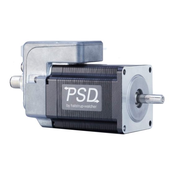
PSD/PSC 4xx positioning system
PSD/PSC 4xx positioning system
The PSD/PSC 4xx positioning system is an integrated drive for the
accurate adjustment of auxiliary and positioning axes. The drive
makes it possible to perform reproducible and simultaneous
adjustments at all the required positions. The PSD/PSC 4xx
positioning system converts a digital positioning signal into a
rotational angle.
The integrated absolute measuring system eliminates the need for
time-consuming reference runs. A bus system connection simplifies
the wiring. A hollow shaft with adjustable collar makes assembly
quite simple.
The positioning system is especially suitable for automatically setting
tools, stops or spindles for wood-processing equipment, packing
lines, printing equipment, filling units and other types of special
machines. The devices require no maintenance.
Models
The PSD/PSC 4xx positioning systems are available in a variety of
models:
-
Torque (options): 0.3 .. 8 Nm
-
Bus interface (options):
o
CA: CANopen (incl. switchable terminating resistor)
o
IO: IO-Link
o
PN: PROFINET
o
EC: EtherCAT
o
EI: EtherNet/IP
o
Others on request
-
Protection class:
o
Standard: IP 50
o
Optional: IP 65
-
Solid circular shaft (flattened), 5 mm or 8 mm
-
Optional: Hollow shaft, 8 mm or 14 mm (with gear reducer)
-
Optional: Gearbox kit with 8 mm or 14 mm hollow shaft
-
Selectable connector orientation (horizontal or vertical with
regard to the output axis)
Adjusting settings
The drive has bus-dependent setting options:
-
Assignment of device address
-
Setting the baud rate
-
Switching the terminating resistor
For more information about these functions and their settings, please
refer to the detailed instruction manual at:
www.halstrup-walcher.de/technicaldocu
Please search for "PSD" or "PSC", select your type, click on
"Instruction manuals" and download the file.
halstrup-walcher GmbH
Stegener Straße 10
79199 Kirchzarten
Germany
Operating elements for drives with hollow shaft
1
M12 male connector for power supply (A-coded)
(for devices with IO-Link also for communication)
2
M12 connector for bus
3
M12 connector for bus
4
Sealing plug: device controls (not for IO-Link)
and status elements
5
Connection diagram: on the adjoining side of the
connectors (not for devices with IO-Link)
6
Housing section with power and control electronics
7
Type label
8
Grounding screw
9
Gearbox with hollow shaft
Illustration exemplary, Models: see order code
Attachment housing with hollow shaft
Illustration exemplary, Models: see order code
10
Hollow shaft, 8 mm or 14 mm, with adjustable collar and
allen screw for spindle mounting
11
Damping plate: to offset lash in the spindle
12
Torque support: mechanical fixation to prevent the drive
from twisting
Tel. +49 7661 39 63-0
info@halstrup-walcher.com
www.halstrup-walcher.com
CA: M12 female connector (B-coded)
EC/PN/EI: M12 female connector (D-coded)
IO: no connector needed
CA: M12 male connector (B-coded)
EC/PN/EI: M12 female connector (D-coded)
IO: no connector needed
© 15/03/2022, Kö
7100.006844
Assembly instruction PSD/PSC 4xx B EN
Advertisement

Related Manuals for halstrup-walcher PSC 4 Series


Summary of Contents for halstrup-walcher PSC 4 Series
- Page 1 Torque support: mechanical fixation to prevent the drive www.halstrup-walcher.de/technicaldocu from twisting Please search for “PSD” or “PSC”, select your type, click on “Instruction manuals” and download the file. halstrup-walcher GmbH © 15/03/2022, Kö Tel. +49 7661 39 63-0 Stegener Straße 10 7100.006844 info@halstrup-walcher.com...
-
Page 2: Safety Precautions
Manufacturer and website Country of manufacture WARNING The drive must only be installed and wired when it is Technical data disconnected from the power supply. Article number (specific) © 15/03/2022, halstrup-walcher - 2 - 7100.006844 Assembly instruction PSD/PSC 4xx B EN... -
Page 3: Installing The Device
4. Now tighten the adjustable collar screw with 4 Nm. The drive is now installed. Note: Ensure that the drive and machine base are as parallel to each other as possible. © 15/03/2022, halstrup-walcher - 3 - 7100.006844 Assembly instruction PSD/PSC 4xx B EN... - Page 4 Please search for “PSD” or “PSC”, select your type, click on “Instruction manuals” and download the files appropriate to your bus communication interface, file name: Connector and pin assignments. © 15/03/2022, halstrup-walcher - 4 - 7100.006844 Assembly instruction PSD/PSC 4xx B EN...
- Page 5 Assembly instruction – PSD4xx positioning system Declaration of Incorporation EU © 15/03/2022, halstrup-walcher - 5 - 7100.006844 Assembly instruction PSD/PSC 4xx B EN...
- Page 6 Assembly instruction – PSD/PSC 4xx positioning system Declaration of Conformity CE © 15/03/2022, halstrup-walcher - 6 - 7100.006844 Assembly instruction PSD/PSC 4xx B EN...
- Page 7 Assembly instruction – PSD/PSC 4xx positioning system Declaration of Incorporation UK © 15/03/2022, halstrup-walcher - 7 - 7100.006844 Assembly instruction PSD/PSC 4xx B EN...
- Page 8 Assembly instruction – PSD/PSC 4xx positioning system Declaration of Conformity UKCA © 15/03/2022, halstrup-walcher - 8 - 7100.006844 Assembly instruction PSD/PSC 4xx B EN...