Table of Contents
Advertisement
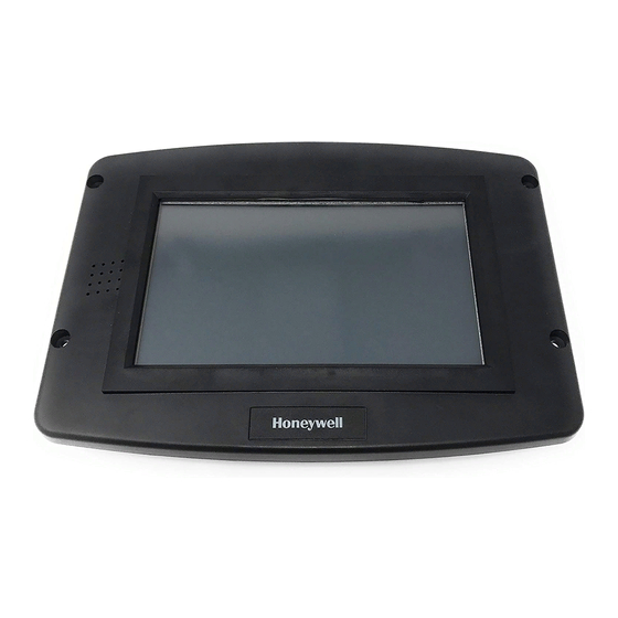
S7999D1048 Combustion System
Operator Interface Display
APPLICATION
The S7999D Combustion System Operator Interface (OI)
reduces burner/boiler setup time by allowing the user to create
a fuel/air modulation curve (profile) for ControLinks
Air Ratio Control) that allows for safe and efficient operation at
all points along the modulation curve. The OI uses a wizard
like process to assist the user through the commissioning
process. The S7999D can be used on systems with one or
two fuels and on systems with or without flue gas re-
circulation (FGR). The S7999D has two RS485 com ports that
can be configured to provide:
• Fuel/Air Ratio Control commissioning and monitoring
• One or more boiler/burner systems monitoring (up to 99
burner/burner systems). Each burner control, Fuel/Air
Ratio Control, and Expanded Annunciator present on each
burner system can be viewed individually to determine its
status.
Specifications ....................................................................
Safety Features .................................................................
Installing the Hardware .....................................................
Networking Options ..........................................................
Getting started .................................................................. 11
Starting the S7999 Display ............................................... 14
Setting up the S7999D display ......................................... 15
Fuel Air Ratio Control Commissioning .............................. 24
Monitoring .......................................................................... 38
• Local display to a System Monitor
• System Monitor to one or more Local displays
• Gateway for ModBus Master (BAS)
Universal Digital Controllers (UDC 2500/3200/3500 with
modbus) can be used for several burner/boiler applications,
and the S7999D can control the UDCs during their operation.
Applications supported include:
• Stack temperature
• Water/steam PID load control
• Steam/fuel flow monitoring
• Thermal shock
• Feed pump level control
The S7999D is a multiple language OI; English and Spanish
selectable.
The S7999D can be flush mount or behind mounted into a
panel cutout.
Wiring connections to the S7999D are through a removable
8-pin wiring connector.
The S7999D also has a USB port that can be used for:
• Transfer screenshot images
• Transfer Trend Analysis Reports
™
(Fuel/
• To upload:
(1) System OI application software revisions (when
(2) Home page background image
(3) Home page logo
(4) Screen saver image
This document provides installation and initial setup
instructions. Other applicable publications are:
• 66-1200 Combustion System Operator Interface
Installation Instructions
Documents can be viewed or downloaded at:
http://customer.honeywell.com
2
Set Hysteresis .................................................................. 42
3
UDC Controllers ............................................................... 44
4
Offline Profile Curve Builder ............................................. 48
5
Renaming the Expanded Annunciator Terminals ............. 52
Troubleshooting ................................................................ 53
UDC Controller Application .............................................. 58
PRODUCT DATA
provided by Honeywell)
Contents
65-0321-01
Advertisement
Table of Contents

Related Manuals for Honeywell S7999D1048


Summary of Contents for Honeywell S7999D1048
-
Page 1: Table Of Contents
S7999D1048 Combustion System Operator Interface Display PRODUCT DATA • Local display to a System Monitor • System Monitor to one or more Local displays • Gateway for ModBus Master (BAS) Universal Digital Controllers (UDC 2500/3200/3500 with modbus) can be used for several burner/boiler applications, and the S7999D can control the UDCs during their operation. -
Page 2: Specifications
TRADELINE® Catalog or price sheets for complete ordering number. If you have additional questions, need further information, or would like to comment on our products or services, please write or phone: 1. Your local Honeywell Environmental and Combustion Controls Sales Office (check white pages of your phone directory). 2. Honeywell Customer Care... -
Page 3: Safety Features
S7999D1048 COMBUSTION SYSTEM OPERATOR INTERFACE DISPLAY [2] 8-15/16 (227) [4] Ø 3/16 [2] 3-1/2 5-15/64 (89) (133) 6-21/32 4-9/16 (169) (116) 7-3/64 (179) 1-5/16 9-7/16 (240) (33) M33567 Fig. 1. S7999D dimensions in in. (mm). NOTE: This equipment has been tested and found to comply with the limits for a Class A digital device, pursuant to part 15 of the FCC Rules. -
Page 4: Installing The Hardware
S7999D1048 COMBUSTION SYSTEM OPERATOR INTERFACE DISPLAY INSTALLING THE HARDWARE Mounting the S7999D — 65-0238 R7999 ControLinks™ Control Controller. — 65-0239 ML7999 ControLinks™ Control Actuator. The S7999D can be mounted on the door panel of an electrical — 65-0240 Q7999 Wiring Subbase. -
Page 5: Networking Options
S7999D1048 COMBUSTION SYSTEM OPERATOR INTERFACE DISPLAY NETWORKING OPTIONS COMMISSIONING THE FUEL/AIR RATIO CONTROL The S7999D has two communication ports (COM1, COM2) that can be set for: In this setup one of the COM ports is set for Fuel/Air Ratio • Fuel/Air Ration Control only (Commission) Control only (commission) •... - Page 6 S7999D1048 COMBUSTION SYSTEM OPERATOR INTERFACE DISPLAY ONE OR MORE BOILER SYSTEMS S7999D OI DISPLAY The S7999D manages a series of Modbus™ nodes (up to 99 addresses) consisting of 7800 SERIES Burner Controls, COM 1 COM 2 24 VAC ControLinks™, and UDC devices (see Fig. 2).
- Page 7 S7999D1048 COMBUSTION SYSTEM OPERATOR INTERFACE DISPLAY UP TO 99 BURNER/BOILER SYSTEMS AND UDC CONTROLLERS S7800 RM78xx SLAVE BURNER UDC2500 SLAVE CONTROL PID LOAD CONTROL RM78xx S7830 R7999 SLAVE S7810M BURNER EXPANDED FUEL AIR MODBUS CONTROL ANNUNCIATOR RATIO CONTROL UDC2500 SLAVE...
- Page 8 S7999D1048 COMBUSTION SYSTEM OPERATOR INTERFACE DISPLAY Careful Modbus™ addressing is required when inserting UDC controllers in this configuration since duplicate addresses S7999D OI DISPLAY aren't allowed. Default Modbus™ addresses for the UDC COM 1 COM 2 24 VAC controllers may need to be changed for them to work properly in the network.
- Page 9 S7999D1048 COMBUSTION SYSTEM OPERATOR INTERFACE DISPLAY Fig. 6 depicts the configuration when this S7999D is a subsystem of the System Modbus™ burner system network. UDC2500 SLAVE THERMAL SHOCK UDC2500 SLAVE PID LOAD CONTROL UDC2500 SLAVE STEAM/FUEL FLOW UDC2500 SLAVE COM 1 OR...
- Page 10 S7999D1048 COMBUSTION SYSTEM OPERATOR INTERFACE DISPLAY System S7999D Configuration Fig. 8 depicts this type of configuration. Only S7999Ds are wired together in this configuration (using either COM port). The S7999D can be configured to monitor all burner/boiler Only one S7999D can be configured as the System S7999D systems via a System Modbus™...
-
Page 11: Getting Started
S7999D1048 COMBUSTION SYSTEM OPERATOR INTERFACE DISPLAY LOCAL S7999D OI DISPLAY COM 1 COM 2 24 VAC POWER SYSTEM S7999D OI DISPLAY COM 1 COM 2 24 VAC POWER LOCAL S7999D OI DISPLAY COM 1 COM 2 24 VAC POWER CONNECT SHIELD TO EARTH GROUND. - Page 12 S7999D1048 COMBUSTION SYSTEM OPERATOR INTERFACE DISPLAY Wiring The S7999D is compatible with R7999 build 140 and newer, and with S7810M build 6020 and newer. The S7999D Display must be appropriately wired for both power and communications. S7999D OI DISPLAY An external 24Vac power source must be supplied for the...
- Page 13 S7999D1048 COMBUSTION SYSTEM OPERATOR INTERFACE DISPLAY Clamp Filters Battery 1. Remove battery compartment cover on back of the dis- To protect against conducted and radiated transient noise, use clamp filters (included in 50063482-001 Bag Assembly). Install play. clamp filters on 24V, COM1, and COM2 wires. See Fig. 12 and Fig.
-
Page 14: Starting The S7999 Display
S7999D1048 COMBUSTION SYSTEM OPERATOR INTERFACE DISPLAY STARTING THE S7999 DISPLAY Home Page The Home page will appear when the device is properly powered. Make sure a screen similar to Fig. 17, 18, or 18 appears after the S7999D is completely powered up. Select the setup button to adjust backlight and sound as desired and for other setup function. -
Page 15: Setting Up The S7999D Display
S7999D1048 COMBUSTION SYSTEM OPERATOR INTERFACE DISPLAY SETTING UP THE S7999D DISPLAY 1. At Home Page, touch Setup Button. The Setup Page is displayed. Fig. 21. Set Date/Time Page. 4. Set the Date and Time and touch OK. 5. When the “Sound audio alarm for fault?” box is checked,... - Page 16 S7999D1048 COMBUSTION SYSTEM OPERATOR INTERFACE DISPLAY Local display to a System Monitor: when this — option is selected, the Com port then becomes a Modbus slave to a System Monitor, see Fig 9. In this figure the Local S7999D IO display would be the Modbus slaves in the Mobus network.
- Page 17 S7999D1048 COMBUSTION SYSTEM OPERATOR INTERFACE DISPLAY UDC2500 SLAVE THERMAL SHOCK UDC2500 SLAVE PID LOAD CONTROL UDC2500 SLAVE STEAM/FUEL FLOW UDC2500 SLAVE STACK UDC2500 TEMPERATURE SLAVE FEED PUMP LEVEL CONTROL RM78xx S7830 SLAVE S7810M BURNER EXPANDED MODBUS CONTROL ANNUNCIATOR LOCAL MODBUS...
- Page 18 S7999D1048 COMBUSTION SYSTEM OPERATOR INTERFACE DISPLAY keyboard is displayed that is used to key in the desired Home title will be in standard font format. The title font size can be Page title. varied from 10F to 24F. Touch the size bar and select the desired font size.
- Page 19 S7999D1048 COMBUSTION SYSTEM OPERATOR INTERFACE DISPLAY Fig. 31. Boiler key variable selection. Fig. 33. Set Password dialog. (In this example, Flame Signal has been selected for the key The Login screen is displayed along with a keyboard to enter variable).
- Page 20 S7999D1048 COMBUSTION SYSTEM OPERATOR INTERFACE DISPLAY corner is a camera icon. When the camera icon is visible, a touch the center of the target. (Instructions are provided at snapshot can be captured of that screen. The Screen the top of the screen). Once the screen has been calibrated Snapshots are available from the Display Diagnostics page.
- Page 21 S7999D1048 COMBUSTION SYSTEM OPERATOR INTERFACE DISPLAY SYSTEM SETUP 1. From the Home Page, touch the “Setup” button. Fig. 38. Screen snapshot menu. 5. Display Reset Touching the “Display Reset” button will reset the S7999D Fig. 39. Setup page. display 2. Ensure that all Modbus network wiring is complete and 6.
- Page 22 S7999D1048 COMBUSTION SYSTEM OPERATOR INTERFACE DISPLAY e. The “Modbus Configuration” button provides an advanced troubleshooting function that allows the user to read and write to individual Modbus registers. The user can read and write any Modbus register in the S7810M Modbus Module or UDC controller.
- Page 23 S7999D1048 COMBUSTION SYSTEM OPERATOR INTERFACE DISPLAY The table below lists the possible selections the user can choose for display. See “UDC Controller Status” on page 45 for details to select the "Key Variables". Table 2. Home Page UDC Status Variables...
-
Page 24: Fuel Air Ratio Control Commissioning
S7999D1048 COMBUSTION SYSTEM OPERATOR INTERFACE DISPLAY Table 3. S7999D Home Page Status Variables Burner/boiler system component Status variable Burner Control Sequence state Burner Control Fault code Burner Control Flame Signal Strength R7999 Fuel selection R7999 Fault code R7999 Firing rate... - Page 25 S7999D1048 COMBUSTION SYSTEM OPERATOR INTERFACE DISPLAY Table 4. Commissioning Overview. (Continued) Step Action Notes 4.a. Select the base configuration. The choices are: • Unconfigured: selecting this option takes the device back to a factory state and sets the password to “password”.
- Page 26 1 degree if it is unconfigured. When used with Honeywell burner controls, the user has 240 seconds to perform this action, otherwise the burner control will lock out.
- Page 27 S7999D1048 COMBUSTION SYSTEM OPERATOR INTERFACE DISPLAY Table 4. Commissioning Overview. (Continued) Step Action Notes 12.k. Press Open and Close for Fuel and Air and the FGR (if present) For gas systems of which the gas pressure has not to move the cursor to the Maximum Modulation point for the been adjusted to match the burner-rated BTU burner.
- Page 28 S7999D1048 COMBUSTION SYSTEM OPERATOR INTERFACE DISPLAY NOTE: Clicking the Home, Back or Monitor button will exit Commissioning mode and display the Home page. Password You must enter the R7999 Commission password into the system (Fig. 47). The password consists of a minimum of four characters/numbers and a maximum of ten characters/ numbers.
- Page 29 S7999D1048 COMBUSTION SYSTEM OPERATOR INTERFACE DISPLAY The user can choose to end the commissioning process before the actuator has been configured, a checkmark is displayed next to the appropriate button. See Fig. everything is finished, and, if so, this page has the appearance of the following two figures (Fig.
- Page 30 S7999D1048 COMBUSTION SYSTEM OPERATOR INTERFACE DISPLAY Actuator Serial Number NOTE: You must resend the KEY (serial number) any time you revise the closed direction setting or change This page (Fig. 52) allows the user to enter the serial number the type of end-stop selection.
- Page 31 S7999D1048 COMBUSTION SYSTEM OPERATOR INTERFACE DISPLAY between the max and min modulation points on a curve for a valid profile, except for builds 185 and higher. b. Lightoff—Press to save the lightoff position on the graph. An ‘L’ is displayed on the graph to indicate the lightoff point.
- Page 32 S7999D1048 COMBUSTION SYSTEM OPERATOR INTERFACE DISPLAY Quit • Press this button when done with the curve at this point. The following buttons display: a. Back: • Press to return to the Commission Configuration screen. b. Home: • Go to Home page.
- Page 33 S7999D1048 COMBUSTION SYSTEM OPERATOR INTERFACE DISPLAY Fig. 60. Completed Commissioning Curve. Fig. 63. Quit Commissioning Finish. System Parameters NOTE: All System Parameter pages are disabled until all actuators are configured. 1. Press the System Configuration button on the Commission Configuration screen to set system parameters.
- Page 34 S7999D1048 COMBUSTION SYSTEM OPERATOR INTERFACE DISPLAY Auxiliary Sensor Configuration c. Threshold—This field lets you set the threshold tem- perature at which you want the low fire hold or FGR The first page that displays after the “System Configuration” hold or Low Fire and FGR hold to be released. The button is selected is shown in Fig.
- Page 35 S7999D1048 COMBUSTION SYSTEM OPERATOR INTERFACE DISPLAY Actuator Standby Positions (Presets) Table 5. Default Values/Settings for System Parameters Parameter Default Threshold Differential Controller Timing Postpurge time 30 seconds Automanual Switch Automanual Switch Normal Mode Program Standby Position Fuel Selection 1 Fuel...
- Page 36 S7999D1048 COMBUSTION SYSTEM OPERATOR INTERFACE DISPLAY Fig. 70. Advanced Options—Reset Factory Defaults. Fig. 71. EEPROM Maintenance—No image. If EEPROM images exist, the name assigned to the images, Fuel/Air Ratio Control EEPROM the R7999 build associated with the images, the date and time...
- Page 37 S7999D1048 COMBUSTION SYSTEM OPERATOR INTERFACE DISPLAY If the EEPROM images don’t match with the R7999 build, an error is displayed and no uploading is permitted. To download the R7999 EEPROM data to the S7999D, the “Download EEPROM” image button is selected. The user is asked to confirm that this action should proceed.
-
Page 38: Monitoring
74) before proceeding. “View” button. MONITORING The Honeywell devices attached to the burner system are represented by icon buttons on the Home page. To obtain status information about each device, the user selects the button that corresponds to the device. A new page displays with status information exclusively about that device. - Page 39 S7999D1048 COMBUSTION SYSTEM OPERATOR INTERFACE DISPLAY If the burner control is currently in a lockout condition, the lockout cause is displayed on the screen (Fig. 77). The lockout fault is also visible in the fault history. If audio alarm is enabled for fault conditions (see “Setting up the S7999D display”...
- Page 40 S7999D1048 COMBUSTION SYSTEM OPERATOR INTERFACE DISPLAY The “Show Faults” button displays the burner control fault history (Fig. 82). This button has a red color when the burner control is currently in a fault (lockout) condition. Fig. 84. Expanded Annunciator Status.
- Page 41 S7999D1048 COMBUSTION SYSTEM OPERATOR INTERFACE DISPLAY Fig. 87. Fuel/Air Ratio Control—Fault History, right view. Fig. 85. Fuel/Air Ratio Control Status. The Fuel/Air Ratio Control faults history can be viewed by Fuel/Air Ratio Control Configuration selecting the “Show Faults” button (Fig. 86). This button has a...
-
Page 42: Set Hysteresis
S7999D1048 COMBUSTION SYSTEM OPERATOR INTERFACE DISPLAY Fig. 89. Fuel Preset Settings. Fig. 92. Fuel/Air Ratio Control Fault History, right view. The “Diagnostics” button displays diagnostic information about Set Hysteresis the Fuel/Air Ratio Control (Fig. 90). Current hysteresis value can be viewed or changed by selecting the “Hysteresis” button. - Page 43 S7999D1048 COMBUSTION SYSTEM OPERATOR INTERFACE DISPLAY For Modbus™ burner systems (when the Fuel/Air Control is connected to the S7810M Modbus Module), some of this information is not available: Key, Stop Type, Close Direction, and State. This information is blank on the screen in this case.
-
Page 44: Udc Controllers
S7999D1048 COMBUSTION SYSTEM OPERATOR INTERFACE DISPLAY When the “Control Accuracy” button is selected, a new page (Fig. 100) is displayed. Pressing the Set Accuracy button causes the Fuel/Air Control to reset and store the user- selected value in the Fuel/Air Control nonvolatile memory. - Page 45 S7999D1048 COMBUSTION SYSTEM OPERATOR INTERFACE DISPLAY configuration, the alarm text and LED are grayed out. The alarm setpoints can be adjusted with the Up Arrow and Down Arrow buttons to increase or decrease the setting. Below each alarm and input reading are Key buttons that allow the corresponding status to be selected as a key variable for display on the Home page.
- Page 46 S7999D1048 COMBUSTION SYSTEM OPERATOR INTERFACE DISPLAY temperature or steam pressure input, but not both, based on the UDC controller model. UDC controllers that can have more than one con- current sensor input, such as the Steam/Fuel Flow Monitor, only display one of the sensors at a time.
- Page 47 S7999D1048 COMBUSTION SYSTEM OPERATOR INTERFACE DISPLAY PID Load Controller If a Low Fire Hold alarm is configured in the UDC controller, the setpoint of this alarm is obtained from the UDC controller and Current load water temperature or steam pressure is obtained displayed on the page.
-
Page 48: Offline Profile Curve Builder
S7999D1048 COMBUSTION SYSTEM OPERATOR INTERFACE DISPLAY Flow Monitor The user can adjust the control setpoint on the page. The status of the shock alarm (when water supply temperature falls If steam flow is configured in the UDC controller, current steam... - Page 49 S7999D1048 COMBUSTION SYSTEM OPERATOR INTERFACE DISPLAY • “View”—to view the currently selected curve in a fuel/air • Select the Fuel% text box and adjust the open percentage ratio graph. for the fuel actuator. • “Copy”—to copy the currently selected curve to another one •...
- Page 50 S7999D1048 COMBUSTION SYSTEM OPERATOR INTERFACE DISPLAY Fig. 118. Edit Profile Curve. Fig. 116. Edit Profile Curve. Fig. 119. Edit Air Percentage. Fig. 117. Curve View. To insert a new point in the curve: Edit Curve • Select a point in the point list above or below the new point To edit a profile curve, select the curve in the list on the left side values you wish to insert.
- Page 51 S7999D1048 COMBUSTION SYSTEM OPERATOR INTERFACE DISPLAY Delete Curve To delete a curve, select the curve to delete from the curve list on the left side of the screen (Fig. 112). Select the “Delete” button and a dialog box displays, asking the user to confirm the delete (Fig.
-
Page 52: Renaming The Expanded Annunciator Terminals
S7999D1048 COMBUSTION SYSTEM OPERATOR INTERFACE DISPLAY variable. These static assignments can be saved to permanent The user touches the "Change Description" button to change storage (flash) and are the default assignments when the the current setting. A keyboard window with the current setting S7999D is powered up. -
Page 53: Troubleshooting
S7999D1048 COMBUSTION SYSTEM OPERATOR INTERFACE DISPLAY TROUBLESHOOTING No Burner Control, Expanded Annunciator, R7999, UDC Controller Buttons • Check wiring between S7999D and S7810M. Make sure that S7810M terminal 7 (A) is connected to S7999D terminal A (of the COM port that has been configured for "One or more boiler systems"),... - Page 54 S7999D1048 COMBUSTION SYSTEM OPERATOR INTERFACE DISPLAY Burner Control Locks Out Due to a. If no fuel select inputs are on, or both fuel selects are made, you cannot establish communications with the Loss of Air Flow Switch controller. The corrective action is to select one of the fuels or remove one of the fuel select inputs.
- Page 55 S7999D1048 COMBUSTION SYSTEM OPERATOR INTERFACE DISPLAY Table 7. Fault Codes and Corrective Actions. (Continued) Fault/ Blink Code Description Corrective Action Internal Error – KEY decode. Reset Control Internal Error – Rdlow. Reset Control Internal Error – Time storage. Reset Control Internal Error –...
- Page 56 S7999D1048 COMBUSTION SYSTEM OPERATOR INTERFACE DISPLAY Table 7. Fault Codes and Corrective Actions. (Continued) Fault/ Blink Code Description Corrective Action Actuators not reaching lightoff point. Check for actuator wiring problems or stuck valves/dampers. Place controller in standby and use actuator manual keys to verify actuator travel.
- Page 57 S7999D1048 COMBUSTION SYSTEM OPERATOR INTERFACE DISPLAY Table 7. Fault Codes and Corrective Actions. (Continued) Fault/ Blink Code Description Corrective Action The 4 to 20 mA firing rate input is below 3 mA, Out of Check CmA+- input (Terminals 39 and 40) for proper operation Range—Low.
-
Page 58: Udc Controller Application
S7999D1048 COMBUSTION SYSTEM OPERATOR INTERFACE DISPLAY R7999 OUTPUTS AND INPUTS The current state of the R7999 outputs and inputs are displayed on the Monitor screen for convenience and diagnostics purposes. The inputs and outputs are defined as follows: Table 8. Outputs. - Page 59 S7999D1048 COMBUSTION SYSTEM OPERATOR INTERFACE DISPLAY APPLICATION NOTE Application: Steam Pressure Load Control Description: On-off and modulating outputs to start/stop and adjust firing rate to maintain a control setpoint. FIRING RATE MOTOR CONTROLLER INTERFACE 250 OHM RESISTOR SHIELD ON–OFF CONTROL...
- Page 60 S7999D1048 COMBUSTION SYSTEM OPERATOR INTERFACE DISPLAY Controller Model (see footnote) Algorithm: CTRALG PIDA PIDA PIDA PIDA PIDA PIDA PIDA PIDA TIMER Output: OUTALG CURRENT CURRENT CURRENT CURRENT CURRENT CURRENT CURRENT CURRENT Input 1: IN1TYP 4–20 mA 4–20 mA 4–20 mA 4–20 mA...
- Page 61 S7999D1048 COMBUSTION SYSTEM OPERATOR INTERFACE DISPLAY APPLICATION NOTE Application: Water Temperature Load Control Description: On-off and modulating outputs to start/stop and adjust firing rate to maintain a control setpoint. FIRING RATE MOTOR CONTROLLER INTERFACE LOW FIRE HOLD CONTROL CIRCUIT SHIELD ON–OFF CONTROL...
- Page 62 S7999D1048 COMBUSTION SYSTEM OPERATOR INTERFACE DISPLAY Algorithm: CTRALG PIDA PIDA PIDA PIDA TIMER Output: OUTALG CURRENT CURRENT CURRENT CURRENT Input 1: IN1TYP 100H 100H 100H 100H IN1 HI 1200 1200 1200 1200 IN1 LO -300 -300 -300 -300 Input 2:...
- Page 63 S7999D1048 COMBUSTION SYSTEM OPERATOR INTERFACE DISPLAY APPLICATION NOTE Application: Stack Temperature Description: Monitor stack temperature and alarm when temperature is too high. Optionally output an FGR permissive signal when stack temperature reaches permitted level. CONTROLLER FLUE GAS PERMISSIVE CIRCUITRY SHIELD...
- Page 64 S7999D1048 COMBUSTION SYSTEM OPERATOR INTERFACE DISPLAY IN1 HI IN1 LO Input 2: IN2TYP DIS (Disable) DIS (Disable) Control: LSP’S SP TRK NONE NONE PWR UP ALSP ALSP SP Hi SP Lo ACTION HYST Options: AUXOUT DIGIN1 NONE NONE DIGIN2 NONE...
- Page 65 S7999D1048 COMBUSTION SYSTEM OPERATOR INTERFACE DISPLAY APPLICATION NOTE Application: Thermal Shock Description: Modulate a hydronic mixing valve (or pump) to maintain an optimal boiler supply water temperature. CONTROLLER FIRING RATE MOTOR INTERFACE SHIELD ALARM (LOW RTD SENSOR INLET TEMP) 100 OHM...
- Page 66 S7999D1048 COMBUSTION SYSTEM OPERATOR INTERFACE DISPLAY IN1 LO -300 Input 2: IN2TYP Control: LSP’S 1 ONLY SP TRK NONE PWR UP ALSP SP Hi SP Lo ACTION HYST Options: AUXOUT DIGIN1 NONE DIGIN2 NONE Communications: ComADR ComSTA MODB BAUD 19.2K...
- Page 67 S7999D1048 COMBUSTION SYSTEM OPERATOR INTERFACE DISPLAY APPLICATION NOTE Application: Flow Monitor Description: Monitoring and display of steam flow (pounds of steam per hour) or fuel flow (cubic feet or gallons per hour) with totalization calculation options. UDC 3500 CONTROLLER 250 OHM...
- Page 68 S7999D1048 COMBUSTION SYSTEM OPERATOR INTERFACE DISPLAY TIMER Output: OUTALG CURRENT CURRENT CURRENT CURRENT CURRENT CURRENT CURRENT CURRENT CURRENT CURRENT Input 1: IN1TYP 4-20 4-20 4-20 4-20 4-20 4-20 4-20 4-20 4-20 4-20 IN1 HI IN1 LO Input 2: IN2TYP 4-20...
- Page 69 S7999D1048 COMBUSTION SYSTEM OPERATOR INTERFACE DISPLAY APPLICATION NOTE Application: Feed Pump Description: Monitor digital inputs to start and stop boiler feedwater and to alarm an open circuit on high water condition. Digital Inputs: Digital Outputs: None Start-Stop relay (ON when Start boiler in...
- Page 70 S7999D1048 COMBUSTION SYSTEM OPERATOR INTERFACE DISPLAY 65-0321—01...
- Page 71 Fig. 129. S7999D front-mount cutout template. 65-0321—01...
- Page 72 S7999D1048 COMBUSTION SYSTEM OPERATOR INTERFACE DISPLAY 65-0321—01...
- Page 73 Fig. 130. S7999D rear-mount cutout template. 65-0321—01...
- Page 74 S7999D1048 COMBUSTION SYSTEM OPERATOR INTERFACE DISPLAY 65-0321—01...
- Page 75 S7999D1048 COMBUSTION SYSTEM OPERATOR INTERFACE DISPLAY 65-0321—01...
- Page 76 S7999D1048 COMBUSTION SYSTEM OPERATOR INTERFACE DISPLAY Automation and Control Solutions Honeywell International Inc. 1985 Douglas Drive North ® U.S. Registered Trademark Golden Valley, MN 55422 © 2012 Honeywell International Inc. 65-0321—01 M.S. 08-12 customer.honeywell.com Printed in United States...