
Related Manuals for Honeywell NOTIFIER LCD-160


Summary of Contents for Honeywell NOTIFIER LCD-160
- Page 1 Liquid Crystal Display LCD-160 Manual Document 51850 10/07/2016 Rev: P/N 51850:D2 ECN 16-0219...
- Page 2 Fire Alarm & Emergency Communication System Limitations While a life safety system may lower insurance rates, it is not a substitute for life and property insurance! An automatic fire alarm system—typically made up of smoke (caused by escaping gas, improper storage of flammable materi- detectors, heat detectors, manual pull stations, audible warning als, etc.).
- Page 3 HARSH™, NIS™, NOTI•FIRE•NET™, and eVance™ are all trademarks; and Acclimate® Plus™, FlashScan®, FAAST Fire Alarm Aspiration Sensing Technology®, Intelligent FAAST®, NOTIFIER®, ONYX®, ONYXWorks®, SWIFT®, VeriFire®, and VIEW® are all registered trademarks of Honeywell International Inc. Microsoft® and Windows® are registered trademarks of the Microsoft Corporation. Chrome™ and Google™ are trademarks of Google Inc.
- Page 4 •Brief description of content you think should be improved or corrected •Your suggestion for how to correct/improve documentation Send email messages to: FireSystems.TechPubs@honeywell.com Please note this email address is for documentation feedback only. If you have any technical issues, please contact Technical Services.
-
Page 5: Table Of Contents
Table of Contents Table of Contents Section 1: About this Manual....................7 1.1: Notes, Cautions, and Warnings........................7 1.2: Typographic Conventions ..........................7 Section 2: Installation Standards and Codes................. 8 2.1: Related Documentation ..........................8 2.2: UL 9th Edition Compliance...........................8 Section 3: System Overview ....................9 3.1: Introduction to the LCD-160 .........................9 3.2: Features and Specifications ...........................9 3.2.1: Features..............................9... - Page 6 Table of Contents 9.1.3: LCD Display ............................32 9.1.4: Programming Confirmation Dialog ....................34 9.2: Operating Screens ............................34 9.2.1: Event Counts Display ........................34 9.2.2: More Information..........................36 9.2.3: Multiple Event List Display.......................37 9.3: Service Screens ............................39 9.3.1: Version Information...........................39 9.3.2: Power-up Screen ..........................40 9.3.3: Download Screen..........................40 9.3.4: Download Application Screen ......................41 9.3.5: Download Bootloader Screen ......................41...
-
Page 7: Section 1: About This Manual
Section 1: About this Manual 1.1 Notes, Cautions, and Warnings This manual contains notes, cautions, and warnings to alert the reader as follows: NOTE: Supplemental information for a topic, such as tips and references. NOTE: Information about procedures that could cause programming errors, runtime errors, or equipment damage. -
Page 8: Section 2: Installation Standards And Codes
Section 2: Installation Standards and Codes The LCD-160 is designed to comply with the following standards: NFPA 72 National Fire Alarm Code Underwriters Laboratories: • UL 864 Standard for Control Units and Accessories for Fire Alarm Systems • UL 1076 Standard for Proprietary Burglar Alarm Units and Systems •... -
Page 9: Section 3: System Overview
Section 3: System Overview 3.1 Introduction to the LCD-160 The LCD-160 is a 240 x 128 pixel annunciator for NOTIFIER fire security control panels and network control annunciators. The LCD-160 can mimic the top half of the panel’s display, or it can display custom messages or graphics. -
Page 10: Product Diagram
System Overview Product Diagram 3.3 Product Diagram Board Layout The LCD-160 board layout is illustrated in Figure 3.1. J1 Key Switch See Figure 6.8 (Future) Power See Figure 6.6 +24 VDC +24 VDC COMMON LED11 COMMON Status +RDP +RDP –RDP –RDP LED14 EARTH... -
Page 11: Installation Overview
Installation Overview System Overview Diagnostic LED Indicators LED indicators 11 through 14 aid in troubleshooting the LCD-160 and are visible to the installer only. Figure 3.1 shows the locations of the diagnostic LED indicators. Table 3.1 lists and describes the function of each of these diagnostic LED indicators. LED Indicators 1 through 10 indicate system status and are visible to the user. -
Page 12: Section 4: Hardware
Section 4: Hardware This section is intended as a basic inventory of components that can be used with the LCD-160. 4.1 Backboxes NOTE: For Canadian Applications, only the ABS-2DC, ABS-4DC, and the CAB-4 Series cabinets are approved for LCD-160 installation. These backboxes provide a surface or semi-flush mount enclosure for remote mounting. -
Page 13: Additional Hardware
Additional Hardware Hardware Part Optional Height Width Depth Color Number Trim Ring C-Size 37.250 in (94.62 cm) 24.125 in (61.28 cm) 5.218 in (13.25 cm) TR-C4 (3 rows) D-Size 45.875 in (116.52 cm) 24.125 in (61.28 cm) 5.218 in (13.25 cm) TR-D4 (4 row) Table 4.1 Backbox Sizing Guide... - Page 14 Hardware Additional Hardware The Annunciator Key Switch provides access security for the control switches on AKS-1B, AKS-1 the LCD-160. The key switch kit includes a key and hardware for mounting to the trim plate of a flush-mount type annunciator enclosure. An adhesive-backed Annunciator Label for use with the key switch/dress plate assembly is also included.
-
Page 15: Section 5: Mounting
Section 5: Mounting This section describes how to mount the LCD-160 into an enclosure. WARNING: USE A GROUNDING STRAP BEFORE HANDLING ANY CIRCUITS SO THAT STATIC CHARGES ARE REMOVED FROM THE BODY. 5.1 Mount the Cabinet or Backbox Select an appropriate knockout on the enclosure for your wiring to run through and snap it out. -
Page 16: Section 6: Wiring
Section 6: Wiring This section explains how to wire the LCD-160 for communication, power, and security. 6.1 Overview WARNING: REMOVE ALL POWER SOURCES TO EQUIPMENT WHILE CONNECTING ELECTRICAL COMPONENTS. LEAVE THE EXTERNAL, MAIN POWER BREAKER OFF UNTIL INSTALLATION OF THE ENTIRE SYSTEM IS COMPLETE. WARNING: SEVERAL SOURCES OF POWER CAN BE CONNECTED TO THE CONTROL PANEL. -
Page 17: The Rdp Bus
The RDP Bus Wiring 6.2 The RDP Bus 6.2.1 Wire Runs Communication between the control panel and any RDP device, such as the LCD-160, occurs over an RDP interface. This communication is supervised by the panel and the LCD-160. The RDP bus can drive up to 32 RDP devices. The fire panel or network control annunciator must be at one end of the bus and an end-of-line resistor must be enabled on the last RDP device on the circuit. -
Page 18: 3: Shielding The Rdp Bus
Wiring The RDP Bus 6.2.3 Shielding the RDP Bus All enclosures, including the panel backbox, must be connected to earth ground! Never use the shield for grounding purposes. If shielded, terminate the RDP shield at one end only. • When the RDP shield is in conduit: Connect it to a system reference (system common). The shield can enter the cabinet, but it must be insulated from the cabinet (no electrical contact). -
Page 19: Earth Ground
Earth Ground Wiring NOTE: Switches 3 and 4 MUST remain disabled. The End-of-Line Resistor is disabled. Switch 2 is OFF. The slider is away from the display screen. LCD160SW17.wmf LDC160SW17location.wmf Figure 6.4 SW17 (ELR Disabled) 6.3 Earth Ground During mounting (see Section 5.1), the backbox or cabinet should have been connected to a solid earth... -
Page 20: Power Supply Connections
Wiring Power Supply Connections 6.4 Power Supply Connections The LCD-160’s 24 VDC power source must be TB2 PWR Supply regulated, filtered, non-resettable, and listed for fire- protective signaling use. Sources include main power supplies, auxiliary power supplies, and panels with integrated power supplies. -
Page 21: Connecting The Annunciator Key Switch
Connecting the Annunciator Key Switch Wiring Remote Power Supply LCD-160 Power Loop Ground fault Common Reference detection disabled. Two-wire When more than one power supply is RDP bus used on an RDP bus, a common reference connection must be established and only one supply can have ground fault detection enabled. -
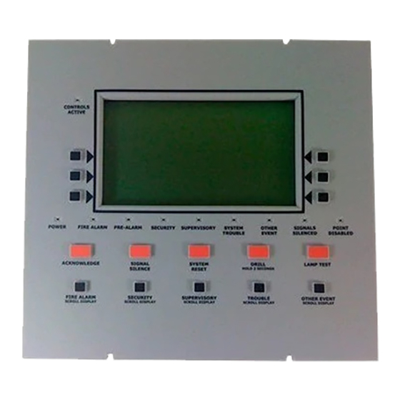
Page 22: Section 7: The Lcd-160 Interface
Section 7: The LCD-160 Interface Soft Keys Status LEDs Note: Drill is replaced with Alarm Signal for Canadian applications. Fixed Function Keys Figure 7.1 The LCD-160 Keypad 7.1 The Liquid Crystal Display The display is 40 characters wide by 16 lines. It displays all programming screens, as well as other information. -
Page 23: 2: Fixed Function Keys
The Keypad The LCD-160 Interface 7.2.2 Fixed Function Keys The ten keys labeled on the front of the LCD-160 are fixed function keys. If there is an active command center and DCC is enabled at the panel, Acknowledge, Signal Silence, System Reset, and Drill require permission before they can be processed. -
Page 24: 3: Status Led Indicators
The LCD-160 Interface The Keypad 7.2.3 Status LED Indicators There are nine labeled LEDs aligned along the bottom of the display, and one LED at the upper left corner of the display. They light to annunciate certain conditions, as described in Table 7.1 below. LED INDICATOR COLOR FUNCTION... -
Page 25: Section 8: Event Handling
Section 8: Event Handling 8.1 About Events An event is a change in the status of a device, a transfer of information between a device and the LCD-160, or a transfer of information between two devices. Some events are considered background and housekeeping events and are not seen by the user. - Page 26 Event Handling About Events Line 1 F I R E A L A R M Event E L E V A T O R L O B B Y E A S T W I N G Format Displays the type of F I F T H F L O O R Z 2 3 9 S M O K E ( P H O T O )
-
Page 27: The Display And Control Center (Dcc)
The Display and Control Center (DCC) Event Handling System Events Format When a system trouble occurs, a message, generated by the control panel, displays at the top of the LCD-160’s screen, while soft keys display available functions that may be used to handle the event. The top four lines contain event information, and are formatted as follows: Line 1 - Displays TROUBLE and whether it has been... - Page 28 Event Handling The Display and Control Center (DCC) (Figure ). If no DCC already exists, the command is processed and the acknowledging LCD-160 assumes control. An LCD-160 can only assert control over its associated panel. When a specific LCD-160 assumes control the LED illuminates.
-
Page 29: Event Handling
Event Handling Event Handling 8.3 Event Handling When an event comes in, the piezo will sound (if enabled), the appropriate LED indicator will flash, and the Event Counts Screen will automatically display with the highest priority active event appearing at the upper left corner of the screen. If an event occurs while the Multiple Event Count List is active, lines one through four will display the unacknowledged event and line five will read PRESS ANY KEY. -
Page 30: Section 9: Screen Displays
Section 9: Screen Displays 9.0.1 The Main Menu The “Main Menu” screen is the means by which the programmer can access displays and programming menus. This screen displays upon power up. It is accessible via the soft MAIN MENU key on the “Graphic Screen”, the “Event List” screen and from most other screens by pressing the soft key until it displays. -
Page 31: Programming Screens
Programming Screens Screen Displays L A K E S I D E G E N E R A L H O S P I T A L S Y S T E M N O R M A L 1 1 : 5 8 : 4 5 A T U E J A N 1 2 , 2 0 1 6 M A I N M E N U Figure 9.2 Graphic Screen (No Off-Normal Events) -
Page 32: 2: Panel Program Menu
Screen Displays Programming Screens Programming screens, such as “Panel Programming” and “LCD Display” are not available unless the programming switch is enabled. Once programming is completed, the switch must be “locked” back into the non-programming position. NOTE: Enabling the programming switch will cause a “Remote Display” trouble. 9.1.2 Panel Program Menu Pressing the soft key to the right of on the “Main Menu”... - Page 33 Programming Screens Screen Displays L C D D I S P L A Y L C D I N T E N S I T Y : 4 0 % B R I G H T E R D E F A U L T D A R K E R A C C E P T B A C K L I G H T : O N E X C E P T A C F A I L...
-
Page 34: 4: Programming Confirmation Dialog
Screen Displays Operating Screens 9.1.4 Programming Confirmation Dialog P A N E L P R O G R A M M E N U T H I S A C T I O N W I L L R E P R O G R A M T H E D A T A B A S E D O N O T P O W E R O F F A R E Y O U S U R E ? Y E S... - Page 35 Operating Screens Screen Displays A C K N O W L E D G E D T R O U B L E N O A N S W E R E L E V A T O R L O B B Y E A S T W I N G F I F T H F L O O R Z 0 0 5...
-
Page 36: 2: More Information
Screen Displays Operating Screens 9.2.2 More Information Pressing the soft key to the left of on the “Event Counts Display” brings up MORE INFORMATION the “More Information” screen. This screen contains additional information about the event shown in the Event Reporting Format. A C K N O W L E D G E D F I R E A L A R M E L E V A T O R L O B B Y E A S T W I N G... -
Page 37: 3: Multiple Event List Display
Operating Screens Screen Displays Message Description Replace/Malfunction Replace the defective detector. The detector may not operate properly. None/Very Clean No action necessary. The detector readings are near ideal. None/Clean No action necessary. Although not ideal, the detector will activate at the selected sensitivity level. None/Fairly Clean No action necessary. - Page 38 Screen Displays Operating Screens With Fire as the highest priority: With MNS as the highest priority: USA Event Order Canada Event Order USA Event Order Canada Event Order Fire Fire MN Alarm CO Alarm CO Alarm Fire Fire MN Alarm CO Alarm CO Alarm CO Pre-alarm...
-
Page 39: Service Screens
Service Screens Screen Displays A C K N O W L E D G E D F I R E A L A R M E L E V A T O R L O B B Y E A S T W I N G F I F T H F L O O R Z 0 0 5 S M O K E ( P H O T O ) -
Page 40: 2: Power-Up Screen
Screen Displays Service Screens 9.3.2 Power-up Screen The Power-up screen appears when the panel is powering up. During power-up, a series of self- tests are performed internally: the tests and the results of the tests appear on the screen as they are completed. -
Page 41: 4: Download Application Screen
Service Screens Screen Displays 9.3.4 Download Application Screen This screen is displayed during application downloads. Downloading is initiated at the panel. The progress meter shows the progress of the current download. T R O U B L E L O A D I N G . . N O S E R V I C E A 0 1 L C D - 1 6 0 B O O T L O A D E R U P D A T I N G L C D - 1 6 0 A P P L I C A T I O N... -
Page 42: 7: Application Corrupt Screen
Screen Displays Service Screens T R O U B L E L O A D I N G . . N O S E R V I C E A 0 1 L C D - 1 6 0 B O O T L O A D E R L C D - 1 6 0 D O W N L O A D M E N U U P D A T I N G L C D - 1 6 0 S T R I N G S D O W N L O A D I N G . - Page 43 Appendix A: LCD-160 Power Requirements An LCD-160 draws its power from the power supply and must be considered when calculating the primary and secondary power supply requirements for the system. Each LCD-160 is accounted for in the power calculations outlined in the respective installation manual. However, if the current draw dedicated to all LCD-160s must be calculated as a separate figure, use the equations in Table A.1.
-
Page 44: Index
Index and Power-up screen 40 fixed function key 23 ABF-2B 12 ABF-4B 12 ABS-2D 12 ABS-2DR 12 Earth Ground 19 ABS-4D 12 Electrical connections 16 ABS-4DR 12 Electrical ratings 43 Acknowledge ELR, see End-of-Line Resistor block and point 29 End-of-Line Resistor 18 fixed function key 23 Event counts 26 Action/Status, detector 36... - Page 45 Index N–W Microfail, LED indicator 11 MNS Alarm Event 29 Scroll Back 39 More Information (screen) 36 SCROLL/DISPLAY keys 23 Mounting 15 Security events 29 Multiple Event List Display 37 event format 26 Multiple power supplies 21 LED indicator 24 SCROLL/DISPLAY key 23 Self-Test Screen see Power-Up Screen –...
- Page 46 W–W Index Power-limited (Class 2) 16 RDP 17 LCD-160 Manual — P/N 51850:D2 10/07/2016...
- Page 47 Manufacturer Warranties and Limitation of Liability Manufacturer Warranties. Subject to the limitations set forth herein, Manufacturer warrants that the Products manufactured by it in its Northford, Connecticut facility and sold by it to its authorized Distributors shall be free, under normal use and service, from defects in material and workmanship for a period of thirty six months (36) months from the date of manufacture (effective Jan.
- Page 48 World Headquarters 12 Clintonville Road Northford, CT 06472-1610 USA 203-484-7161 fax 203-484-7118 www.notifier.com...