
Related Manuals for Honeywell Notifier LCD2-80


Summary of Contents for Honeywell Notifier LCD2-80
- Page 1 vm vm Liquid Crystal Display LCD2-80 Instruction Manual Document 53242 08/18/2009 Rev: P/N 53242:A ECN 09-496...
- Page 2 Fire Alarm System Limitations While a fire alarm system may lower insurance rates, it is not a substitute for fire insurance! An automatic fire alarm system—typically made up bed, and violent explosions (caused by escaping gas, of smoke detectors, heat detectors, manual pull sta- improper storage of flammable materials, etc.).
- Page 3 ONYXWorks®, UniNet® VeriFire® VIEW® , and are all registered trademarks of Honeywell International Inc. Acclimate® Plus, SpectrAlert® and System Sensor® are all registered trademarks of Echelon® Honeywell International Inc. Silent Knight® is a registered trademark of Honeywell International Inc. LonWorks™ ARCNET®...
- Page 4 • Brief description of content you think should be improved or corrected • Your suggestion for how to correct/improve documentation Send email messages to: FireSystems.TechPubs@honeywell.com Please note this email address is for documentation feedback only. If you have any technical issues, please contact Technical Services.
-
Page 5: Table Of Contents
Table of Contents Section 1: Product Overview ..........6 1.1: UL 864 Compliance................6 1.1.1: Products Subject to AHJ Approval ..........6 1.1.2: Programming Features Subject to AHJ Approval ......6 1.2: Features....................7 Section 2: The LCD2-80 & Terminal Mode......9 2.1: Operating the LCD2-80 in Terminal Mode ........11 2.1.1: Display Patterns ................11 2.1.2: Switch Functions.................11 2.1.3: LED Functions ................12... -
Page 6: Section 1: Product Overview
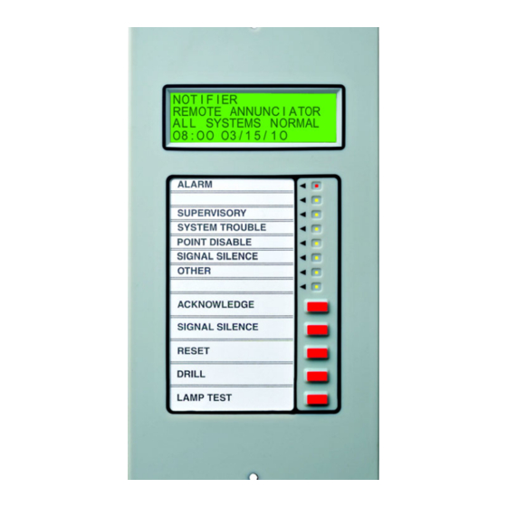
Section 1: Product Overview The LCD2-80 alphanumeric display module is an ancillary device used by Notifier fire alarm control panels including NCA-2, NFS-320, NFS2-640, and NFS2-3030. The product operates in Terminal mode, where it acts as a Display Interface. NOTE:The LCD2-80 should not be used as a primary display in Canada. -
Page 7: Features
Features Product Overview 1.2 Features • 80-character backlit LCD display. • Control switches for Acknowledge, Signal Silence, Drill and System Reset. • Time/date display field. • ABF-1/B package with key switch option. • Mounts up to 6000 foot segments between units. •... - Page 8 Product Overview Features DIP Switch Settings (SW3) Refer to Figure 2.1 for details. Address Switch (Future Use) Piezo Sounder (SP1) The LCD2-80 sounder will be activated when any new alarm or trouble is received from the panel. It is silenced by the ACKNOWLEDGE switch.
-
Page 9: Section 2: The Lcd2-80 & Terminal Mode
Section 2: The LCD2-80 & Terminal Mode The LCD2-80 is set for Terminal Mode and operates like a CRT terminal without full keyboard capability, but with the advantages of 24 VDC power, wall mount, and multiple terminal location with Acknowledge, Signal Silence, Drill and Reset. - Page 10 The LCD2-80 & Terminal Mode 8-position DIP switch (SW3) SW1 & SW2 1)Set “ON” to lock the Control Address Switches Keys. (Future Use) 2)Set “ON” to disable Piezo. 3)Set “ON” for communication with panels release 14 and later) that support the LCD2- 4)Set “ON”...
-
Page 11: Operating The Lcd2-80 In Terminal Mode
Operating the LCD2-80 in Terminal Mode The LCD2-80 & Terminal Mode 2.1 Operating the LCD2-80 in Terminal Mode 2.1.1 Display Patterns The LCD2-80 displays directly the information from the FACP terminal interface without alteration. If the LCD2-80 fails to receive communications from the panel for a period of over one minute, it will activate its local sounder and display the following message: COMMUNICATIONS FAIL Alarm... -
Page 12: 3: Led Functions
The LCD2-80 & Terminal Mode Operating the LCD2-80 in Terminal Mode Drill Switch When the Drill Switch on the front panel is pressed and held for 2 seconds, the LCD2-80 sends a Drill command to the control panel, emulating the CRT Terminal. Lamp Test Switch If the LCD display backlight has been turned off due to a trouble condition in the system, momentarily pressing this switch will illuminate the display... -
Page 13: 4: Terminal Mode Eia-485 Connection Requirements
Operating the LCD2-80 in Terminal Mode The LCD2-80 & Terminal Mode 2.1.4 Terminal Mode EIA-485 Connection Requirements See Figure 2.3 for wiring diagram; the following requirements must be observed: • Power-limited and supervised. • Maximum of 32 LCD2-80s may be connected to this circuit. •... - Page 14 The LCD2-80 & Terminal Mode Operating the LCD2-80 in Terminal Mode All LCD2-80s except last one (set DIP Switch SW3-7 and SW3-8 “ON” and SW3-5 “OFF”) Last LCD2-80 (must set DIP Switch SW3-7 and SW3-8 “ON” and SW3-5 “ON”) EIA-485 EIA-485 Return Twisted-...
-
Page 15: Power Connections
Power Connections The LCD2-80 & Terminal Mode EIA-485 Connections on OUT(-) RET(-) OUT(+) RET(+) LCD2-80 NFS-320, NFS2-640 TB11-2 TB11-4 TB11-1 TB11-3 NFS2-3030 TB9-2 TB9-4 TB9-1 TB9-3 NCA-2 TB9-2 TB9-4 TB9-1 TB9-3 Table 2.2 EIA-485 Control Panel Connections (Terminal Mode) 2.2 Power Connections The LCD2-80 can be powered by a +24 VDC power supply listed for fire protective signalling use that is power limited and regulated with a voltage range of +17 VDC to +28 VDC. - Page 16 The LCD2-80 & Terminal Mode Power Connections From Main Power Supply (-) Common (+) 24 VDC Power LCD2-80 (+) (-) To next LCD2-80 Figure 2.4 Supplying Power to the LCD2-80 24 VDC (+) Common (-) FCPS-24S6/8 TB4-9 TB4-10 TB10 Nonresettable TB10 Nonresettable 24VDC- NFS-320, NFS2-640 24VDC+...
-
Page 17: Appendix A: Eia-485 Shield Terminations
Appendix A: EIA-485 Shield Terminations The EIA-485 circuit must be wired using a twisted-shielded pair cable having a Characteristic Impedance of 120 ohms, +/- 20%. Do not run cable adjacent to, or in the same conduit as, 120-volt AC service, noisy electrical circuits that are powering mechanical bells or horns, audio circuits above 25 Vrms, motor control circuits, or SCR power circuits. - Page 18 EIA-485 Shield Terminations LCD2-80 Instruction Manual — P/N 53242:A 08/18/2009...
- Page 19 Manufacturer Warranties and Limitation of Liability Manufacturer Warranties. Subject to the limitations set forth in this herein Manufacturer warrants that the Products manufactured by it in its Northford Connecticut facility and sold by it to its authorized Distributors shall be free, under normal use and service, from defects in material and workmanship for a period of thirty six months (36) months from the date of manufacture (effective Jan.
- Page 20 World Headquarters 12 Clintonville Road Northford, CT 06472-1610 USA 203-484-7161 fax 203-484-7118 www.notifier.com...