Table of Contents
Advertisement
Quick Links
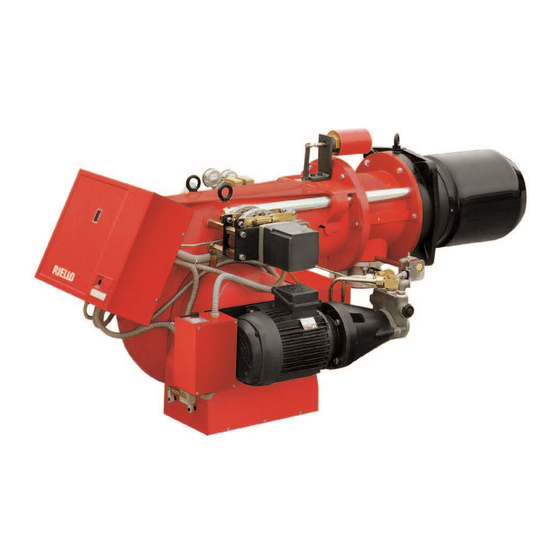
Installation, use and maintenance instructions
Dual fuel heavy oil/ gas burners
GB
Two stage progressive or modulating operation
CODE
20169213
20169214
20169215
20169216
20169217
MODEL
ENNE/EMME 1400
ENNE/EMME 2000
ENNE/EMME 2000
ENNE/EMME 3000
ENNE/EMME 4500
TYPE
618 M
619 M
619 M
620 M
621 M
20176605 (5) - 12/2021
Advertisement
Table of Contents

Related Manuals for Riello ENNE/EMME 1400


Summary of Contents for Riello ENNE/EMME 1400
- Page 1 Installation, use and maintenance instructions Dual fuel heavy oil/ gas burners Two stage progressive or modulating operation CODE MODEL TYPE 20169213 ENNE/EMME 1400 618 M 20169214 ENNE/EMME 2000 619 M 20169215 ENNE/EMME 2000 619 M 20169216 ENNE/EMME 3000 620 M...
- Page 2 Translation of the original instructions...
-
Page 3: Table Of Contents
Contents Declarations....................................3 Information and general warnings............................4 Information about the instruction manual ........................4 2.1.1 Introduction.................................. 4 2.1.2 General dangers................................4 2.1.3 Other symbols ................................4 2.1.4 Delivery of the system and the instruction manual...................... 5 Guarantee and responsibility............................5 Safety and prevention................................ - Page 4 Contents 5.15.4 Gas pressure ................................25 5.16 Electrical connections ..............................27 5.17 Calibration of the thermal relay ..........................28 5.18 Motor rotation ................................28 Start-up, calibration and operation of the burner ........................29 Notes on safety for the first start-up ...........................29 Adjustments prior to ignition (heavy oil) ........................29 6.2.1 Nozzle ..................................29 6.2.2...
-
Page 5: Declarations
Machine Directive 2014/35/EU Low Voltage Directive 2014/30/EU Electromagnetic Compatibility The quality is guaranteed by a quality and management system certified in accordance with ISO 9001:2015. Legnago, 03.05.2021 Research & Development Director RIELLO S.p.A. - Burner Department Mr. F. Maltempi 20176605... -
Page 6: Information And General Warnings
Information and general warnings Information and general warnings Information about the instruction manual 2.1.1 Introduction WARNING: MOVING PARTS The instruction manual supplied with the burner: This symbol indicates that you must keep limbs is an integral and essential part of the product and must not away from moving mechanical parts;... -
Page 7: Delivery Of The System And The Instruction Manual
Information and general warnings 2.1.4 Delivery of the system and the instruction The system supplier must carefully inform the user about: – the use of the system; manual – any further tests that may be required before activating the When the system is delivered, it is important that: system;... -
Page 8: Safety And Prevention
Safety and prevention Safety and prevention Introduction The burners have been designed and built in compliance with the type and pressure of the fuel, the voltage and frequency of the current regulations and directives, applying the known technical electrical power supply, the minimum and maximum deliveries for safety rules and envisaging all the potential danger situations. -
Page 9: Technical Description Of The Burner
ENNE/EMME 4500 230/50/60 3N/400/50 BASIC DESIGNATION EXTENDED DESIGNATION Models available Designation Voltage Start-up Code ENNE/EMME 1400 3N ~ 230/400V 50 Hz Direct 20169213 ENNE/EMME 2000 3N ~ 230/400V 50 Hz Direct 20169214 ENNE/EMME 2000 3N ~ 230/400V 50 Hz Direct... -
Page 10: Burner Categories - Countries Of Destination
Technical description of the burner Burner categories - Countries of destination Country of destination Gas category SE - FI - AT - GR - DK - ES - GB - IT - IE - PT - IS - CH - NO 2ELL (43.46 ÷... -
Page 11: Electrical Data
(see "Mounting L2** Long head blast tube length the burner on the boiler” on page 17). S7960 Fig. 1 TYPE L2** F2-F3 ENNE/EMME 1400 1090 M 16 ENNE/EMME 2000 1090 M 16 ENNE/EMME 3000 1320... -
Page 12: Firing Rates
Technical description of the burner Firing rates The MAXIMUM OUTPUT is chosen from within the continuous The firing rate value (Fig. 2) has been obtained diagram area (Fig. 2). considering an ambient temperature of 20 °C, an The MINIMUM OUTPUT must not be lower than the minimum atmospheric pressure of 1013 mbar (approx. -
Page 13: Burner Description
Technical description of the burner Burner description 20177686 18-6 Fig. 4 Power modulation unit (only on modulating version) Air pressure switch Gas butterfly control rod Nozzle pin aperture magnet Oil control thermostat High limit thermostat Control box release push-button with lock signal Head drive rod Servomotor 10 Air adjustment cam... -
Page 14: Electrical Panel Description
Technical description of the burner 4.10 Electrical panel description 20181970 Fig. 5 Contactor and thermal relay for fan motor (only for direct start-up) Contactor and thermal relay for pump motor Plug-socket on servomotor cable Resistors contactor Terminal board Relay Time relay Relay Electronic thermostat 10 Control box base... -
Page 15: 4.12 Control Box Rfgo-A22
Technical description of the burner 4.12 Control box RFGO-A22 Important notes To avoid accidents, material or environmental damage, observe the following instructions! The control box is a safety device! Avoid opening ATTENTION or modifying it, or forcing its operation. The Manufacturer cannot assume any responsibility for damage resulting from unauthorised work! ... -
Page 16: 4.13 Servomotor Sqm40
Technical description of the burner 4.13 Servomotor SQM40 ... Important notes To avoid accidents, material or environmental damage, observe the following instructions! Avoid opening, modifying forcing ATTENTION servomotor. All interventions (assembly and installation operations, assistance, etc.) must be carried out by qualified personnel. ... -
Page 17: Installation
Installation Installation Notes on safety for the installation After carefully cleaning all around the area where the burner is to The installation of the burner must be carried out be installed, and arranging for the environment to be illuminated by qualified personnel, as indicated in this manual correctly, proceed with the installation operations. -
Page 18: Operating Position
Pierce the closing plate of the combustion chamber, as in Fig. 10. The position of the threaded holes can be marked using the thermal insulation screen supplied with the burner. Fig. 10 ENNE/EMME 1400 ENNE/EMME 2000 ENNE/EMME 3000 ENNE/EMME 4500 Tab. -
Page 19: Mounting The Burner On The Boiler
Installation Mounting the burner on the boiler secure the tube to the boiler, inserting the insulating Provide an adequate lifting system (Fig. 11). screen 9); Lift the burner by means of the hooks to fix it to the Slide the burner in on pins 5), leaving it open by about 100- boiler without separating it from the combustion 120 mm;... -
Page 20: Air Damper Setting
267 standard. In order to guarantee that emissions do not vary, Select the nozzle, with nominal output slightly higher than the one recommended and/or alternative nozzles specified by Riello in actually required, among the following types: the Instruction and warning booklet should be used. -
Page 21: Relationship Between: Nozzle Type And Delivery-Return Pressure
Installation 5.9.3 Relationship between: nozzle type and delivery-return pressure To set the delivery range within which the nozzle must operate, adjust the maximum and minimum fuel pressure on the nozzle re- turn, according to the diagrams shown. S7968 Delivery pressure 25 bar Flow Delivery pressure... -
Page 22: Combustion Head Adjustment
Installation 5.10 Combustion head adjustment The combustion head moves simultaneously with cam If a larger reduction is required, proceed as follows: 8)(Fig. 19), the variable profile cams and the gas butterfly. Head With the servo-motor at 0°, slacken screws 5) and push ring position can be seen on cylinder 2)(Fig. -
Page 23: Heavy Oil Supply
Installation 5.11 Heavy oil supply Explosion danger due to fuel leaks in the Before starting the burner make sure that the presence of a flammable source. return pipe line is not clogged. Any obstruction Precautions: avoid knocking, attrition, sparks and would cause the pump seals to break. -
Page 24: Hydraulic Operation Diagram
Installation 5.12 Hydraulic operation diagram 5.12.1 Oil pressure switch S7980 Burner halt condition Can be adjusted between 2 and 15 bar; in the event of excessive counter-pressure on the fuel return line, it brings the burner to a halt, (recommended calibration: 5 bar). Fig. -
Page 25: Pump
Installation 5.14 Pump 5.14.1 Technical data Pump TA3C4010-5 TA4C4010-7 NVBHRPDC NVBHRMDC Burner ENNE/EMME ENNE/EMME ENNE/EMME ENNE/EMME 1400 2000 3000 4500 Min. delivery rate at 30 bar pressure (1400) kg/h 1000 1500 Min. delivery rate at 40 bar pressure (2000- 3000-4500) Delivery pressure range 7 - 40 7 - 40... -
Page 26: Gas Supply
Installation 5.15 Gas supply Explosion danger due to fuel leaks in the MBC “threaded” presence of a flammable source. Precautions: avoid knocking, attrition, sparks and heat. Make sure the fuel shut-off valve is closed before performing any operation on the burner. The fuel supply line must be installed by qualified personnel, in compliance with current standards and laws. -
Page 27: 5.15.2 Gas Train
Installation 5.15.2 Gas train 5.15.4 Gas pressure Type-approved in accordance with EN 676 and supplied Tab. J indicates the pressure drops of the combustion head and separately from the burner. gas butterfly valve depending on the burner operating output. 1 p (mbar) 5.15.3 Gas train installation G 20 G 25... - Page 28 Installation The values shown in Tab. J refer to: 20167883 – Natural gas G 20 NCV 9.45 kWh/Sm (8.2 Mcal/Sm – Natural gas G 25 NCV 8.13 kWh/Sm (7.0 Mcal/Sm Column 1 Combustion head pressure drop. Gas pressure measured at test point 2)(Fig. 26), with: •...
-
Page 29: Electrical Connections
Installation 5.16 Electrical connections Notes on safety for the electrical wiring The electrical wiring must be carried out with the electrical supply disconnected. Electrical wiring must be made in accordance with the regulations currently in force in the country of destination and by qualified personnel. -
Page 30: Calibration Of The Thermal Relay
Installation 5.17 Calibration of the thermal relay The thermal relay (Fig. 27) serves to avoid damage to the motor due to an excessive absorption increase or if a phase is missing. D8685 For calibration 2), refer to the table indicated in the electrical layout (electrical wiring by the installer). -
Page 31: Start-Up, Calibration And Operation Of The Burner
Start-up, calibration and operation of the burner Start-up, calibration and operation of the burner Notes on safety for the first start-up The first start-up of the burner must be carried out Check the correct working of the adjustment, by qualified personnel, as indicated in this manual command and safety devices. -
Page 32: Adjustments Prior To Ignition (Gas)
Start-up, calibration and operation of the burner Adjustments prior to ignition (gas) In addition, the following adjustments must also be made: Before starting up the burner, it is good practice to Slowly open the manual valves situated upstream of the gas adjust the gas train so that ignition takes place in train. -
Page 33: Servomotor Adjustment
Start-up, calibration and operation of the burner Servomotor adjustment The servomotor adjusts simultaneously, through driving gears, the output and pressure of the air and the delivery of the fuel in use. It performs a 130° rotation in 45s. After the adjustment made in the factory to its 6 cams to allow an initial ignition. -
Page 34: Pressure Switch Adjustment
Start-up, calibration and operation of the burner Pressure switch adjustment 6.8.1 Air pressure switch The air pressure switch is set after all other adjustments have been made. Begin with the switch at the start of the scale. With the burner operating, increase adjustment pressure by slowly turning the relevant knob clockwise until the burner stops. -
Page 35: Maximum Oil Pressure Switch
Start-up, calibration and operation of the burner 6.8.4 Maximum oil pressure switch The maximum oil pressure switch is calibrated in the factory at 4- 5 bar. If the oil pressure in the return line goes above this value, the pressure switch stops the burner in a lockout. To adjust the pressure switches, use a tool to operate the adjustment screw (Fig. -
Page 36: Spray Temperature Adjustment
Start-up, calibration and operation of the burner Spray temperature adjustment 6.9.1 Electronic adjustment thermostat a “high temperature” alarm output is provided on the burner ter- minal strip. (Factory set is approximately 180°C). By means of information relayed from a PT 100 probe immersed in the oil in the delivery manifold, the thermostat adjusts spray Adjustment thermostat probe temperature. -
Page 37: Burner Operation
Start-up, calibration and operation of the burner 6.10 Burner operation 20177684 Normal Lock for start-up failure Control system Pump motor Fan motor Transformer (*) Pre-wash valve Start-up valve Flame Lock-out Fig. 40 (*) oil only (**) Adjusted by timer 6) for oil (6s for gas operations) MOTOR LOCK: this is brought about by the overload cut-out thermal relay when a phase is missing. -
Page 38: Final Checks (With Burner Operating)
Start-up, calibration and operation of the burner 6.11 Final checks (with burner operating) Open the thermostat/pressure switch TL The burner must stop Open the thermostat/pressure switch TS Turn the knob of the gas maximum pressure switch to the ... -
Page 39: Maintenance
Maintenance Maintenance Notes on safety for the maintenance The periodic maintenance is essential for the good operation, Before carrying out any maintenance, cleaning or checking safety, yield and duration of the burner. operations: It allows you to reduce consumption and polluting emissions and to keep the product in a reliable state over time. -
Page 40: Safety Components
Maintenance Burner 7.2.4 Safety components Check that there is no excess wear or loosen screws, especially The safety components should be replaced at the end of their life on cams III (Fig. 30 on page 31). cycle indicated in the following table. Clean the outside of the burner. - Page 41 Maintenance HEAVY OIL OPERATION GAS OPERATION Pump Gas leaks The delivery pressure must comply with the graph on page 18. Make sure that there are no gas leaks on the pipe between the The depression must be less than 0.45 bar. gas meter and the burner.
-
Page 42: Opening The Burner
Maintenance Opening the burner Disconnect the electrical supply from the burner Wait for the components in contact with heat by means of the system main switch. sources to cool down completely. DANGER Close the fuel shut-off valve. DANGER Closing the burner After carrying out maintenance, cleaning or checking operations, reassemble the cover and all the safety and protection devices of the burner. -
Page 43: Led Indicator And Special Function
LED indicator and special function LED indicator and special function Description of LED lamps It turns on when the fan motor is powered (T6) and blinks when RUN/CHECK switch is set to “CHECK” during damper movement phases, PTFI AND MTFI. S9740 It blinks when the air damper is moving towards the maximum opening position until the Damper... -
Page 44: Led Lamps: Burner Operating Status
LED indicator and special function LED lamps: burner operating status OPERATING STATUSES INDICATED BY LEDS DURING NORMAL OPERATION AND CHECK MODE Operation Damper Damper Modulation Ignition Flame Status LED ● = ON open closed Icon S9740 S9741 S9742 S9743 S9744 S9745 S9746 Power OFF/ON... -
Page 45: Problems - Causes - Remedies Signalled By Led Indicators
Problems - Causes - Remedies signalled by LED indicators Problems - Causes - Remedies signalled by LED indicators When an emergency stop occurs, the control device LEDs Thermal unit’s operation, maintenance and indicate the cause of the stop. troubleshooting interventions must be carried out The terminal T3 is not powered. - Page 46 Problems - Causes - Remedies signalled by LED indicators Error / RFGO LED lock-out codes Faults LED 1 LED 2 LED 3 LED 4 LED 5 LED 6 LED 7 Operation Open Closed Auto Ignition Flame Status LED ● = ON damper damper Icon...
- Page 47 Problems - Causes - Remedies signalled by LED indicators Faults LED 1 LED 2 LED 3 LED 4 LED 5 LED 6 LED 7 Off-specification mains voltage ● ● ● ● ● UV: Internal fault ● ● Supervisor processor fault ●...
- Page 48 Problems - Causes - Remedies signalled by LED indicators Fault explanation Faults Cause Solution Post-diagnostics fault Initial power diagnostics fault Check T12, T13 and T14 Make sure that the status of inlets and outlets is correct upon ignition Local reset The user started the manual reset or the Check T21 inlet or reset for normal reset switch is faulty...
- Page 49 Problems - Causes - Remedies signalled by LED indicators Faults Cause Solution Not used Internal processor timeout Internal fault Replace the control device Internal processor timeout Internal fault Replace the control device Combustion air check timeout The system could not perform verification Check the wiring or the air pressure switch tests of the combustion air during the burner sequence...
-
Page 50: A Appendix - Accessories
Pressure 0...16 bar 3010214 RWF55.5 20101965 4...20 mA 0...25 bar 3090873 Potentiometer kit Burner Code ENNE/EMME 1400 - 2000 20074487 ENNE/EMME 3000 - 4500 Spacer kit Thickness Burner Code (mm) ENNE/EMME 1400 - 2000 3000722 ENNE/EMME 3000 - 4500 3000751... - Page 51 Appendix - Accessories Thermal relay kit Bruciatore Code ENNE/EMME 3000 20163347 Gas trains in compliance with EN 676 Please refer to manual. The installer is responsible for the addition of any safety device not foreseen in this manual. ATTENTION 20176605...
-
Page 52: Appendix - Electrical Panel Layout
Appendix - Electrical panel layout Appendix - Electrical panel layout Index of layouts Indication of references Functional layout Functional layout RFGO-A22 Functional layout RFGO-A22 Functional layout RFGO-A22 Functional layout RFGO-A22 Electrical wiring that is the responsibility of the installer Electrical wiring that is the responsibility of the installer Electrical wiring that is the responsibility of the installer Electrical wiring kit RWF50 external Indication of references... - Page 53 Appendix - Electrical panel layout 20176605...
- Page 54 Appendix - Electrical panel layout 20176605...
- Page 55 Appendix - Electrical panel layout 20176605...
- Page 56 Appendix - Electrical panel layout 20176605...
- Page 57 Appendix - Electrical panel layout & 20176605...
- Page 58 Appendix - Electrical panel layout & 20176605...
- Page 59 Appendix - Electrical panel layout 20176605...
- Page 60 Appendix - Electrical panel layout 20176605...
- Page 61 Appendix - Electrical panel layout 20176605...
- Page 62 Appendix - Electrical panel layout " & 20176605...
- Page 63 Appendix - Electrical panel layout 20176605...
- Page 64 Appendix - Electrical panel layout 20176605...
- Page 65 Appendix - Electrical panel layout 20176605...
- Page 66 Appendix - Electrical panel layout 20176605...
- Page 67 Appendix - Electrical panel layout 20176605...
- Page 68 Appendix - Electrical panel layout 20176605...
- Page 69 Appendix - Electrical panel layout 20176605...
- Page 70 Appendix - Electrical panel layout 20176605...
- Page 71 Appendix - Electrical panel layout 20176605...
- Page 72 Appendix - Electrical panel layout 20176605...
- Page 73 Appendix - Electrical panel layout 20176605...
- Page 74 Appendix - Electrical panel layout 20176605...
- Page 75 Appendix - Electrical panel layout 20176605...
- Page 76 Appendix - Electrical panel layout 20176605...
- Page 77 Appendix - Electrical panel layout 20176605...
- Page 78 Appendix - Electrical panel layout 20176605...
- Page 79 Appendix - Electrical panel layout Wiring layout key Electrical control box Servomotor Oil high temperature alarm Ignition transformer Electronic thermostat RWF50 output power regulator Current input DC 4...20mA Limit thermostat/pressure switch Current input DC 4...20mA for remote setpoint change Maximum thermostat Pressure probe Minimum thermostat Pressure probe...
- Page 80 RIELLO S.p.A. I-37045 Legnago (VR) Tel.: +39.0442.630111 http:// www.riello.it http:// www.riello.com Subject to modifications...