
Related Manuals for Riello GI/EMME 600


Summary of Contents for Riello GI/EMME 600
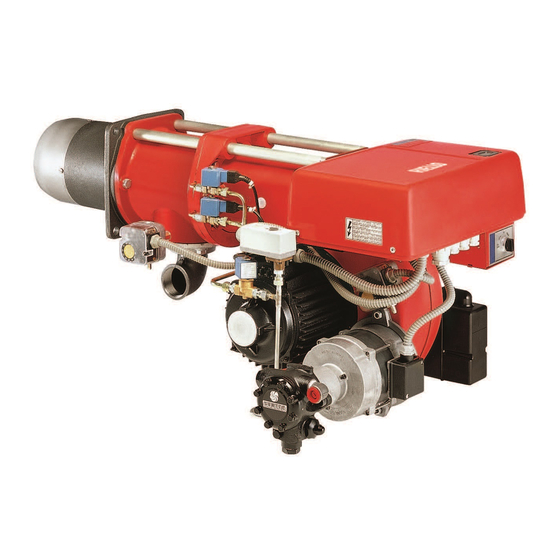
- Page 1 Installation, use and maintenance instructions Dual fuel Gas-Oil/Gas burner MODEL TYPE GI/EMME 600 497 T80 2915144 (6)
-
Page 3: Technical Features
TECHNICAL FEATURES Thermal power 174/348 ÷ 697 kW - 150.000/300.000 ÷ 600.000 kcal/h Fuels Oil, max. viscosity at 20°C: 6mm /s (1.5°E) natural gas with Pci 8600 kcal/m Lpg with Pci 22.200 kcal/m Minimum gas pressure Maximum capacity requires 13 mbar with natural gas, (measured at the test-point) 15 mbar with LPG. -
Page 4: Working Range
DIMENSIONS Boiler front-plate Burner drilling Rp 1 S7564 S7565 D1785 * Extension that you can obtain with special extended head (to be requested separately). WORKING RANGE PRESSURE IN THE COMBUSTION CHAMBER - 2 STAGE OUTPUT Min output at 1 stage 174 kW - 15 Kg/h S7596 Kcal/h MINIMUM GAS PRESSURE - 2... -
Page 5: Gas Supply Line
FIXING TO THE BOILER S7539 In order to devide the combustion head from the rest of the burner, you have to: - remove the connection (1) from the two valves; - remove the 4 screws (2 - 3); - slide the burner body (A) along the rails (4); - mount the group (B) to the boiler’s plate (6) interposing gasket (5). -
Page 6: Oil Supply
OIL SUPPLY Øi 8 Øi 10 S7541 Øi 10 Øi 12 S7542 Please note: all oil lines must be airtight. We suggest copper-piping. Level as the suction pipe, then a none return valve is not required and the section-pipe can be disconnected with- out causing any problems. - Page 7 BURNER ELECTRICAL WIRING (carried out in the factory) KEY TO LAY-OUT S7598 Pump motor capacitor CMV: Contact-maker Selector switch SELECTOR SWITCH MB: Burner terminal strip Pump motor OIL O GAS Fan motor Air pressure switch 3 - 4 Thermal relay 5 - 6 Servo-motor 7 - 8...
- Page 8 ELECTRICAL CONNECTIONS TO THE WIRING TERMINAL BLOCK (to be carried out by the installer) S599 KEY TO LAYOUT MB - Burner terminal strip V1 - 1° stage gas shut off valve MR - Gas train terminal strip V2 - 2° stage gas shut off valve TS - Safety remote control system VS - Gas safety shut off valve TL - Limit control system...
- Page 9 FIXING OF THE ELECTRICAL WIRES All the electrical wires, which are to be connected into the terminal rail 10 (fig. 1) should pass through the cable glands hubes 12 (fig. 1), accordingly the scheme below. S7600 1 - Supply : gland Pg 21 2 - Regulation thermostat : gland Pg 13.5 3 - Safety thermostat...
-
Page 10: Combustion Head Adjustment
COMBUSTION HEAD ADJUSTMENT Adjustments can be made to the burner, when it is still open for installation (see page 3, fixing to the boiler). NOZZLE’S CHOICE Nozzle Spray angle: - usually, 60° 1° 2° 1°+2° - for narrow combustion chambers: 45° kg/h kg/h kg/h... - Page 11 Loosen the two screws (1), move the elbow (2) so that the rear part (3) coincides to the desired set- point (4). Tighten the screws (1). Kcal/h 600.000 540.000 480.000 420.000 360.000 300.000 S7601 S7548 ADJUSTMENT OF THE AIR DAMPER MOTOR STOP - Blue lever S7570 This lever leaves the factory vertically positioned and...
- Page 12 BURNER START-UP CYCLE Venting the gas supply. This is done by removing the screw from the gas pressure switch, or the pressure test point. Screw Pressure gauge fixing point Pressure switch S7577 AIR PRESSURE SWITCH (17 Fig.1) Adjust the air pressure switch after adjustment of all the other parts of the burner, with air pressure switch setted at beginning of the scale.
- Page 13 CURRENT TO THE UV PHOTOCELL Min. value for a good work: 15 µA. If the value is lower, it can depends on: - worked out photocell. - low current (lower than 187V) - bad regulation of the burner. In order to measure the current, use a microammeter of 100 µA c.c., connected to the photocell, as in the scheme, with a capacitor of 100 µF - 10V c.c.
- Page 14 BURNER STARTING DIFFICULTIES AND THEIR CAUSES (GAS) The electrical equipment is fitted with a disk which rotates during the start-up program and can be seen through the release inspection window. When the burner does not start or stops because of a fault, the symbol which appears in the inspection window indicates the type of interruption fault.
- Page 16 RIELLO S.p.A. Via degli Alpini 1 I - 37045 Legnago (VR) Tel.: +39.0442.630111 Fax: +39.0442.630375 Con riserva di modifiche...