Table of Contents
Advertisement
Quick Links
CAUTION
EXTREME CAUTION MUST BE TAKEN WHEN SERVICING THIS MACHINE. EVEN THOUGH
THE MODE SWITCH IS IN THE OFF POSITION, VOLTAGE IS STILL SUPPLIED TO THE EN-
TIRE MACHINE.
WHEN WORKING ON THIS MACHINE MAKE SURE THAT THE POWER CORD IS REMOVED
FROM THE WALL OUTLET.
CHAPTER 1. SPECIFICATIONS .................................................................1 - 1
CHAPTER 2. OPTIONS ...............................................................................2 - 1
CHAPTER 3. SERVICE (SRV) MODE.........................................................3 - 1
CHAPTER 4. HARDWARE DESCRIPTION ................................................4 - 1
CHAPTER 5. TEST FUNCTION ..................................................................5 - 1
CHAPTER 6. DOWN LOAD FUNCTION .....................................................6 - 1
CHAPTER 7. SERVICE PRECAUTION.......................................................7 - 1
CHAPTER 8. IPL (Initial Program Loading) FUNCTION .............................8 - 1
CHAPTER 9. INSTALLATION OF OPTIONS ..............................................9 - 1
CHAPTER 10. CIRCUIT DIAGRAM & PWB LAYOUT ...............................10 - 1
Parts marked with "
" is important for maintaining the safety of the set. Be sure to replace these parts with specified
ones for maintaining the safety and performance of the set.
SERVICE MANUAL
CONTENTS
SHARP CORPORATION
ELECTRONIC
CASH REGISTER
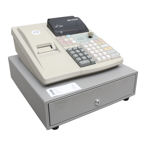
ER-A220
MODEL
(For "V" version)
SRV Key : LKGIM7113RCZZ
PRINTER : LTP-1245
This document has been published to be used
for after sales service only.
The contents are subject to change without notice.
Advertisement
Table of Contents

Related Manuals for Sharp ER-A220


Summary of Contents for Sharp ER-A220
-
Page 1: Table Of Contents
SERVICE MANUAL ELECTRONIC CASH REGISTER ER-A220 MODEL (For "V" version) SRV Key : LKGIM7113RCZZ PRINTER : LTP-1245 CAUTION EXTREME CAUTION MUST BE TAKEN WHEN SERVICING THIS MACHINE. EVEN THOUGH THE MODE SWITCH IS IN THE OFF POSITION, VOLTAGE IS STILL SUPPLIED TO THE EN- TIRE MACHINE. -
Page 2: Chapter 1. Specifications
CHAPTER 1. SPECIFICATIONS 1. Appearance/Rating 1) Rating 3) Key top name Standard Key Top Power source AC local voltage( 10%), 50/60Hz Power consumption Max. 45W, Stand-by : 20W KEY TOP DESCRIPTION 0 to 9,00 Numeric keys Operating temperature 0°C~40°C Decimal point key Operating humidity 10%~90% Clear key... - Page 3 [Functions] Display Description Position Function for each key position Error 8-10 Exx : xx = Error code SRV ’ : System reset PGM Mode SRV : Service mode (SRV/PGM programming) TL/NS : Lights up when a registration is CH, CR finalized by depressing TL/NS, PGM : Allows programming of an item that is not changed fre-...
- Page 4 5. Specifications 6. Drawer: Not standard equipment 1) Drawer box 1) Printer (LTP-1245) No. of station: 1: Receipt or Journal Item Description Model name SK-360 Validation: Size 329(W) x 363(D) x 106(H) Printing system: Line thermal Color Gray 368 No. of dot: 384 dots Material Metal...
-
Page 5: Chapter 2. Options
CHAPTER 2. OPTIONS 1. Options NAME MODEL DESCRIPTION REMOTE DRAWER ER-05DW/06DW KEY TOP KIT ER-11KT7 1 x 1 KYE TOP UNIT ER-12KT7 1 x 2 KYE TOP UNIT ER-22KT7 2 x 2 KYE TOP UNIT ER-11DK7G 1 x 1 DUMMY KYE KIT ER-51DK7G 5 x 1 DUMMY KYE KIT 2. -
Page 6: Chapter 3. Service (Srv) Mode
CHAPTER 3. SERVICE (SRV) MODE CAUTION Before turning the mode switch from the (SRV’) to (SRV), make sure the AC power cord is connected to the wall outlet; otherwise, the data on memory might be destroyed. The SRV key is used for operating in the SRV mode. 1. -
Page 7: Chapter 4. Hardware Description
CHAPTER 4. HARDWARE DESCRIPTION 1. Hard ware block diagram STANDARD DRAWER. POWER SUPPLY OPTION REMOTE DRAWWER ER-05DW/06DW Data bus M30624 Address ROM : 256K Byte RAM : 20K Byte 256K Byte 128K Byte DRIVER , SENSOR REAR 74HC374 Seg. DRIVER PRINTER FRONT LP1245A... - Page 8 +24V : 24V TRANSFORMER LM2574HVM Drawer VLED : 5.7V MC34063 Display VCC : 5V Circuit VDD : 5V HI-MH BATTERY VH : 7.7V MC34063 Printer 2. Description of main LSI’s 2-1. CPU (M30624FGFP) 2) Pin description 1) Pin configuration SYMBOL SIGNAL In/Out Function...
- Page 9 3. Clock generator SYMBOL SIGNAL In/Out Function NAME 1) CPU CLKOUT /RDY Out NOT USE /HOLD /HOLD Controled by P71 12MHz /HLDA Out NOT USE CBCLK Out NOT USE Out Read W42C3103G /BHE Out NOT USE R109 Out Write /CS3 Out Display segment latch XOUT /CS2...
- Page 10 2) RAM control 5. P-OFF circuit Power supply circuit D101 NI-MH battery +24V +24V 1SS353 R128 R121 2.7K 2.4KF R122 R119 13KF A0-A16 A0-A16 A0-A16 IC10A IC10B P-OFF D0-7 D0-7 VREF I/O0-7 BA10393 BA10393 (2.495V) C137 /CS2 R120 R123 0.47uF /CS2 C138 C147...
- Page 11 Equivalent circuit of thermal head 7. Printer control circuit 1) Paper feed motor circuit Heating element 1,2,3,26,27,28 dot 384 dot 1 L-GND 13,14,15,16,17 P-GND LB1843V STB6 STB5 STB4 STB3 STB2 74HC32 74HC123D To Papper feed motor STB1 /LATCH Latch register DATA IN Shift register CLOCK...
- Page 12 8. Paper take up motor drive circuit 10. Buzzer drive circuit VLED D115 MOTOR TA4IN/U BUZ1 TA4OUT/U When the MOTOR signal from the CPU is HIGH, Q1 is turned on to When the BUZ1 signal from the CPU is HIGH, Q6 is turned on to operate the motor.
- Page 13 1) Keyboard 6) RS232/CI signal detection Scan signal : 10 /S0-9 signals Scan signal : 1 /S9 signal Return signal : 6 P92-97 signals Return signal : 1 P91 signal The keys are read by the key matrix following the above signals. The RS232/CI signal is detected by the above signals.
- Page 14 13. SHORT PIN setting The ER-A220 has two SHORT PIN settings. SHORT PIN No. FUNCTION DEFAULT Switching between Normal mode/IPL mode Normal mode Switching RS232C No.9 pin and Cl/+5V Cl signal SP2 : +5V / CI SP1 : Normal mode / IPL mode...
-
Page 15: Chapter 5. Test Function
1) This diagnostic program has been developed for diagnosing ma- #/TM/ST chine functions in the field. The program is contained within the ER-A220. The diagnostic program is stored in the CPU internal Flash mem- 2) Functional description ory which will be executed by the CPU (M30624FGFP) which re-... - Page 16 2) Functional description [3] R/J printer test Key code, MRS switch (not used in ER-A220) state and Cashier code 1) Key operation are displayed. #/TM/ST 2) Functional description Key code Display the following message. MRS switch state (Not used) 1 2 3 4 5 6 7 8 9 0...
- Page 17 117 096 080 064 048 032 a) Check of the display in the test and the content of end print. <ER-A220 STANDARD KEY BOARD LAYOUT> 4) Test termination SUMCHECK DATA = 148 + 132 + 144 + 147 + ········· = 3383...
- Page 18 The error occurrence address is shown in Drawer open sensor not detected. (Drawer closed) hexadecimal at positions shown with The ER-A220 is not provided with the open sensor and thus the [9] CPU internal RAM test letter "C" stays on the display.
- Page 19 2) Functional description BAUD RATE : 9600 BPS Sum check of the external ROM for IPL (40000H - 7FFFFH) is per- Display : formed. If the lower two digits of SUM is 10H, it is normal. 5 0 0 7-SEGMENT DISPLAY: 3) Test termination 3) Check the following items: This check is terminated automatically.
-
Page 20: Chapter 6. Down Load Function
CHAPTER 6. DOWN LOAD FUNCTION 1. General 3. Location of connector pins RAM data can be transmitted in the following two methods. ECR-ECR cable Save the data before servicing as follows: 9PIN D-SUB 9PIN D-SUB Cable : 9 pin D-SUB – 9 pin D-SUB Fig. - Page 21 ECR-ER-02FD cable 4. Application specification The following service (SRV) modes are available for the serial data 25PIN D-SUB 9PIN D-SUB transfer of the ECR ER-02FD 1) Data transmit (Source side) #/TM/ST TL/NS 2) Data receive (Target) #/TM/ST TL/NS 5. Data format A single byte image of the RAM data to be transmitted is divided into a high order 4 bits and low order 4 bits and converted into ASCII code.
- Page 22 Loading data 7. Operational method 1) Turn on the power switch and insert the floppy disk which stores 1) To prepare an ECR to receive data from another ECR or the ER- the data. 02FD, the memory size of the receiving unit must the same as or 2) Start the RECEIVE JOB on the ECR side as follows: greater than the sending unit.
-
Page 23: Chapter 7. Service Precaution
CHAPTER 7. SERVICE PRECAUTION 1. Cautions to be taken when removing 2. Cautions to be taken when installing the upper cabinet the pop-up display connector cable When removing the upper cabinet, first remove the printer cover Exercise care not to have the wrong direction of the pop-up display and then remove the upper cabinet from the let side, as shown in connector cable when connecting the cable to the Key I/F connector the sketch below. -
Page 24: Chapter 8. Ipl (Initial Program Loading) Function
CHAPTER 8. IPL (Initial Program Loading) FUNCTION Power on the ECR. The application program of the ER-A220 is written on the CPU internal FLASH ROM. Enter the Service rest. When servicing the unit, it is necessary to write the application pro- (Turn the Mode switch from SRV’... -
Page 25: Chapter 9. Installation Of Options
Before turning the mode switch from the (SRV’) to (SRV), make sure the AC power cord is connected to the wall outlet; otherwise, the data on memory might be destroyed. 1-1. Outline The ER-A220 allows connection of one remote drawer ER- 05DW/06DW. 1-2. Installation procedure 1) Separating standard drawer Remove the printer cover. - Page 26 2-2. ER-12KT7, ER-22KT7 1) Attach two spacers to the keyboard frame. Key top Guide arm Guide arm 4) Remove the jig under the above condition 3), and press the key top. Yellow White 5) Check that the key top operates properly. 6) Install the key label and the key cap.
- Page 35 5. MAIN PWB LAYOUT (1) Side-A...
- Page 36 (2) Side-B...
- Page 37 6. PRINTER I/F PWB LAYOUT (1) Side-A (2) Side-B 7. KEY I/F PWB 8. CUSTOMER DISPLAY PWB LAYOUT...
-
Page 38: Parts Guide
ER-A220V PARTS GUIDE ER-A220 MODEL PRINTER : LTP1245 SRV key : LKGIM7113BHZZ (for TQ,TS,KA,KB) CONTENTS Exteriors Pop up PWB unit Keyboard unit Printer PWB unit Packing material & Accessories Articles for consumption Drawer box unit(SK360 type) Service options & Service tools... - Page 39 ER-A220V 1 Exteriors PRICE PART PARTS CODE DESCRIPTION RANK MARK RANK 1 G C O V B 2 4 8 8 B H Z Z Printer cover 2 G C A B B 2 5 3 2 B H Z Z Top cabinet 3 X E B S D 3 0 P 1 0 0 0 0 Screw (3´10)
- Page 40 ER-A220V 1 Exteriors R C P 0 0 2 8 8 – 2 –...
- Page 41 ER-A220V 2 Keyboard unit PRICE PART PARTS CODE DESCRIPTION RANK MARK RANK 1 L F R M - 2 3 6 0 B H Z Z Key frame J K N B Z 6 9 0 5 B H Z Z Key top (0) J K N B Z 6 9 0 8 B H Z Z Key top (.)
- Page 42 ER-A220V 2 Keyboard unit 5 0 1 R C P 0 0 2 8 9 3 Packing material & Accessories R C P 0 0 2 9 0 – 4 –...
- Page 43 ER-A220V 4 Drawer box unit(SK360 type) PRICE PART PARTS CODE DESCRIPTION RANK MARK RANK 1 L P L T M 2 3 5 4 B H Z Z Bracket 2 X U B S D 3 0 P 0 8 0 0 0 Screw (3´8) 3 M L E V F 6 6 9 9 B H Z B Bill lever...
- Page 44 ER-A220V 4 Drawer box unit(SK360 type) 5 0 1 5 0 3 5 0 2 R C P 0 0 2 9 1 – 6 –...
- Page 45 ER-A220V 5 Main PWB unit PRICE PART PARTS CODE DESCRIPTION RANK MARK RANK 1 L X - B Z 6 6 4 4 B H Z Z Screw (M3.5´8S) [Q10] 2 P R D A F 2 3 7 4 B H Z Z Heat sink (for KTD998)[Q10] 3 P R D A F 6 6 5 6 B H Z Z...
- Page 46 ER-A220V 5 Main PWB unit PRICE PART PARTS CODE DESCRIPTION RANK MARK RANK Resistor (1/4W 1W ±5%) V R S - T P 2 E G 1 R 0 J [R136,137,141] Resistor (1/4W 1W ±5%) V R S - T P 2 E G 1 R 0 J [R50] Resistor (1/4W 150W ±5%) 72 V R S - T S 2 E P 1 5 1 J...
- Page 47 ER-A220V 6 Key i/f PWB unit PRICE PART PARTS CODE DESCRIPTION RANK MARK RANK Resistor (1/4W 12KW ±5%) V R D - R C 2 E Y 1 2 3 J [R134,135,136,137,138,139,140,141] Resistor (1/4W 12KW ±5%) V R D - R C 2 E Y 1 2 3 J [R142,143] Resistor (1/4W 30W ±5%) 14 V R D - R C 2 E Y 3 0 0 J...
- Page 48 ER-A220V ■ Index PRICE PART PARTS CODE RANK MARK RANK LKGIM7331BHZZ 4- 23 PRICE PART PARTS CODE RANK MARK RANK LKGIW0001BHZZ 2- 14 LKGIW7330BHZZ 4- 22 CCABM2534BH01 4- 11 LPIN-2323BHZZ 4- 26 CCASP2326BH01 LPLTM2353BHZZ 4-501 4- 36 CDRW-2317BH01 4-504 LPLTM2354BHZZ CDRW-2317BH02 4- 15 LPLTM2355BHZZ...
- Page 49 ER-A220V PRICE PART PRICE PART PARTS CODE PARTS CODE RANK MARK RANK RANK MARK RANK RCILC2417BHZZ 5- 20 VHIMC74HC123F 5- 64 RCILC6653BHZZ VHISN74HC138N 5- 21 6- 10 RCILZ1003BHZZ VHISN74HC32DR 5- 22 5- 65 RCORF2031SCZZ 1- 49 VHISN74HC374D 5- 66 RCORF5010BCZZ VHIW42C3103G/ 1- 57 5- 67...
- Page 50 ER-A220V PRICE PART PRICE PART PARTS CODE PARTS CODE RANK MARK RANK RANK MARK RANK XUBSD30P08000 XUBSD40P10000 1- 41 – 12 –...
- Page 51 COPYRIGHT 1999 BY SHARP CORPORATION All rights reserved. Printed in Japan. No part of this publication may be reproduced, stored in a retrieval system, or transmitted. In any form or by any means, electronic, mechanical, photocopying, recording, or otherwise, without prior written permission of the publisher.