
Related Manuals for Extron electronics XTP R HWP 201


Summary of Contents for Extron electronics XTP R HWP 201
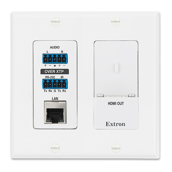
- Page 1 User Guide XTP Extender XTP R HWP 201 XTP Receiver – Decora Wallplate ® 68-2339-01 Rev. A 04 14...
- Page 2 Safety Instructions Safety Instructions • English Инструкция по технике безопасности • Русский WARNING: This symbol, , when used on the product, is intended to ПРЕДУПРЕЖДЕНИЕ: Данный символ, , если указан alert the user of the presence of uninsulated dangerous voltage within the на...
- Page 3 “Extron Safety and Regulatory Compliance Guide” on the Extron website. Copyright © 2014 Extron Electronics. All rights reserved. Trademarks All trademarks mentioned in this guide are the properties of their respective owners. The following registered trademarks , registered service marks...
- Page 4 Conventions Used in this Guide Notifications The following notifications are used in this guide: A warning indicates a situation that has the potential to result in death or WARNING: severe injury. CAUTION: A caution indicates a situation that may result in minor injury. ATTENTION: Attention indicates a situation that may damage or destroy the product or associated equipment.
-
Page 5: Table Of Contents
Installing a UL Listed Metal Junction Box ..7 Audio Configuration Commands ....22 Rear and Side Panel Connectors ......8 Advanced Configuration Commands .... 23 Mounting the XTP R HWP 201 ......9 Front Panel Connectors ........10 XTP System Configuration Software ... 24 Making Connections ......... - Page 6 XTP R HWP 201 Wallplate Receiver • Contents...
-
Page 7: Introduction
XTP matrix switcher (see Power Connection on page 14). To configure and control the XTP R HWP 201, connect a host device, such as a computer, through the USB Config port and enter Simple Instruction Set (SIS) commands (see Configuration and Control... -
Page 8: Key Features
XTP compatibility — Provides high reliability and maximum performance on an economical and easily installed cable infrastructure. The XTP R HWP 201 receives video with embedded audio, bidirectional RS-232 and IR, and Ethernet up to 330 feet (100 meters) over a single shielded twisted pair cable infrastructure. - Page 9 HDMI audio de-embedding — Supports digital HDMI audio de-embedding as a balanced or unbalanced analog stereo signal on a captive screw connector. Remote power capability — To simplify integration, the XTP R HWP 201 can be powered by an XTP CrossPoint Matrix Switcher or XTP Power Injectors.
-
Page 10: Installation
• Making Connections Installation Overview The XTP R HWP 201 can be installed into the provided mud ring or a UL Listed metal electrical junction box. NOTE: If using a junction box, use a metal one only. Prepare the mounting surface. -
Page 11: Installing The Metal Junction Box Or Mud Ring
Route and connect cables to the rear and side panel connectors (see Panel Connectors on page 8). Mount the XTP R HWP 201 to the mud ring or metal junction box (see Mounting the XTP R HWP 201 on page 9). -
Page 12: Installing The Mud Ring
NOTE: The backing clip can be installed as shown in Figure A or Figure B (see figure 3). Use a cross-head (Phillips) screwdriver to fasten the screws and backing clips in place. XTP R HWP 201 Wallplate Receiver • Installation... -
Page 13: Installing A Ul Listed Metal Junction Box
être réduit jusqu’à ce que le câble sorte de la cosse de câble. Le blindage tressé et le blindage en aluminium devraient être connectés à la masse d’un équipement à l’autre bout du câble. XTP R HWP 201 Wallplate Receiver • Installation... -
Page 14: Rear And Side Panel Connectors
Rear Panel Connectors XTP input connector — Connect a twisted pair cable to the RJ-45 connector labeled “XTP IN” on the XTP R HWP 201 and the XTP output port on another XTP device to pass all signals (see TP Cable Termination and Recommendations on page 12). -
Page 15: Mounting The Xtp R Hwp 201
Figure 7. Installing the XTP R HWP 201 in a Metal Junction Box Align the mounting screws on the XTP R HWP 201 with the available holes on the mud ring (see figure 6, ) or metal junction box (see figure 7,... -
Page 16: Front Panel Connectors
(see figure 9 for wiring details). No Ground Here Ring Sleeves Sleeves Do not tin the wires! Ring No Ground Here Balanced Audio Output Unbalanced Audio Output Figure 9. Audio Output Wiring XTP R HWP 201 Wallplate Receiver • Installation... -
Page 17: Making Connections
D I O sécurisés. Ne pas trop serrer. - 2 3 Use pliers or similar tools to tighten the tie L A N wrap, then remove any excess length ( S IG D IO XTP R HWP 201 Wallplate Receiver • Installation... -
Page 18: Tp Cable Termination And Recommendations
Connector Figure 10. TP Cable Termination Supported cables The XTP R HWP 201 is compatible with shielded twisted pair (F/UTP, SF/UTP, and S/FTP) and unshielded twisted pair (U/UTP) cable. ATTENTION: • Do not use Extron UTP23SF-4 Enhanced Skew-Free AV UTP cable or STP201 cable to link the XTP products. -
Page 19: Rs-232 And Ir Over Xtp Communication
Any shorter and the wires can be easily pulled out even if tightly fastened by the captive screws. • S’ils sont un peu plus courts, ils pourraient sortir, même s’ils sont attachés par les vis captives. XTP R HWP 201 Wallplate Receiver • Installation... -
Page 20: Power Connection
Output Cord Figure 12. Power Wiring The XTP R HWP 201 can be connected to a local power supply. WARNING: Electric shock hazard. The two power cord wires must be kept separate while the power supply is plugged in. Remove power before wiring. - Page 21 La longueur idéale est de 5 mm (3/16 inches). TIP: Do not tin the stripped power supply leads. Tinned wires are not as secure in the captive screw connectors and could be pulled out. XTP R HWP 201 Wallplate Receiver • Installation...
- Page 22 Remote power The XTP R HWP 201 can be powered remotely through an XTP Power Injector or through an XTP matrix switcher. ATTENTION: XTP remote power is intended for indoor use only. No part of the network that uses XTP remote power should be routed outdoors.
-
Page 23: Operation
Figure 14. Front Panel Features HDMI Audio Switch The XTP R HWP 201 has an HDMI audio switch (see figure 14, ) that mutes or enables the embedded audio on the HDMI output connector. If necessary, remove the wallplate to access the switch. -
Page 24: Audio Output Overview
1 reset by NOT operate the firmware mistake, cycle power to the version that results from this device to return the firmware mode reset. version running prior to the reset. XTP R HWP 201 Wallplate Receiver • Operation... -
Page 25: Side Panel Indicators
Power LED indicator — Lights when power is applied to the device. Signal LED indicator — Lights when an active XTP video signal is received. Audio LED indicator — Lights when embedded audio output is enabled. XTP R HWP 201 Wallplate Receiver • Operation... -
Page 26: Sis Configuration And Control
Error Responses When the XTP R HWP 201 receives an SIS command and determines that it is valid, it performs the command and sends the corresponding response to the host device. If the command is determined invalid or contains invalid parameters, the receiver returns an error response to the host. -
Page 27: Using The Command And Response Tables For Sis Commands
= Carriage return with no line feed = Pipe (can be used interchangeably with the character). = Space • = Escape key = Can be used interchangeably with the character. XTP R HWP 201 Wallplate Receiver • SIS Configuration and Control... -
Page 28: Command And Response Tables For Sis Commands
= Audio mute = unmute all audio outputs (default) = mute the HDMI audio output = mute the analog audio output = mute the HDMI and analog audio output XTP R HWP 201 Wallplate Receiver • SIS Configuration and Control... -
Page 29: Advanced Configuration Commands
= video or TMDS not detected = video or TMDS detected = HDCP status = No sink device detected = sink detected with no HDCP encryption = sink detected with HDCP encryption XTP R HWP 201 Wallplate Receiver • SIS Configuration and Control... -
Page 30: Xtp System Configuration Software
Configuration Software This section contains installation and configuration procedures for the XTP System Configuration Software for configuring and controlling the XTP R HWP 201. It can also be controlled with SIS commands (see SIS Configuration and Control on page 20). Topics in... -
Page 31: Using The Xtp System Configuration Software
Using the XTP System Configuration Software The XTP R HWP 201 can be controlled directly from the front panel Config port or remotely from an XTP matrix switcher. Connections The XTP System Configuration Software opens to the Connections screen. This screen... -
Page 32: Top Menu
To access this menu, click the Tools menu. Tools Figure 20. Tools Menu NOTE: The options are not Backup and Restore Software Preference available when directly connected to the XTP R HWP 201. XTP R HWP 201 Wallplate Receiver • XTP System Configuration Software... - Page 33 Select file from computer connected host device. The Browse dialog box opens. Select the desired firmware file and click the button. Open Click the button after the firmware finishes updating. Close XTP R HWP 201 Wallplate Receiver • XTP System Configuration Software...
- Page 34 This option opens the XTP System Configuration Software help file in a Web browser. From the menu, select Help Help Extron Website This option opens the Extron website in a Web browser. From the menu, select Help Extron Website XTP R HWP 201 Wallplate Receiver • XTP System Configuration Software...
-
Page 35: Device Settings
NOTE: 0 dB = 100% volume and -64 dB = 0% volume. If a display is connected through a DVI connection, click the check box below the Analog Audio Volume slider to output analog audio. XTP R HWP 201 Wallplate Receiver • XTP System Configuration Software... - Page 36 XTP R HWP 201. Analog Audio — Displays the mute status of the analog audio output. Analog Audio Volume — Displays the analog audio output volume level in a percentage. XTP R HWP 201 Wallplate Receiver • XTP System Configuration Software...
-
Page 37: Reference Information
• Mounting Template Updating Firmware with Firmware Loader To upload and update firmware for the XTP R HWP 201, download the new firmware to a connected computer and upload the firmware with the Firmware Loader utility. Downloading Extron Firmware Loader Figure 26. -
Page 38: Installing Firmware Loader
Once Firmware Loader has been downloaded, run the .exe file from the location where the file was saved. The installation wizard window opens. Follow the instructions on the Installation Wizard screens to install Firmware Loader on the computer. XTP R HWP 201 Wallplate Receiver • Reference Information... -
Page 39: Downloading Firmware
The file can be downloaded from the same page as the firmware. Click the link to the right of the desired device. Download Submit any required information to start the download. Note where the file is saved. XTP R HWP 201 Wallplate Receiver • Reference Information... -
Page 40: Installing Firmware With Firmware Loader
Click the button to start the upload process. Begin Close Firmware Loader when the field shows , the Remaining Time 00.00.00 column is , and the field is Progress 100% Status completed XTP R HWP 201 Wallplate Receiver • Reference Information... -
Page 41: Mounting Template
CUT-OUT AREA FOR WALL MOUNT Top Panel Figure 30. Mounting Template for 2-gang Mud Rings (Not to Full Scale) Please measure the printed template before cutting. NOTE: Measure the template before cutting. XTP R HWP 201 Wallplate Receiver • Reference Information... - Page 42 Extron Electronics makes no further warranties either expressed or implied with respect to the product and its quality, performance, merchantability, or fitness for any particular use. In no event will Extron Electronics be liable for direct, indirect, or consequential damages resulting from any defect in this product even if Extron Electronics has been advised of such damage.