Table of Contents
Advertisement
Quick Links
Optical Measuring Instrument
USPM-RUIII series
USPM3-100、USPM3-200
Hardware Operation Manual
Before you get started
Thank you for purchasing Olympus Lens Spectral Reflectivity Measurement
USPM3-100/USPM3-200. Before you start using it, please be sure to read this operation
manual carefully, and then, store it in a readily accessible safe place, so that it can be
referred to at any time you need it. Our warranty card is attached to the back of the
manual. Complete the required entries, and then store the card in a safe place.
PV6088-F4E017
1
Advertisement
Chapters
Table of Contents

Related Manuals for Olympus USPM-RUIII Series


Summary of Contents for Olympus USPM-RUIII Series
- Page 1 Hardware Operation Manual Before you get started Thank you for purchasing Olympus Lens Spectral Reflectivity Measurement USPM3-100/USPM3-200. Before you start using it, please be sure to read this operation manual carefully, and then, store it in a readily accessible safe place, so that it can be referred to at any time you need it.
- Page 2 About the personal computer (hereinafter "computer") We (Olympus) will take no responsibility for any and all damage arising out of the use or malfunction of the unit, including, but not limited to, any damage to the data stored in your personal computer(s).
- Page 3 SAFETY PRECAUTIONS About safety If this product is used in a way that is not described in this document, safety is not guaranteed, in addition to the risk of failure. Always adhere to the instructions given here. Description of Symbols and Terms Used in This Instruction Manual The following symbols and terms are introduced in connection with possibly hazardous operations and practices according to the importance of the involved hazards.
- Page 4 Symbols relating to safety Lens Spectral Reflectivity Measurement USPM3-100/USPM3-200 contains the following symbols. Handle the product safely, keeping in mind the significance of these marks. Symbols Description Avoid touching the surface since it is hot. There is a risk of burns. Indicates an unspecified, common danger.
- Page 5 If the following cautions are not observed, there may be a possibility of fire, electric shock, etc., which could result in serious injury to the user or death. Do not install the device in a location that is frequently exposed to dust, moisture, oily fumes, or steam.
- Page 6 Do not touch on the light source. Moreover, do not put the thing. The light source (U-LH100L-3) becomes very hot while the lamp is on. Do not touch on the light source. Moreover, do not put the thing. It may lead to the burn and a fire.
- Page 7 Always use the supplied power cord. Employing any other cables than those supplied may cause failures due to internal and/or external noises. The supplied cables are not usable with any other devices. When no power cord is attached to the product, refer to the “Precautions for proper use of the power cord”...
- Page 8 Exert good caution in focusing! When bringing the reflection sample surface into focus, use good caution not to allow the objective to inadvertently hit the sample surface. Measure the sample at a normal temperature If the sample temperature is higher than normal, the sample may transform or give damaged to the stage..
- Page 9 Position of the warning label Warning labels The lamp house, which becomes hot, has a warning label (back of the unit). Make sure to adhere to the instructions. If the label is missing, or it gets dirty or starts to peel, contact your supplier for a replacement. Warning label Indicates precautions about replacement of lamps.
-
Page 10: Table Of Contents
TABLE OF CONTENTS PURPOSES AND FEATURES ····························· 11 CARRYING AND INSTALLATION ························· 12 NAMES AND FUNCTIONS OF COMPONENT PARTS ···························································· 15 ASSEMBLING AND CABLING ····························· 22 MEASURING METHOD ····································· 25 PRINCIPLE OF MEASUREMENT ························· 28 REPLACEMENT OF FUSES ································ 29 REPLACEMENT OF LAMP ································... -
Page 11: Purposes And Features
1. PURPOSES AND FEATURES The product is intended to measure spectral characteristics, including reflectance. Do not use for any other purpose. 1.1 Intended uses of this product Lens Spectral Reflectivity Measurement USPM3-100/USPM3-200 is intended to measure the reflectance of a coated plane. Through easy operations, the reflectance of a subject is calculated in comparison to that of the reference sample. -
Page 12: Carrying And Installation
2. CARRYING AND INSTALLATION Input voltage is configured to 100–120 V or 220–240 V, depending on the shipment destination. There is a label indicating the voltage setting on the back surface. Use this product within the voltage range. Otherwise there is a risk of damage or fire. Make sure to contact our service department when you move it into a place having a different voltage range. - Page 13 2.2. How to carry and install the product Keep the following cautions in mind when installing the product: Always firmly hold the base when carrying or installing the product. Otherwise there is a risk of failure. Base Always use two or more persons to unpack, install or carry the device, which weighs about 20 kg.
- Page 14 2.3. How to clean Use a commercial air blaster to blow dust off the lens and then wipe it softly with a sheet of lens cleaning tissue (or washed gauze). Wipe off any fingerprints or oils with a sheet of lens cleaning tissue dampened with a little absolute alcohol.
-
Page 15: Names And Functions Of Component
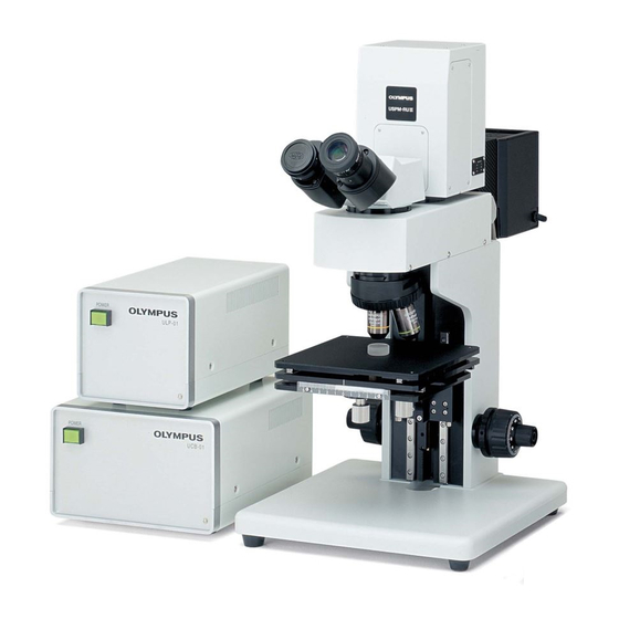
3. NAMES AND FUNCTIONS OF COMPONENT PARTS 3.1. Names of Component Parts (2) Ocular body tube (3) Photometric head (7) Computer (4) Lamp house (1) Main unit (5) Control box (6) Light source power supply Figure 1-1. The complete system (10)Eyepiece (9)Objective lens of twenty magnifications (MPLFLN 20×) (8)Objective lens of ten magnifications (MPLFLN 10×) - Page 16 (12) Photometric cable (14) IO cable (13) Main unit cable (11) USB cable Figure 1-3. Cables supplied (16) Calibration sample for wavelength calibration (15) BK7 reference sample Figure 1-4. Samples supplied PV6088-F4E017...
- Page 17 Operation Manual (this document) (17)Lens Spectral Reflectivity Measurement (USPM3-100/USPM3-200) Hardware Operation Manual (18)USPM-RU Software Operation Manual (19)USPM-RU/RUIII Installation Guide (20) High-intensity halogen lamp (21)Installation CD (22)Set of hexagon wrenches Figure 1-5. Accessories in box PV6088-F4E017...
- Page 18 3.2. Features of each component The device Main unit Contains the spectrometric optical system. The ocular body tube (U-BI30-2) Used for observing the reflected light from the subject. Photometric head (USPM-380) Receives and conducts spectrometry of light from the subject. Lamp house (U-LH100L-3) Accommodates a halogen lamp.
- Page 19 Samples (15) BK7 reference sample (reference) Used for setting the reference values. (16) Calibration sample for wavelength calibration (CALIB sample) Used for checking and calibrating the wavelength direction. Accessories (17) Lens Spectral Reflectivity Measurement (USPM3-100/USPM3-200) Hardware Operation Manual The manual describes how to install the product, conduct measurements with it, and perform maintenance.
- Page 20 3.4.Names of the parts of the control box (UCB-01) (1) Power switch (6) IO connector (2) USB connector (5) Power inlet (3) Main unit connector (4) Photometric connector Figure 2. Control box 3.5. Features of the control box (UCB-01) Power switch Turns the control box power on/off.
- Page 21 3.6. Names of items on light source power supply (ULP-01) (2) IO connector (3) Lamp connector (1) Power switch (4) Power inlet Figure 3. Light source power supply 3.7. Features of light source power supply (ULP-01) Power switch Turns the control box power on/off. IO connector Terminal to receive and send the control signals.
-
Page 22: Assembling And Cabling
4. ASSEMBLING AND CABLING Input voltage is configured to 100–120 V or 220–240 V, depending on the shipment destination. There is a label indicating the voltage setting on the back surface. Use this product within the voltage range. Otherwise, there is a risk of damage or fire. Make sure to contact our service department when you move it into a place having a different voltage range. - Page 23 Install the photometric head into the main unit. Fix it with a lateral screw. Size of the fixture screw: M5 Hexagon wrench: 2.5 mm Photometric head Ocular body tube Fixture screw Main unit Connect the lamp cable on the lamp house to the light source power supply. Connect the IO cable to the light source power supply and the control box.
- Page 24 Connect the main unit cable to the main unit and the control box. Connect the main unit cable in the orientation shown in Fig. 6. Figure 6. Orientation of the main unit cable Connect the USB cable to the computer and the control box. Install the lamp into the lamp house.
-
Page 25: Measuring Method
5. MEASURING METHOD When the computer is misbehaving or any failure is found in the measurement data, plug off and reinsert USB cable and then reboot the software. If you still have such troubles after rebooting the software, please turn off the Control Power Supply Box and then reboot the computer. - Page 26 (8) Place the reference sample on the stage, and bring over the objective close to the stage. While looking into eyepiece A, move the stage away gradually to a point where the ring image (Image B) is focused into a pinhole image (Image A). When the focus has been adjusted properly, the profile of a bright pinhole image will come into sight clearly.
- Page 27 (9) When the reference sample is in true focus, press the Reference button to measure its reflectance. (10) Press the Measure 1 to Measure 10 buttons with the reference sample maintained in focus, and the results of reflectance measurement of the object under measurement will be indicated.
-
Page 28: Principle Of Measurement
6. PRINCIPLE OF MEASUREMENT Figure 7 represents an optical diagram of the USPM3-100/USPM3-200. In the diagram, the luminous flux that has irradiated the zonal mask turns into a parallel luminous flux as it passes through the collimator lens, and is reflected from the half mirror to go through the objective. -
Page 29: Replacement Of Fuses
7. REPLACEMENT OF FUSES The fuse is located in a tray at the lower part of the power cord connector on the light source and control box power supplies. Determine which power supply’s fuse needs to be replaced. Always turn off the power and unplug the power cord before removing or installing or a fuse. -
Page 30: Replacement Of Lamp
8. REPLACEMENT OF LAMP To avoid electric shock and burns, always turn off the power switch, unplug the cord, and wait until the lamp is cool to the touch for replacement. Avoid touching the halogen lamp with your finger or smudging it with dirt. -
Page 31: Specifications
9. SPECIFICATIONS Item Specification Approx. 60 μm (When the 10x objective is used) Spot diameter Approx. 30 μm (When the 20x objective is used) Lamp Halogen lamp: 12 V 100 W (7023 from PHILIPS) Stage Size: 180180mm Withstand load: 1 kg Operating range: (X) 80mm, (Y) 85mm, (Z) 85mm Maximum allowable temperature of stage surface is 180ºC Wavelength range... - Page 32 -Computer Computer and monitor CPU: Intel CPU 2.0 GHz or better, PC/AT compatible Chipset: Made by Intel Corporation (recommendation) Memory: 4 GB or greater HDD: more than 40 GB ® Supported OS: Windows 10 Professional (64-bit version) Optical drive: A drive that can read a CD-ROM (external types can also be used.) Interface: USB 2.0 ...
-
Page 33: Laws And Regulations
10. LAWS AND REGULATIONS 10.1. About FCC NOTE: This equipment has been tested and found to comply with the limits for a Class A digital device, pursuant to Part 15 of the FCC Rules. These limits are designed to provide reasonable protection against harmful interference when the equipment is operated in a commercial environment. - Page 34 10.3.About disposal Follow the state and local regulations and ordinances when disposing of the product. 10.4.Chinese RoHS Directive This mark indicates the environmental protection use period applicable to electronic information products sold in China in accordance with the “Management Methods for Controlling Pollution by Electronic Information Products”...
-
Page 35: Quality Assurance (Warranty Sheet)
(1) If a malfunction occurs due to a manufacturing defect within the validity of the warranty period while the product is used properly in accordance with the instruction manual and the caution labels on the main unit, Olympus Corporation will repair the product free of charge. - Page 36 The warranty is not intended to restrict the rights of the customer. Even after the warranty period, the service department at Olympus will gladly welcome any questions. Contact the support division listed in the attachment.
-
Page 37: Appendix
APPENDIX ○ Principle of calculating spectral reflectance How to calculate spectral reflectance with the product is described below. The product measures the strength of spectral reflectance of the reference, whose reflectance is known ( (λ)) and that of the sample to be measured, whose reference reflectance is unknown ( (λ)). - Page 38 Checklist for inspection of the lighting device (lamp house) Read the manuals carefully before performing lamp house inspections. Inspections on a regular basis (at least once every half year and at the time of lamp replacement) is recommended in order to ensure safe use. ...
-
Page 39: Precautions For Proper Use Of The Power Cord
○ Precautions for proper use of the power cord When no power cord is attached to the product, refer to the "Specification" and "Certification codes" below to choose a proper power code for the unit. We do not guarantee the electrical safety of the product, if an incorrect power cord is connected to the product. - Page 40 HAR flexible codes Table 2. Certification organizations and code labels Labels Replacement symbol with (Probably marked on the black-red-yellow line Certification organization cover or insulating part in Length (mm) the internal wiring) Black Yellow Comite Electrotechnique Belge CEVEC <HAR> (CEBEC) Verband Deutscher Elektrotechniker <VDE>...
- Page 41 ******************************************************************************************************** Printed in Japan © 2011 Olympus Corporation. All rights reserved. Unless otherwise stated in this document, no content in whole or in part may be copied or distributed without permission. Company names and product names described in this document are trademarks or registered trademarks of their respective owners.
- Page 42 USPM-RU Ver3.21.004 Software Operation Manual PV6253-F4E016...
- Page 43 PREFACE Before you get started Thank you for purchasing Olympus USPM-RU Ver.3.21. Before you start using it, please be sure to read this operation manual carefully, and then, store it in a readily accessible safe place, so that it can be referred to at any time you need it.
- Page 44 Contents Contents PREFACE ································································· 1 General ······························································· 3 Tutorial (Measuring Procedure) ·································· 4 Main Window ····················································· 10 Menu List ·························································· 15 Details of [File] Menu ··········································· 17 Details of [Display] Menu······································· 20 Details of [Standard] Menu ····································· 27 Details of [Analyze] Menu ······································ 31 Details of [System] Menu ·······································...
-
Page 45: General
1. General 1. General USPM-RU Ver.3.21 is a control software for a spectral reflectivity measurement system with measurement wavelengths ranging from 380nm to 780nm (or, 440nm to 840nm). Since it stores the measuring conditions for different types of measurement objects (i.e., samples), user-set optimum conditions can be set up again instantaneously when the stored file is called up. -
Page 46: Tutorial (Measuring Procedure)
2. Tutorial (Measuring Procedure) 2. Tutorial (Measuring Procedure) 2.1. Hardware starting procedure Failure to follow the procedure may result in abnormal operation. In such a case, turn of the power again. Then start up the program according to the following procedure. Turn on the power of the control box. - Page 47 2. Tutorial (Measuring Procedure) 2.4. Closing procedure for USPM-RU Ver.3.21 (1) Click [File (F)] and select [Quit (X)]. The message "Save changes to the configuration file?" will be displayed. Select and click [Yes], [No], or [Cancel]. You will be returned to the icon screen through which the program was started before.
- Page 48 2. Tutorial (Measuring Procedure) (2) How to find the front spot (How to discriminate between the front spot and the back surface spot.) When the light donuts are laid one over the other concentrically, lower the Z-stage gradually while looking into the right-hand eyepiece, with the lens under measurement brought close to the objective.
- Page 49 2. Tutorial (Measuring Procedure) 2.6. Measuring procedure (1) Perform warming-up for some 15 minutes after turning on the halogen lamp. Place the reference (BK7) supplied in the same package on the stage, and bring the reflection spot into focus while looking into the right-hand eyepiece. (2) Click the [Background] button.
- Page 50 2. Tutorial (Measuring Procedure) 2.7. Selection of measurement data [] button The radio button located to the left of the Measure button is a data selection button. It indicates whether or not data is currently selected. 2.8. Deletion of measured data ...
- Page 51 2. Tutorial (Measuring Procedure) appear. Enter any desired test No., measuring position, measurer's name, coating device No., and measurement date, and then click the [OK] button. Next, the [Save File As] window will be displayed. Select the target directory, key in the file name, and click [Save]. This operation will save the measured spectral reflectance data on the disk.
-
Page 52: Main Window
3. Main Window 3. Main Window 3.1 Main panel 3.2 Chromaticity diagram panel 3.3 Result panel 3.4 Cursor panel 3.6 Status bar 3.5 Buttons 3.1. Main panel After measurement, this panel displays any of the following measured data, according to the settings made through the [Display] menu: Spectral reflectance graph ... - Page 53 3. Main Window 3.2. Chromaticity diagram panel (440nm - 840nm excluded) This panel shows the color information of measurement results at all times. The chromaticity diagram panel is displayed according to the settings of the [Chromaticity diagram] tab of [Display][Graph setting]. The fields (2º, 10º) and light sources (A, B, C, D65) currently specified are indicated at the top of the chromaticity diagram.
- Page 54 3. Main Window 3.2.4. Display button This button displays the accumulated chromaticity diagram data. This chromaticity diagram window has [Clear], [All Clear], [Save], [Load], and [Close] buttons. [Clear] button Deletes data sequentially starting from the newest one. [All Clear] button Deletes all the chromaticity diagram data.
- Page 55 3. Main Window position where the cursor is located are indicated. When refractive index is displayed on the panel, wavelength [nm] and refractive index [n] of the cursor position are indicated. When the quantity of light is displayed on the panel, wavelength [nm] and the value of the quantity of light are indicated. When reflectance text or the chromaticity diagram is displayed on the panel, the cursor panel remains inactive.
- Page 56 3. Main Window 3.6. Status bar The status bar indicates the following items: Date : Indicates the current date of the personal computer. Time : Indicates the current time of the personal computer. Standard judgment result : When standards are specified, this item indicates whether the measured data meets those standards or not.
-
Page 57: Menu List
4. Menu List 4. Menu List 4.1. [File] menu [Open]: Opens a measured data file and loads it to the computer. [Save as]: Saves measured data to a file named arbitrarily. [Open config file]: Opens an configuratioin file and loads it to the computer. ... - Page 58 4. Menu List [Additional Data]: Opens a test information input screen when saving data. 4.3. [Standard] menu [Standard setting]: Used to set standards. 4.4. [Analyze] menu [Film thickness setting]: Used to make settings for a film thickness measurement. ...
-
Page 59: Details Of [File] Menu
5. Details of [File] Menu 5. Details of [File] Menu 5.1. [Open] menu Opens a measured data file and loads it to the computer. The loaded data is displayed on the reflectance panel and chromaticity diagram panel in accordance with the various settings made (Reflectance and refractive index graph indications, or refractive index text indication, etc.). - Page 60 5. Details of [File] Menu Data File(*.dat) This format is equal to previous version software like 1.10 or 2.00. All measured data point is saved. Additional data is not created Data File(5)(*.dat) This format is equal to previous version software like 1.10 or 2.00 .Only 5 measured data points are saved.
- Page 61 5. Details of [File] Menu 5.7. [Print] menu Opens the [Print] window to execute various types of printing. On the [Print] window, selection is made from the graph print, text print, graph+text print, and the number of text steps (1nm/10nm). The graph print outputs a reflectance graph or refractive index graph directly to a printer.
-
Page 62: Details Of [Display] Menu
6. Details of [Display] Menu 6. Details of [Display] Menu [Display] of the Main Menu is selected to make settings related to the indications of USPM-RU. 6.1. [Reflectance graph] menu Displays measured spectral reflectance data in a graph on the reflectance panel. When checked at the start, [Reflectance graph] displays measured data in a graph, with wavelength [nm] on the abscissa, and reflectance [%] on the ordinate. - Page 63 6. Details of [Display] Menu 6.8. [Graph setting] menu The [Graph setting] menu displays the [Graph setting] window, where detailed settings for graphic indications of measured data are made. The settings are grouped by tabs. Make setting by selecting the intended tab. 6.8.1.
- Page 64 6. Details of [Display] Menu [Display wavelength][Full scale] If [Full scale] is currently checked, the maximum indication range from 380 to 780 [nm] will be displayed in a graph, in disregard of the set values of [Min] and [Max]. (Range from 440 to 780 [nm] on a model with 440nm - 840nm).
- Page 65 6. Details of [Display] Menu [Display reflectance][Min] Specify the minimum value for the reflectance scale. The range of this setting is from 0.0 to 100 [%]. [Scale][Automatic Scale] Specify the automatic setup for reflectance graduations. If this is checked, an appropriate spacing of graduations for the scale width of reflectance will automatically be set up.
- Page 66 6. Details of [Display] Menu 6.8.5. [Chromaticity] tab (440nm - 840nm excluded) Make settings for an indication chromaticity diagram. [Display setting][XYZ chromaticity][L*a*b chromaticity] Specify the chromaticity diagram to be displayed on the chromaticity diagram panel. [Standard light source] [A] [B] [C] [D65] Specify the light source to be used in calculating chromaticity coordinates.
- Page 67 6. Details of [Display] Menu 6.9. [Setting list] menu Displays a listing of measurement setup parameters currently specified. [Close] button Closes the [USPM setting list] window. [Print] button Executes printing of the [USPM setting list] window. Make printer setup through [Print Setup] of the [File] menu.
- Page 68 6. Details of [Display] Menu There, the test No., Notes 1, Notes 2, and measurement date can be entered for each one of [DATA1] to [DATA10]. The test No. should be entered in not more than eight characters. When measured data is saved on DAT format, notes1 of data1 is used. ...
-
Page 69: Details Of [Standard] Menu
7. Details of [Standard] Menu 7. Details of [Standard] Menu USPM-RU compares measured data to the preset standard and judges whether the data meets it or not. 7.1. [Standard setting] menu In the [Standard setting] menu, the standard for OK/NG judgment is set up, and the reference values are entered. - Page 70 7. Details of [Standard] Menu decides OK or NG using the luminous reflectance. Key in the upper-limit value and lower-limit value. The result will be indicated as Rv: OK/NG in the status bar. 7.1.2. Chromaticity diagram (440nm - 840nm excluded) When the [Enable] check box in [Judge: Chroma] is checked, the program decides OK or NG using the Chroma C*.
- Page 71 7. Details of [Standard] Menu ● Examples Ex1) Standard setting of reflectance Check enable on reflectance is and enable on condition 1 to 3. Then set the Condition 1 to 3 to next values. wave Condition 1 400 [nm] 4.2 [%] 4.6 [%] Condition 2 500 [nm]...
- Page 72 7. Details of [Standard] Menu Ex2) Standard setting of chromaticity diagram Check enable on chroma and hue . Then set the chroma and hue to next values. Chroma Yellow lines represent reflectance of standard. Blue circle represents measurement data. OK/NG is displayed in the red circle.
-
Page 73: Details Of [Analyze] Menu
8. Details of [Analyze] Menu 8. Details of [Analyze] Menu 8.1. [Film thickness setting] menu Under this menu, the [Film thickness setting] window is displayed, and various types of parameters for monolayer film thickness measurements are set up. 8.1.1. [Measurement] tab Basic parameters for a film thickness measurement are set up. - Page 74 8. Details of [Analyze] Menu * If [Use the board refractive index] is currently selected, the peaks or valleys will be selected automatically. In other cases, valleys will be selected. [Type B] This method calculates a film thickness from the wavelengths of the two peaks or valleys most widely spaced within the measurement wavelength range.
- Page 75 8. Details of [Analyze] Menu [Type B] - [Physical film thickness] : Number of the peaks or valleys detected between inclusive : Physical film thickness [nm] ...
- Page 76 8. Details of [Analyze] Menu 8.1.2. [Dispersion] tab Specify the refractive index of the coat to be used for film thickness calculation. [Setting coating refractive index] [Fixed Value] If [Fixed Value] is currently selected, the refractive index set at the [Fix Value] tab will be employed as that of the coat for film thickness calculation.
- Page 77 8. Details of [Analyze] Menu [Use the board refractive index] If [Use the board refractive index] is currently selected, the file data (Reflectance data of board: *. csv) set at the [board] tab, the wavelengths of the peaks or valleys of coat + board reflectance, and the reflectances at those wavelengths will be employed as the coat refractive index for film thickness calculation.
- Page 78 8. Details of [Analyze] Menu 8.1.4. [Formula1] tab The refractive index of the coating material to be measured is employed in a dispersion equation that uses the parameters of A0 to A5. Equation (9-1), which is used in [System], is employed as the dispersion equation.
- Page 79 8. Details of [Analyze] Menu 8.1.6. [File] tab Specify the file of the refractive index of the coating material. The file will be that of the refractive index of 380 to 780 [nm] in steps of one [nm] in text format. Reference: For details on the file format, see "12.
- Page 80 8. Details of [Analyze] Menu 8.1.8. [Save] button Saves the coat reflectivity currently set in the window to a file. For instance, if a fixed value setting is specified and its value is 1.2 [n], the refractive index data of 1.2 [n] at 380 to 780 [nm] will be saved in the specified file name.
- Page 81 8. Details of [Analyze] Menu film thickness measurements in a graph. This graph is displayed as graph data when the displayed values of film thickness measurement results are pressed with the [Add] button. The data can be added up to a maximum of 50 points. 8.3.1.
- Page 82 8. Details of [Analyze] Menu 8.3.4. [Data information] Indication of [Points] Shows the total number of data present on the graph. The maximum number of data is 50 points. Indication of [Thickness] The measurement unit ("[nm]/"[nd]") is [nm] if physical film thickness was selected at [Unit] of the [Film thickness measurement], or [nd] if optical film thickness was chosen.
- Page 83 8. Details of [Analyze] Menu 8.4. [Color difference] menu Opens the [Color difference measurement] window, calculates and indicates color difference ΔE. Select any two data points and press the [Calculation] button. The result will be displayed. The color difference is calculated by this equation. ...
-
Page 84: Details Of [System] Menu
9. Details of [System] Menu 9. Details of [System] Menu The basic equation for seeking spectral reflectances using the USPM-RU is indicated further below. The spectral reflectance of a sample is calculated with reference to the known reflecting plane of the reference, and based on the spectral reflection intensity of the reference, spectral reflection intensity of the sample, and spectral intensity of the background. - Page 85 9. Details of [System] Menu of fixed values, Schott, Sellmeier, or a file. When the window is closed by pressing [OK] after the setup, the data set here will be applied to the calculation. Note: When a file has been specified, open the file by the [File] tab. 9.1.2.
- Page 86 9. Details of [System] Menu Equation (9-1) ...
- Page 87 9. Details of [System] Menu 9.1.5. [File] tab Specify a file data as the theoretical spectral reflectance of the reference. The file data will be a reflectance in text format in steps of one [nm]. This allows that spectral reflectance data measured with another spectrometer, etc., be used as the theoretical spectral reflectance data of the reference.
- Page 88 9. Details of [System] Menu [Sampling][Sampling time] Specify a sampling time in [mSec]. The range for this setting is from 30 to 10000 [mSec]. Set an appropriate time for each sample, so that the reflectance of the reflecting plane of the reference or that of the sample, whichever is higher, assumes a value on the order of 70% to 80% of the maximum value of 4080.
-
Page 89: Help] Menu
10. [Help] Menu 10. [Help] Menu 10.1. [Version] menu Displays the version. PV6253-F4E016... -
Page 90: About The Calibration Method For Wavelength Direction
11. About the Calibration Method for Wavelength Direction 11. About the Calibration Method for Wavelength Direction 11.1. General description of calibration The calibration of the wavelength direction refers to the setting that is made to display the spectral reflectance data measured with USPM in a correct position by means of a sample whose spectral reflectance peak is known (measured with other calibrator, etc.). - Page 91 11. About the Calibration Method for Wavelength Direction Measurement of sample Bring the calibration sample face that looks blue into focus on the reflecting mirror face, as in the case of the reference, and then, measure the sample. Calibration of wavelength Display the [Calibration] window through the [System][Calibration] menu, and enter [Shift Value].
- Page 92 11. About the Calibration Method for Wavelength Direction PV6253-F4E016...
-
Page 93: File Configuration
12. File Configuration 12. File Configuration USPM-RU uses the following files on the program. 12.1. Startup file (uspm.int) This file is loaded at the time USPM-RU is launched, and is named "uspm.int". This file stores the name of the configuration file which was in use when USPM was last closed. When the stored configuration file is loaded again, the program can be started up in the same environment. - Page 94 12. File Configuration Standard data file(*.std) If the following file names are specified, the program loads those files after the configuration file is loaded. Files in different versions or those with different wavelength regions cannot be loaded. (*: An arbitrary file name) Data file ID tag Main panel indication type Reference data display/non-display...
- Page 95 12. File Configuration Reference file name Sampling time Film thickness measurement-ready flag Measurement type Unit type Dispersion equation type Fixed value Schott's parameter A0 for film thickness Schott's parameter A1 for film thickness Schott's parameter A2 for film thickness Schott's parameter A3 for film thickness Schott's parameter A4 for film thickness Schott's parameter A5 for film thickness Sellmeier's parameter A1 for film thickness...
- Page 96 12. File Configuration The CSV format USPM-RU Ver3.21 Data File : Data file ID tag wave, DATA1, Data2, ... , Data10 : Data name wavelength380, Data1 Measured value at wavelength 380, Data2 Measured value at wavelength 380, --- Data10 Measured value at wavelength 380 wavelength381, Data1 Measured value at wavelength 381, Data2 Measured value at wavelength 381, --- Data10 Measured value at wavelength 381 wavelength382, Data1 Measured value at wavelength 382, Data2 Measured value at wavelength 382,...
- Page 97 12. File Configuration reflectance, sample No., measuring position, measurer, coating device No., and measurement date. USPM-RU Ver3.21 AddData File : Data file ID tag Item name, L* of Data1, L* of Data2, L* of Data3, --- Item name, a* of Data1, a* of Data2, a* of Data3, --- Item name, b* of Data1, b* of Data2, b* of Data3, --- Item name, x of Data1, x of Data2, x of Data3, --- Item name, y of Data1, y of Data2, y of Data3, ---...
- Page 98 12. File Configuration USPM-RU Ver3.21 Reference File : Reference file ID tag 4.43729459935712 : Reflectance data [%] (380[nm]) 4.43524682827653 : Reflectance data [%] (381[nm]) 4.14387764412366 : Reflectance data[%] (780[nm]) [end] PV6253-F4E016...
- Page 99 12. File Configuration 12.8. Standard data file (*.std) This is a file of OK/NG judgment standard data. File ID tag Flag for use of reflectance Flag for use of Condition 1 Condition 1 wavelength Condition 1 upper-limit value Condition 1 lower-limit value …...
- Page 100 12. File Configuration 12.9. Film thickness history data file (*.thk) The file stores the history data of film thickness measurements that are saved through the [Film thickness graph] window. Its extension is "*.thk". Its file format is shown below. USPM-RU Ver3.21 Thickness File : Film thickness data file ID tag : Total data count “[nm]”...
-
Page 101: About The Alarm And Error Indications
13. About the Alarm and Error Indications 13. About the Alarm and Error Indications 13.1. Errors related to communications “An error occurred while initializing GP-IB” The initialization of the PC card for GP-IB communication failed. Check to see if the card is securely inserted into the slot. - Page 102 13. About the Alarm and Error Indications “The point was already measured. Do you want to measure again?” Notice that this previous data cannot be restored, if deleted. The selected Measure button already has a measurement conducted and contains measured data.
- Page 103 13. About the Alarm and Error Indications “Configuration file version error” An attempt was made to load an configuration file (*.env.) in different version. Check the version. The configuration parameters will be set to the system default values. “An error occurred while creating the configuration file” Write of the configuration file (*.env) failed.
- Page 104 13. About the Alarm and Error Indications “The Refractive index file did not load” Even though [File Setup] was selected in the coat refractive index setup, the coat material refractive index data file (*.ind) has not been loaded. Specify the file at the [File] tab. ...
-
Page 105: Precautions
This program is able to run on Windows XP/Vista/7. If any other software than the one initially installed is installed anew, such software may not operate normally. Olympus cannot hold itself liable for any operating problems that may arise in such case. -
Page 106: Uspm Setup Procedure
The method for setting up USPM-RU Ver. 3.21 again will be explained. [Note 1] USPM-RU Ver. 3.21 is software capable of running on Windows XP. However, notice that Olympus is not in a position to guarantee operation with any other software than the one initially installed. - Page 107 15. USPM Setup Procedure 15.2. Check of PC Card setup When a USB type control box is in use: Start up the system through the control panel. Select Device Manager from Hardware. Click “Port (COM and LPT)”, and ensure that "CP2101 USB to UART Bridge Controller (COM*)" is registered.
- Page 108 15. USPM Setup Procedure 15.4. Modification of uspm.int file When a USB type control box is in use: Open and modify the uspm.int file contained in the installed folder. Enter the number marked in the photometric head section, and save. ...
-
Page 109: Contact Address
16. Contact Address 16. Contact Address This manual has been prepared with utmost care to be perfect. Yet, should you have any questions or comments, or find any error or omission of description in it, please refer to the address of the attached paper. -
Page 110: Software License Agreement
TO THE FOLLOWING TERMS AND CONDITIONS: Section 1 Intellectual property All title and copyrights of the Software are owned by Olympus. The Software is also protected by copyright laws and international copyright treaties, as well as other intellectual property laws and treaties. - Page 111 16. Contact Address Section 4 Restrictions 1. You may not distribute or reproduce the whole or part of the Software without Olympus' prior approval. 2. You may not create, transfer, sell, distribute, rent or lease any derivative work of the Software.
- Page 112 1. This Agreement shall become effective as of the date when you receive the Software or a product containing the Software. 2. Without prejudice to any other rights, Olympus may terminate this Agreement if you fail to comply with the terms and conditions of this Agreement. In such event, you must destroy all copies of the Software and all of its component parts.
- Page 113 USPM-RU/RUIII Installation Instructions (Ver 3.21) PV9386-F4E005...
- Page 114 Before use We thank you for purchasing the USPM-RU/RUIII. To derive the best performance from this product, and to use this product safely, be sure to read this instruction manual when you reinstall USPM-RU/RUIII. After reading this manual, keep it in a safe and convenient place for future use.
- Page 115 TABLE OF CONTENTS INTRODUCTION ································································ 4 INSTALLATION PROCEDURES ··········································· 7 INSTALLING THE USPM-RU/RUIII PROGRAM ······················· 8 INSTALLING THE COMMUNICATIONS DRIVER ··················· 10 INSTALLING THE GPIB USB CONNECTING DRIVER ··········· 13 SETTING THE WAVELENGTH CALIBRATION DATA ············ 15 BACKING UP THE SETTINGS FILES ·································· 16 UNINSTALLING THE COMMUNICATIONS DRIVER ··············...
-
Page 116: Introduction
1. Introduction (1) Preparation Prepare the following before installing the program. [For the USB-cable version(for USPM- RUIII)] 1) The computer into which the program is to be installed 2) The program installation CD-ROM 3) The control box (UCB-01) and USB cable. [For the GPIB-USB connect version(for USPM-RU)] 1) The computer into which the program is to be installed 2) The program installation CD-ROM... - Page 117 (3) Note on the OS login ID When installing the program or the device driver, be sure to first log in to the OS with administrator user rights (as Administrator, etc.). (4) Installation into a PC It is necessary to disable the user account control setting before installation. The user account control setting can be disabled using the following procedure.
- Page 118 4) On the next screen, set “Choose when to be notified about changes to your computer” to “Never notify”. 5) A dialog box asking you to restart the computer is displayed. Restart the computer. In case a dialog box asking you to restart the computer is not displayed, restart the computer.
-
Page 119: Installation Procedures
2. Installation Procedures For installation or uninstallation, follow the procedures below. * For reinstallation into a personal computer where the program is already installed, first uninstall the existing version, and then install the new version. * When a new installation is performed or if you do not need to restore existing settings, item “3(5). -
Page 120: Installing The Uspm-Ru/Ruiii Program
3. Installing the USPM-RU/RUIII Program (1) Open Explorer, and open the “JPN” folder on the CD-ROM. Open the “install” (for 380 nm) folder or the “install440” (for 440 nm) folder at the lower level, and double-click “Setup.exe” to execute it. * The Japanese version of the program is stored in the “JPN”... - Page 121 (3) The following dialog box will be displayed. Click “Continue”. When a version up message is displayed during installation, click “No” button. (4) A dialog box indicating completion of the setup will be displayed. Click “OK”. (5) The procedures are complete for a first installation. If this is a reinstallation and you would like to restore the previous settings, overwrite (replace) the files in the original location (installation destination) with the saved files in “7.
-
Page 122: Installing The Communications Driver
4. Installing the Communications Driver * The installation in this chapter is to be performed when the controller of the main unit is connected via USB. The installation procedures may differ depending on the settings of the personal computer on which the installation is performed, or may differ if it is a reinstallation. - Page 123 (3) In the following screen, select the “I accept this agreement “check box and click the “Next “ button to proceed. (4) Finally press the Finish button to complete the operation. PV9386-F4E005...
- Page 124 (5) Next, set the port number. Select “Start Menu” -> “Control Panel” -> “Hardware and Sound”, and select “Device Manager”. (6) Click the + mark next to “Ports (COM & LPT)” to display the connected serial ports. If “Silicon Labs CP210x USB to UART Bridge (COM3)” is displayed, COM3 represents the port number.
-
Page 125: Installing The Gpib Usb Connecting Driver
5. Installing the GPIB USB Connecting Driver If you are using the USB-cable version, perform the following settings. Installment is started without connecting GRIP USB connecting cable to the Computer. (1) Double-click to run “USB220_Setup_for_Win10(.exe)” in the “REXUSB220” ( [Windows7] “USB220_Setup(.exe)” in the “_WIN7¥REXUSB220” ) folder of the CD-ROM. - Page 126 (5) Confirm restarting the computer is completed, then connect GRIP USB Connecting Cable into USB Connector. (6) Next, perform the initial settings by editing the settings file contents. Double-click to open the “USPM.int” file located in the folder into which the USPM-RU/RUIII software has been installed (C:¥USPM¥...
-
Page 127: Setting The Wavelength Calibration Data
6. Setting the Wavelength Calibration Data If you are using the USB-cable version, perform the following settings. (1) Double-click to open the “USPM.int” file located in the folder into which the USPM-RU/RUIII program has been installed (C:¥USPM¥ or ¥USPM440 by default). If it cannot be opened, right-click on the “USPM.int”... -
Page 128: Backing Up The Settings Files
7. Backing Up the Settings Files The setting files listed below will be deleted when an uninstallation is performed. If you want to continue to use the current settings after an uninstallation is performed, copy the files below to another location, and return them to the original location after a new installation is performed. -
Page 129: Uninstalling The Communications Driver
8. Uninstalling the Communications Driver (1) Select “Control Panel” from “Start Menu”. (2) Click “Add or Remove Programs” or “Programs and Features”. (3) First select “Windows Driver Package – Silicon Laboratories (silabenm) Ports” and then start the uninstallation using the “Uninstall/Change” button. PV9386-F4E005... - Page 130 (4) In the following screen, click the Yes button to complete the uninstallation. PV9386-F4E005...
-
Page 131: Uninstalling The Gpib Usb Connecting Driver
9. Uninstalling the GPIB USB Connecting Driver (1) Open “Control Panel” from "Start Menu". (2) Click “Programs”. (If you are using the classic view, proceed to Step (3).) (3) Click “Programs and Features”. (If you are using the classic view, proceed to Step (4).) (4) Select “RATOC I&L USB2.0 Series”, and click “Remove”... - Page 132 (5) If the dialog box indicating that the uninstallation is complete is displayed, click “Finish” or “OK”. (6) Wait until the uninstallation is complete. (7) When the dialog box disappears, the uninstallation process is complete. PV9386-F4E005...
-
Page 133: Uninstalling The Uspm-Ru/Ruiii Program
10. Uninstalling the USPM-RU/RUIII Program When you perform a reinstallation on a PC where the USPM-RU/RUIII program is already installed, uninstall the program by following the procedures below. (1) Open “Control Panel” from "Start Menu". (2) Click "Add or Remove Programs" or “Programs and Features”. PV9386-F4E005... - Page 134 (3) Select “USPM-RU”, and click “Remove” or “Uninstall”. For 380 nm For 440 nm (4) If the "Add or Remove Programs" confirmation dialog box is displayed, click “Yes”. (5) If the “Delete shared file” confirmation dialog box is display, click “Delete All”. (6) If files have been moved in “7.
- Page 135 Optical Measuring Instrument Accessory Operation Manual for the U-CT30-2 for the USPM-RUIII (Optional) PV6670-F4E003...
- Page 136 Introduction Before using the device Thank you for purchasing the OLYMPUS Centering Telescope U-CT30-2, designed for the USPM-RUIII Lens Reflect meter (optional). To maximize the performance of this optional device and ensure its safe use, be sure to read this manual and the Hardware and Software Operation Manuals for the USPM-RUIII Lens Reflect meter before using it.
- Page 137 Safety precautions Safety precautions Symbol marks and terms used in this manual In this manual, the symbol marks and terms below are used in accordance with the description contents. The symbol marks and terms are described for each safety level. To use the unit safely and properly, thoroughly understand the contents of symbol marks and terms.
- Page 138 Contact your OLYMPUS sales representative to have it repaired. Never make repairs by yourself because doing so is dangerous.
- Page 139 Safety precautions Failure to follow these precautions may result in injury or material damage to peripheral products. Do not operate the unit with wet hands. Operating the unit or removing and inserting a power plug with wet hands may cause electrical shock. ...
- Page 140 1. Features, 2. Installing the centering telescope 1. Features The Centering Telescope U-CT30-2 is an optional item that is designed to be mounted on the USPM-RUIII Lens Reflect meter. It enables the measurement point to be brought easily to the apex of the lens under inspection.
- Page 141 3. Operating the centering telescope 3. Operating the centering telescope For details on how to take measurements, see the Hardware and Software Operation Manuals for the USPM-RUIII Lens Reflect meter. (1) First, start the system, conduct background and reference measurements, and then place the lens to be inspected on the stage.
- Page 142 3. Operating the centering telescope (3) Bringing the measurement point to the apex If you look into the centering telescope on the left side of the main unit, you will see in the field of view an image like the one shown in Figure 4. To get a better view of the image, adjust its size by turning the diaper movement knob.
- Page 143 Shinjuku Monolith , 3-1,Nishi Shinjuku 2-chome ,Shinjuku-ku ,Tokyo ,163-0914, Japan TEL.0120-58-0414 FAX.03-6901-4251 (+81-3-6901-4251) OLYMPUS KOREA CO., LTD. 8F Olympus Tower , 446 Bongeunsa-ro , Gangnam-gu, Seoul , Korea , 135-509 Tel: +82-2-6255-3458 OLYMPUS (THAILAND) CO., LTD. 159 Serm-mit Tower, 9...