Olympus BondMaster 600 User Manual
Composite bond tester
Hide thumbs
Also See for BondMaster 600:
- Manual avanzado (157 pages) ,
- Advanced manual (157 pages) ,
- Basic manual (84 pages)
Table of Contents
Advertisement
BondMaster 600
Composite Bond Tester
User's Manual
This instruction manual contains essential information on how to use this Olympus product safely and effectively.
Before using this product, thoroughly review this instruction manual. Use the product as instructed.
Keep this instruction manual in a safe, accessible location.
DMTA-10045-01EN — Rev. E
August 2016
Advertisement
Chapters
Table of Contents

Related Manuals for Olympus BondMaster 600


Summary of Contents for Olympus BondMaster 600
- Page 1 DMTA-10045-01EN — Rev. E August 2016 This instruction manual contains essential information on how to use this Olympus product safely and effectively. Before using this product, thoroughly review this instruction manual. Use the product as instructed. Keep this instruction manual in a safe, accessible location.
- Page 2 Olympus Scientific Solutions Americas, 48 Woerd Avenue, Waltham, MA 02453, USA Copyright © 2014, 2015, 2016 by Olympus. All rights reserved. No part of this publication may be reproduced, translated, or distributed without the express written permission of Olympus. This document was prepared with particular attention to usage to ensure the accuracy of the information contained therein, and corresponds to the version of the product manufactured prior to the date appearing on the title page.
-
Page 3: Table Of Contents
DMTA-10045-01EN, Rev. E, August 2016 Table of Contents List of Abbreviations ..................ix Labels and Symbols ................... 1 Important Information — Please Read Before Use ........5 Intended Use .......................... 5 Instruction Manual ........................ 5 Instrument Compatibility ..................... 6 Repair and Modification ....................... 6 Safety Symbols ........................ - Page 4 1. Package Contents ..................19 Unpacking ........................19 Initial Inspection ......................19 Contents of the Case ....................20 2. Overview of the BondMaster 600 ............23 Operating Principle and Test Techniques .............. 23 Connectors ......................... 25 Power Requirements ....................28 2.3.1...
- Page 5 Adjusting Auto Erase ....................66 Selecting the Startup Screen ..................67 Activating the Crosshairs ..................67 5. Control Functions ..................69 PowerLink ........................69 BondMaster 600 Controls ..................70 5.2.1 Display ......................70 5.2.2 Power and Lock Buttons ................71 5.2.3...
- Page 6 DMTA-10045-01EN, Rev. E, August 2016 6. Applications ....................121 Common BondMaster 600 Applications .............. 122 6.1.1 Detecting Skin-to-Core Disbonds in Honeycomb Composite — Flat or Constant Geometry Using PC RF or IMPULSE Techniques . 122 6.1.2 Detecting Skin-to-Core Disbonds in Honeycomb Composite —...
- Page 7 DMTA-10045-01EN, Rev. E, August 2016 Mechanical Impedance Analysis and Resonance Mode Specifications ..216 Alarms, Connectivity, and Memory Specifications ..........217 Interface Specifications ..................218 Appendix B: Accessories, Replacement Parts, and Upgrades ....221 List of Figures ....................225 List of Tables ....................231 Index .........................
-
Page 8: Dmta-10045-01En, Rev. E, August
DMTA-10045-01EN, Rev. E, August 2016 viii Table of Contents... -
Page 9: List Of Abbreviations
DMTA-10045-01EN, Rev. E, August 2016 List of Abbreviations alternating current CD-ROM compact disc read-only memory direct current EFUP environment-friendly use period gigabyte input-output identification ingress protection liquid crystal display light-emitting diode Li-ion lithium-ion mechanical impedance analysis not applicable original equipment manufacturer part number personal computer pitch-catch... - Page 10 DMTA-10045-01EN, Rev. E, August 2016 List of Abbreviations...
-
Page 11: Labels And Symbols
Safety-related labels and symbols are attached to the instrument at the locations shown in Figure i-1 on page 1 and Figure i-2 on page 2. If any or all of the labels or symbols are missing or illegible, please contact Olympus. Instruction and rating label (see Table 1 on page 3) Figure i‑1 Label attached to the back of the instrument... -
Page 12: Figure I-2 Location Of The Serial Number
DMTA-10045-01EN, Rev. E, August 2016 Serial number location (see Table 2 on page 4) Figure i‑2 Location of the serial number CAUTION To avoid the risk of electric shock, do not touch the inner conductors of the 11-pin Fischer connector. Up to 80 V can be present on the inner conductors. The warning symbol shown in the figure below warns of this electric shock risk. -
Page 13: Table 1 Content Of The Rating Label
Seller and user shall be noticed that this equipment is suitable for electromagnetic equipment for office work (class A) and it can be used outside home. The MSIP code for the BondMaster 600 is the following: MSIP-REM-OYN-B600. Labels and Symbols... -
Page 14: Table 2 Content Of The Serial Number Label
The EFUP for the BondMaster 600 has been determined to be 15 years. Note: The Environment-Friendly Use Period (EFUP) is not meant to be interpreted as the period assuring functionality and product performance. -
Page 15: Important Information - Please Read Before Use
The BondMaster 600 composite bond tester is designed to perform nondestructive inspections on industrial and commercial materials. WARNING Do not use the BondMaster 600 for any purpose other than its intended use. It must never be used to inspect or examine human or animal body parts. Instruction Manual This instruction manual contains essential information on how to use this Olympus product safely and effectively. -
Page 16: Instrument Compatibility
Some of the details of components and/or software images in this manual may differ from your instrument’s components or software display. However, the principles remain the same. Instrument Compatibility Only use the BondMaster 600 instrument with the following ancillary equipment: • Rechargeable lithium-ion (Li-ion) battery pack (Olympus P/N: 600-BAT-L-2 [U8760058]) •... -
Page 17: Safety Symbols
DMTA-10045-01EN, Rev. E, August 2016 CAUTION In order to prevent human injury and/or equipment damage, do not disassemble, modify, or attempt to repair the instrument. Safety Symbols The following safety symbols might appear on the instrument and in the instruction manual: General warning symbol This symbol is used to alert the user to potential hazards. -
Page 18: Note Signal Words
DMTA-10045-01EN, Rev. E, August 2016 WARNING The WARNING signal word indicates a potentially hazardous situation. It calls attention to a procedure, practice, or the like, which, if not correctly performed or adhered to, could result in death or serious personal injury. Do not proceed beyond a WARNING signal word until the indicated conditions are fully understood and met. -
Page 19: Safety
For any problem or question regarding this instrument, contact Olympus or an authorized Olympus representative. • Do not touch the connectors directly by hand. Otherwise, a malfunction or electric shock may result. -
Page 20: Battery Precautions
The instrument must only be connected to a power source corresponding to the type indicated on the rating label. CAUTION If an unauthorized power supply cord is used to power the instrument or charge the batteries, Olympus cannot guarantee the electrical safety of the equipment. Battery Precautions CAUTION •... -
Page 21: Hearing Protection
Hearing Protection CAUTION The BondMaster 600 probes emit audible sounds that easily propagate and that are amplified by the part being tested. The sound level is dependent on numerous factors, including (but not limited to) part composition, frequency, extent of defect(s), and proximity to the part being tested. -
Page 22: Ce (European Community)
Electronic Equipment (WEEE), this symbol indicates that the product must not be disposed of as unsorted municipal waste, but should be collected separately. Refer to your local Olympus distributor for return and/or collection systems available in your country. China RoHS China RoHS is the term used by industry generally to describe legislation implemented by the Ministry of Information Industry (MII) in the People’s Republic... -
Page 23: Korea Communications Commission (Kcc)
DMTA-10045-01EN, Rev. E, August 2016 中国 RoHS 标识是根据 “ 电器电子产品有害物质限制使用管理办 法 ” 以及 “ 电子电气产品有害物质限制使用标识要求 ” 的规定,适 用于在中国销售的电气电子产品上的电气电子产品有害物质限制使 用标识。 注意:电气电子产品有害物质限制使用标识内的数字为在正常的使 电气电子产品 用条件下有害物质不会泄漏的年限,不是保证产品功能性的年限。 有害物质 限制使用标识 产品中有害物质的名称及含量 有害物质 部件名称 铅及其 汞及其 镉及其 六价铬及 多溴联苯 多溴 化合物 化合物 化合物 其化合物 二苯醚 (Pb) (Hg) (Cd) (PBB) (PBDE) -
Page 24: Emc Directive Compliance
This equipment generates and uses radio-frequency energy and, if not installed and used properly (that is, in strict accordance with the manufacturer’s instructions), may cause interference. The BondMaster 600 has been tested and found to comply with the limits for an industrial device in accordance with the specifications of the EMC directive. -
Page 25: Warranty Information
Retain packing materials, waybills, and other shipping documentation needed in order to file a damage claim. After notifying the carrier, contact Olympus for assistance with the damage claim and equipment replacement, if necessary. - Page 26 DMTA-10045-01EN, Rev. E, August 2016 Important Information — Please Read Before Use...
-
Page 27: Introduction
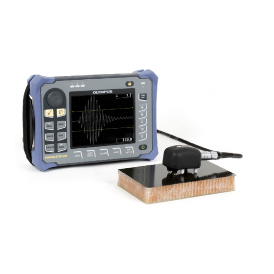
DMTA-10045-01EN, Rev. E, August 2016 Introduction This user’s manual provides operating instructions for the Olympus BondMaster 600 composite bond tester, which uses acoustic and ultrasonic waves to detect surface flaws in various types of composite materials (see Figure i-4 on page 17). The manual’s information is organized to explain the BondMaster 600 technology, safety... -
Page 28: Dmta-10045-01En, Rev. E, August
DMTA-10045-01EN, Rev. E, August 2016 Introduction... -
Page 29: Package Contents
Initial Inspection After the BondMaster 600 has been unpacked and the contents of the carton have been checked against the packing list, a visual inspection and a basic operation test should be performed as follows:... -
Page 30: Contents Of The Case
Let the BondMaster 600 perform the “Power-On Self Test.” Confirm that the “Sign-On” message is displayed. Contents of the Case The BondMaster 600 comes with several key accessories (see Figure 1-1 on page 21): • Calibration certificate (Olympus P/N: B600-CERT [U8010093]). -
Page 31: Figure 1-1 Transport Case Contents
USB to PC cable BondMaster 600 Transport case (may differ from your model) Figure 1‑1 Transport case contents A list of optional accessories available from Olympus can be found in “Accessories, Replacement Parts, and Upgrades” on page 221. Package Contents... - Page 32 DMTA-10045-01EN, Rev. E, August 2016 Chapter 1...
-
Page 33: Overview Of The Bondmaster 600
90 V to 240 V, with a frequency of 50 Hz or 60 Hz. In all of the various test modes in which the BondMaster 600 operates (using a range of probes), the alternating electric current causes oscillations in the piezoelectric crystals in the probes. - Page 34 DMTA-10045-01EN, Rev. E, August 2016 Defect detection in pitch-catch mode is achieved by detecting a greater amplitude oscillation at the receiving crystal. In the pitch-catch mode's RF and IMPULSE test techniques (fixed frequency test), near-surface and far-surface disbonds can be detected.
-
Page 35: Connectors
In carbon fiber or fiberglass composites, the location of the defect can often be estimated using the phase deflection on the instrument screen. Connectors Figure 2-1 on page 25 illustrates the connections of the BondMaster 600 with the charger/adaptor, the microSD card, and a personal computer (PC). DC power plug... -
Page 36: Figure 2-2 The Top End Connectors
DMTA-10045-01EN, Rev. E, August 2016 WARNING Use only the AC power cord supplied with your BondMaster 600, unless specifically instructed in the manual. Using an unauthorized power cord may result in damage to the instrument or serious human injury. The DC power and PROBE connectors are located on the top end of the BondMaster 600 (see Figure 2-2 on page 26). -
Page 37: Figure 2-3 The Connectors Behind The I/O Door
USB port Figure 2‑3 The connectors behind the I/O door The I/O and the VGA OUT connectors are located at the back of the BondMaster 600, in the upper section (see Figure 2-4 on page 28). A rubber cover protects each connector. -
Page 38: Power Requirements
DMTA-10045-01EN, Rev. E, August 2016 I/O connector VGA OUT connector Figure 2‑4 The I/O and VGA OUT connectors Power Requirements The BondMaster 600 is designed to operate using three power supply methods: • Directly from the BondMaster 600 charger/adaptor • Internal lithium-ion battery •... -
Page 39: Charger/Adaptor
DMTA-10045-01EN, Rev. E, August 2016 Charger/adaptor indicator light Power button Figure 2‑5 Location of the BondMaster 600 power button and indicator light 2.3.1 Charger/Adaptor The BondMaster 600 charger/adaptor is provided with every instrument. This charger/adaptor is the primary method for powering the BondMaster 600 with or without a battery installed. -
Page 40: Figure 2-7 Connecting The Charger/Adaptor
DMTA-10045-01EN, Rev. E, August 2016 WARNING The BondMaster 600 charger/adaptor (P/N: EP-MCA-X) is designed to power the BondMaster 600 and charge the lithium-ion battery only (P/N: 600-BAT-L-2 [U8760058]). Do not attempt to charge any other types of batteries, including alkaline batteries in the battery holder (P/N: 600-BAT-AA [U8780295]), and do not attempt to use any other charger/adaptor. -
Page 41: Figure 2-8 Connecting The Dc Power Cable
DMTA-10045-01EN, Rev. E, August 2016 Lift the rubber seal that covers the DC connector on top of the BondMaster 600. Connect the DC output power cable from the charger/adaptor to the DC power connector on top of the BondMaster 600 (see Figure 2-8 on page 31). -
Page 42: Battery Compartment
The battery compartment cover also has a small hole in the bottom center area that is covered on the inside by an environmentally sealed membrane vent. This vent is a safety feature that is required in the event that the BondMaster 600 battery fails and emits gas. This vent must not be punctured. -
Page 43: Figure 2-9 The Battery Compartment
(Olympus P/N: 600-BAT-AA [U8780295]) for extended portable use. WARNING If the BondMaster 600 is to be used with a rechargeable battery, only use the Olympus battery, P/N: 600-BAT-L-2 [U8760058]. Using any other type of battery might cause an explosion and injury. -
Page 44: Lithium-Ion Battery
8 and 10 hours of continuous operation. IMPORTANT The lithium-ion battery is not fully charged when the BondMaster 600 is shipped. You must charge the battery for two to three hours before using battery power to operate the BondMaster 600 (see “Charger/Adaptor” on page 29). -
Page 45: Alkaline Batteries
Connect the alkaline battery holder connector to the BondMaster 600. Position the alkaline battery holder in the battery compartment. Install the battery compartment cover at the back of the BondMaster 600, and then tighten the two thumb screws. Overview of the BondMaster 600... -
Page 46: Microsd Card Installation
A 2 GB microSD card (Olympus P/N: MICROSD-ADP-2GB [U8779307]) can be installed in the BondMaster 600. To install the microSD removable memory card Remove the card from its packaging. Loosen the two thumb screws, and then open the BondMaster 600 I/O door (see Figure 2-12 on page 37). Chapter 2... -
Page 47: Bondmaster 600 Hardware Features
Gently slide the card into the microSD slot until it clicks. NOTE To remove the microSD card, gently push the card into the BondMaster 600 and release. A spring-loaded mechanism will partially eject the card, and then you can grasp the card and remove it from the BondMaster 600. -
Page 48: Hardware Overview
Figure 2-13 on page 38 and Figure 2-14 on page 39 show the main components on the BondMaster 600. Protective rubber bumpers D-rings to attach the optional chest harness (at the four corners) Knob Display window (screen) Keypad Figure 2‑13 Overview of the BondMaster 600 — Front view Chapter 2... -
Page 49: Front Panel And Smartknob
2.5.1.1 Front Panel and SmartKnob The SmartKnob is an important feature of the BondMaster 600, and it is the primary method used to change different parameters within a menu. In this manual, the term “knob” is also used to refer to the SmartKnob. -
Page 50: Keypad
2.5.1.2 Keypad The BondMaster 600 is available with an English, International, Chinese, or Japanese keypad configuration (see Figure 2-16 on page 41 to Figure 2-19 on page 42, and Table 4 on page 43). The text labels on some keys may be replaced by pictograms, depending on the keypad configuration. -
Page 51: Figure 2-16 The Bondmaster 600 English Keypad
DMTA-10045-01EN, Rev. E, August 2016 Figure 2‑16 The BondMaster 600 English keypad Figure 2‑17 The BondMaster 600 international keypad Overview of the BondMaster 600... -
Page 52: Figure 2-18 The Bondmaster 600 Chinese Keypad
DMTA-10045-01EN, Rev. E, August 2016 Figure 2‑18 The BondMaster 600 Chinese keypad Figure 2‑19 The BondMaster 600 Japanese keypad Chapter 2... -
Page 53: Table 4 Keypad Functions
CAL/NULL If this direct function key is pressed once, it nulls (zeros) the BondMaster 600. If this key is pressed and held, a calibration wizard is initiated in RESON (resonance) and MIA (mechanical impedance analysis) modes of operation only. - Page 54 When this key is pressed once (and released), the currently displayed image and settings are saved. When this key is pressed and held, the current BondMaster 600 image is set as the reference memory display. MAIN Provides access to the main menu, which controls functions such as frequency, gain, angle, filters, RF signal, and gate.
-
Page 55: Connectors
2.5.2.1 PROBE Connector The BondMaster 600 is supplied with an 11-pin Fischer (PROBE) connector. The PROBE connector is located at the top of the BondMaster 600, on the left-hand side (see Figure 2-20 on page 45). PROBE connector Figure 2‑20 Location of the PROBE connector... -
Page 56: Input/Output And Vga Out Connectors
Input/Output and VGA OUT Connectors The input/output (I/O) and the VGA OUT connectors are located at the back of the BondMaster 600, in the upper section (see Figure 2-21 on page 46). A rubber cover protects each connector. I/O connector VGA OUT connector Figure 2‑21 The VGA OUT and I/O connectors... -
Page 57: Microsd And Usb Port
2.5.2.3 MicroSD and USB Port On the right-hand side of the BondMaster 600, a door covers the microSD slot and the USB port (see Figure 2-22 on page 48). The I/O door closes against an integral membrane seal to keep liquids away from the unsealed connectors behind it. -
Page 58: Various Hardware Features
CAUTION Do not expose the BondMaster 600 to harsh and wet environments while the I/O door is open. To prevent connector corrosion and damage to the BondMaster 600, keep the I/O door closed and sealed when no cable is connected. -
Page 59: Bondmaster 600 Stand
The BondMaster 600 features an articulating stand for variable viewing angles (see Figure 2-23 on page 49). The stand is attached to the back of the BondMaster 600 with two hard pivot blocks. There is a high-friction coating on the stand surface to help prevent it from sliding. -
Page 60: Display Protection
(Olympus P/N: 600-DP [U8780297]). CAUTION The display window is permanently bonded to the instrument case to fully seal the BondMaster 600. If the display window becomes damaged, the front part of the case must be replaced, along with the keypad. 2.5.4... -
Page 61: Software User Interface
3. Software User Interface This chapter explains the main software screens and menus on the BondMaster 600 composite bond tester. The back of the BondMaster 600 contains a quick guide to the instrument keypad and functions (see Figure 3-1 on page 51). -
Page 62: Figure 3-2 Application Choices On The Quick-Setup Menu
DMTA-10045-01EN, Rev. E, August 2016 • If a PowerLink probe is connected, the BondMaster 600 starts up in the PowerLink recognition screen (see Figure 3-3 on page 52), which lets you automatically set up the instrument for that type of probe. -
Page 63: Navigating The Application Menu
(see Figure 3-3 on page 52), load the program stored in the PowerLink probe, and automatically set up the BondMaster 600 by pressing the A key. Bypass the stored program in the probe and gain access to the BondMaster 600 main inspection screen by pressing the Return key ( 3.1.2... -
Page 64: Figure 3-4 The Main Inspection Screen
DMTA-10045-01EN, Rev. E, August 2016 Figure 3‑4 The main inspection screen NOTE Figure 3-4 on page 54 contains a typical example of the main inspection screen. The screen’s appearance may vary, depending on the application that is chosen or the PowerLink application (program) that is loaded (see Figure 3-2 on page 52 and Figure 3-3 on page 52). -
Page 65: Selecting From The Menus
For more information, see “Displaying Real-Time Readings” on page 58. The BondMaster 600 settings are displayed on the right hand side of the main screen. The displayed settings information can change, depending on the menu key that is pressed. -
Page 66: Displaying All Parameters Simultaneously-All Settings Menu
(and saved); you do not have to use the Enter key. Displaying All Parameters Simultaneously—ALL SETTINGS Menu As an alternative to the operation menu, the BondMaster 600 has the option of displaying all parameters simultaneously using the ALL SETTINGS menu. The ALL SETTINGS menu consists of three main elements: the title bar, the parameters, and the help text (see Figure 3-6 on page 56). -
Page 67: Using The All Settings Menu
EXT HORN (external horn) and AOUT PWR (analog out power). These functions enable the output connectors on the back of the BondMaster 600 (see Figure 2-21 on page 46). To enable these functions, follow the instructions in “Using the ALL SETTINGS Menu”... -
Page 68: Displaying Real-Time Readings
DMTA-10045-01EN, Rev. E, August 2016 NOTE If the BondMaster 600 is being used in noisy conditions, an external horn can be used. The horn connects to the I/O connector on the back of the BondMaster 600 and increases the audible alarm’s sound output to 70 dB (see Table 8 on page 209 for the part specification). -
Page 69: Enabling Real-Time Readings On The Main Inspection Screen
DMTA-10045-01EN, Rev. E, August 2016 Figure 3‑7 Example of LIVE AMPL, LIVE VERT, LIVE HORZ, and LIVE ANGL Figure 3‑8 Example of VOLTS P‑P 3.4.1 Enabling Real-Time Readings on the Main Inspection Screen The real-time readings are enabled through the ADV SETUP menu key ( To enable the real-time readings bar on the main inspection screen Press the ADV SETUP menu key ( Press the B key. -
Page 70: Enabling Real-Time Readings In Full-Screen Mode - Full Next Key
DMTA-10045-01EN, Rev. E, August 2016 Press the C key. Press the FULL NEXT key ( ) to navigate to the desired type and/or location. NOTE Only TOP LEFT and TOP RIGHT are valid locations for the real-time readings on the main inspection screen. -
Page 71: Dmta-10045-01En, Rev. E, August
DMTA-10045-01EN, Rev. E, August 2016 Press the B key. Press the E key. Press the B key. Press the FULL NEXT key ( ) to navigate to the desired type and/or location. Rotate the knob to make a selection. Press the FULL NEXT key ( ) to navigate to another type and/or location. - Page 72 DMTA-10045-01EN, Rev. E, August 2016 Chapter 3...
-
Page 73: Initial Setup
Setting the User Interface Language and Decimal Symbol You can configure the BondMaster 600 to present the user interface in the following languages: English, French, Spanish, German, Japanese, Chinese, Russian, Swedish, Italian, Portuguese, Norwegian, Hungarian, Polish, Dutch, and Czech. You can also change the character that represents the decimal of a number. -
Page 74: Setting The Clock
Setting the Clock The BondMaster 600 has a built-in date and time clock. You can set the date and the time, and select their respective format. The BondMaster 600 saves all inspection results with their acquisition date. -
Page 75: Changing The Display Settings
Changing the Display Brightness You can adjust the BondMaster 600 display brightness by changing the backlight intensity. The display brightness can be set at 0 %, 25 %, 50 %, 75 %, or 100 %. -
Page 76: Adjusting Auto Erase
DMTA-10045-01EN, Rev. E, August 2016 display brightness is set to 50 %. The transflective color display of the BondMaster 600 reflects ambient light and becomes brighter in direct light. With brighter ambient conditions, you can set the display BRIGHTNESS to a lower percentage. -
Page 77: Selecting The Startup Screen
Activating the Crosshairs You can set the BondMaster 600 to display crosshairs to better highlight the position of the null (see Figure 4-2 on page 68). Crosshairs are available only for XY screens (with or without split screen), but functions in ALL modes. -
Page 78: Figure 4-2 Crosshairs And The Null Point
DMTA-10045-01EN, Rev. E, August 2016 Figure 4‑2 Crosshairs and the NULL point Chapter 4... -
Page 79: Control Functions
DMTA-10045-01EN, Rev. E, August 2016 5. Control Functions This chapter provides explanations of the control functions on the BondMaster 600 composite bond tester. PowerLink The PowerLink feature enables the BondMaster 600 to automatically recognize Olympus PowerLink BondMaster probes when they are connected to the instrument. -
Page 80: Bondmaster 600 Controls
At this point, if the PowerLink function has been enabled, the settings will be loaded into the BondMaster 600. If the Powerlink function has been disabled, this screen will be bypassed. In either case, the BondMaster 600 will next proceed to the main inspection screen. -
Page 81: Power And Lock Buttons
5.2.3 Function Keys The function keys located on the right side of the BondMaster 600 are used to select instrument parameters for adjustment. When a function key is pressed, the parameter located in the box displayed directly beside that key (A, B, C, D, or E) is highlighted. -
Page 82: Smartknob
BondMaster 600. 5.2.6 Hidden Function — Screen Capture On the BondMaster 600 instrument, you can send a screen-capture image file to the removable (external) microSD card by holding the MAIN menu key ( ), and then pressing the REF SAVE key ( ). -
Page 83: Modes And Menus
DMTA-10045-01EN, Rev. E, August 2016 Modes and Menus The BondMaster 600 menus described in this section are opened by pressing the corresponding menu keys, which are described in “Menu Keys” on page 71. NOTE The BondMaster 600 menus vary, depending on the following: •... -
Page 84: Figure 5-4 The Pc (Rf) Main Menu
DMTA-10045-01EN, Rev. E, August 2016 The following parameters can be adjusted on the PC (RF) main menu (see Figure 5-4 on page 74): • FREQ (frequency) • RF GAIN • WIDTH • GATE • RF DISPLAY • CYCLES • H/V GAIN (horizontal/vertical gain) •... - Page 85 DMTA-10045-01EN, Rev. E, August 2016 Changing Parameters in the PC (RF) Main Menu NOTE The following information is applicable when the BondMaster 600 mode is set to PC (RF) and the MAIN menu key ( ) has been pressed. FREQ (frequency) The FREQ (frequency) setting determines the frequency of the tone burst.
- Page 86 DMTA-10045-01EN, Rev. E, August 2016 GATE The GATE setting controls the position on the RF DISPLAY where the XY flying dot display is computed. The GATE position determines the signal amplitude and phase on the XY display. To obtain the best results, set the GATE to the left of the first maximum peak on the RF DISPLAY, or on its maximum peak.
- Page 87 C key, and then rotate the knob to the desired repetition rate. PRB DRV (probe drive) The BondMaster 600 has three levels of probe drive: LOW, MEDIUM, and HIGH. The approximate peak-to-peak voltages are 2 V, 6 V, and 12 V, respectively.
-
Page 88: Pc Swept Mode - Main Menu
DMTA-10045-01EN, Rev. E, August 2016 5.3.2 PC Swept Mode — MAIN Menu In pitch-catch (PC) swept mode, the probe is excited by a signal that is swept from a specified starting and ending frequency. The displayed signal represents the excitation frequency that is swept (see Figure 5-5 on page 78). Figure 5‑5 The PC Swept display The following parameters can be adjusted on the PC Swept main menu: •... - Page 89 DMTA-10045-01EN, Rev. E, August 2016 Changing the Parameters in the PC Swept Main Menu NOTE The following information is applicable when the BondMaster 600 is set to PC Swept mode and the MAIN menu key ( ) has been pressed.
- Page 90 DMTA-10045-01EN, Rev. E, August 2016 FRQ1 TRACK (frequency 1 tracking) The FRQ1 TRACK (frequency 1 tracking) parameter is set to OFF by default. To change the FRQ1 TRACK setting, press the MAIN menu key ( ) followed by the A key, and then rotate the knob to the desired frequency 1 tracking value. This control is only available when the display is set to SPEC+XY or SPECTRUM, and it is easier to work with in the SPEC+XY RUN.
-
Page 91: Mia Mode - Main Menu
C key, and then rotate the knob to the desired horizontal gain value. V GAIN (vertical gain) The V GAIN (vertical gain) setting controls the BondMaster 600 vertical gain. To change the V GAIN setting, the MAIN menu key ( ) followed by the D key, and then rotate the knob to the desired vertical gain value. - Page 92 For details on GAIN, H GAIN, V GAIN, and PRB DRV parameter adjustments, see “PC Swept Mode — MAIN Menu” on page 78. Parameter descriptions are based on the presumption that the BondMaster 600 is set to MIA mode and the MAIN menu key ( ) has been pressed.
-
Page 93: Reson Mode - Main Menu
DMTA-10045-01EN, Rev. E, August 2016 5.3.4 RESON Mode — MAIN Menu The RESON (resonance) mode uses a probe that is tuned to have a resonance at a particular frequency. When resonance mode is selected, a frequency sweep is done to determine the resonance frequency of the probe. -
Page 94: Pc Rf Mode - Disp/Dots Menu
NOTE For parameter adjustment details, see “MIA Mode — MAIN Menu” on page 81. Parameter descriptions are based on the presumption that the BondMaster 600 is set to RESON mode and the MAIN menu key ( ) has been pressed. - Page 95 DMTA-10045-01EN, Rev. E, August 2016 Changing the Parameters in the PC RF DISP/DOTS (Display/Dots) Menu NOTE The following information is applicable when the BondMaster 600 is set to PC RF mode and the DISP/DOTS menu key ( ) has been pressed.
-
Page 96: Figure 5-8 The Run Setting
GRID The GRID setting controls the condition of the BondMaster 600 display grid. Five screen grid types are available: OFF, 10 × 10, FINE, COARSE, and WEB. By default, the BondMaster 600 uses a 10 × 10 grid. - Page 97 STORE NEXT The STORE NEXT setting allows you to store dot positions on the BondMaster 600 display. When activated, STORE NEXT stores the dot location, along with a numerical value on the screen (see Figure 5-9 on page 88). Control Functions...
-
Page 98: Figure 5-9 The Stored Dots
The ERASE DOT function allows you to erase the current dot location. To erase a dot location, press the C key. Press the C key repeatedly to erase dots one at a time, in the reverse order that they were written (stored) on the BondMaster 600 screen. Chapter 5... - Page 99 BondMaster 600 display screen. This image is viewable after the erase button is pressed. To set a reference image for the BondMaster 600 display screen, press the E key. Alternatively, the set reference parameter can be activated by pressing and holding the REF SAVE direct function key ( ) until an alert sound is heard.
-
Page 100: Pc Swept Mode - Disp/Dots Menu
DMTA-10045-01EN, Rev. E, August 2016 Figure 5‑10 D ERASE fine (left) and coarse (right) functions NOTE The display erase function is not available if variable persistence (PERSIST) is activated. PERSIST (variable persistence) The PERSIST (variable persistence) setting enables automatic screen erase. You can set the display on an impedance plane (not sweep) so that the signal traces on the screen will be erased after a predetermined amount of time. -
Page 101: Mia Mode - Disp/Dots Menu
For details on RUN, CURSOR, GRID, and D ERASE parameter adjustments, see “PC RF Mode — DISP/DOTS Menu” on page 84. Parameter descriptions are based on the presumption that the BondMaster 600 is set to PC Swept mode and the DISP/DOTS menu key ( ) has been pressed. -
Page 102: Reson Mode - Disp/Dots Menu
For parameter adjustment details, see “PC RF Mode — DISP/DOTS Menu” on page 84. Parameter descriptions are based on the presumption that the BondMaster 600 is set to MIA mode and the DISP/DOTS menu key ( ) has been pressed. -
Page 103: Pc Rf Mode - Alarm Menu In Rf Run
DWELL • HORN NOTE The following information is applicable when the BondMaster 600 is set to PC (RF) mode and the ALARM menu key ( ) has been pressed. RF ALARM The RF ALARM setting controls the RF alarm type and can be set to OFF, POS (positive), or NEG (negative). -
Page 104: Figure 5-11 Alarm Threshold Control
DMTA-10045-01EN, Rev. E, August 2016 Figure 5‑11 Alarm threshold control BOTTOM The BOTTOM setting controls the alarm’s lower threshold. The displayed percentage is a percentage of the total screen height. An example of this control is shown in Figure 5-11 on page 94. To change the BOTTOM alarm threshold setting, press the C key, and then rotate the knob to the desired alarm threshold value. -
Page 105: Figure 5-12 Alarm Dwell Control
DMTA-10045-01EN, Rev. E, August 2016 Figure 5‑12 Alarm DWELL control HORN The HORN setting controls the alarm horn. The alarm horn has two options: OFF or ON (see Figure 5-13 on page 95). To change the HORN setting, press the E key, and then rotate the knob to the desired setting. -
Page 106: Pc Rf Mode - Alarm Menu In Rf+Xy And Xy Run
DMTA-10045-01EN, Rev. E, August 2016 5.3.10 PC RF Mode — ALARM Menu in RF+XY and XY RUN The following parameters can be adjusted on the PC (RF) mode ALARM menu in RF+XY and XY RUN: • RF ALARM (see “PC RF Mode — ALARM Menu in RF RUN” on page 93) •... - Page 107 For DWELL and HORN parameter adjustment details, see “PC RF Mode — ALARM Menu in RF RUN” on page 93. Parameter descriptions are based on the presumption that the BondMaster 600 is set to PC Swept mode and the ALARM menu key ( has been pressed.
-
Page 108: Figure 5-14 The Pc Swept Mode's Alarm Dwell Setting Control
DMTA-10045-01EN, Rev. E, August 2016 Figure 5‑14 The PC Swept mode’s alarm DWELL setting control Figure 5‑15 The PC Swept mode’s alarm HORN setting control SHAPE NOTE The SHAPE control is only available when the XY ALM 1 (XY alarm1) or XY ALM 2 (XY alarm 2) have been enabled. -
Page 109: Changing Box Alarm Parameters In Pc Swept Mode
DMTA-10045-01EN, Rev. E, August 2016 The SHAPE setting controls the shape of the alarm threshold. It can be set to BOX, SECTOR, or CIRCLE. To change the shape of the XY ALM 1 (XY alarm 1) threshold, press the ALARM menu key ( ) twice, followed by the A key, and then rotate the knob to the desired alarm shape. -
Page 110: Changing Sector Alarm Parameters In Pc Swept Mode
DMTA-10045-01EN, Rev. E, August 2016 Figure 5‑16 The PC Swept mode’s BOX alarm shape controls To change the shape of the BOX alarm (XY ALM 1 [XY alarm 1] or XY ALM 2 [XY alarm 2]), modify the following parameters: •... -
Page 111: Changing Circle Alarm Parameters In Pc Swept Mode
DMTA-10045-01EN, Rev. E, August 2016 Figure 5‑17 The PC Swept mode’s SECTOR alarm shape controls To change the shape of the SECTOR alarm (XY ALM 1 [XY Alarm 1] or XY ALM 2 [XY Alarm 2]), modify the following parameters: •... -
Page 112: Changing Spectrum Alarm Parameters In Pc Swept Mode
DMTA-10045-01EN, Rev. E, August 2016 Figure 5‑18 The PC Swept mode’s CIRCLE alarm shape controls To change the shape of the CIRCLE alarm (XY ALM 1 [XY Alarm 1] or XY ALM 2 [XY Alarm 2]), modify the following parameters: •... -
Page 113: Mia Mode - Alarm Menu
ALARM Menu” on page 96. For DWELL and HORN details, see “PC RF Mode — ALARM Menu in RF RUN” on page 93. Parameter descriptions are based on the presumption that the BondMaster 600 is set to MIA mode and the ALARM menu key ) has been pressed. -
Page 114: Figure 5-19 The Mia Mode's Alarm Dwell Setting Controls
DMTA-10045-01EN, Rev. E, August 2016 SCAN ALM (scan alarm) The SCAN ALM setting allows you to set up a threshold on the SCAN RUN displays. To change the SCAN ALM setting, press the A key, and then rotate the knob to the desired setting. -
Page 115: Reson Mode - Alarm Menu
Menu” on page 103. For DWELL and HORN details, see “PC RF Mode — ALARM Menu in RF RUN” on page 93. Parameter descriptions are based on the presumption that the BondMaster 600 is set to RESON (resonance) mode and the ALARM menu key ( ) has been pressed. -
Page 116: Mem Menu
DMTA-10045-01EN, Rev. E, August 2016 Figure 5‑21 The RESON mode’s alarm DWELL control Figure 5‑22 The RESON mode’s alarm HORN control 5.3.15 MEM Menu The MEM (memory) menu contains functions for storage of programs and screen (display) images. Various editing functions are provided in this menu for previewing saved data, recalling saved data, editing file names, adding notes, setting a reference image, and erasing saved data. - Page 117 To recall a stored data file, press the MEM menu key ( ), rotate the knob until the desired data file is highlighted, and then press the B key. The BondMaster 600 recalls the data file with the instrument settings that were stored when the data file was saved.
- Page 118 MEM menu key ( ), rotate the knob until the desired data file is highlighted, and then press the C key; a text editor will appear on the BondMaster 600 display. For more information, see “Memory Text Editor” on page 109.
-
Page 119: Memory Text Editor
5.3.16 Memory Text Editor The memory text editor appears on the BondMaster 600 screen when editing the file name or file text fields. This section of the manual provides instructions on how to use this editor to change file names and file notes. -
Page 120: Figure 5-23 The File Manager Menu's Memory Text Editor And Special Buttons
DMTA-10045-01EN, Rev. E, August 2016 Move cursor left Delete character Move cursor right Clear entire line Figure 5‑23 The FILE MANAGER menu’s memory text editor and special buttons Use the knob to select characters, and press the FULL NEXT key ( ) to accept the characters. - Page 121 DMTA-10045-01EN, Rev. E, August 2016 To insert a character using the navigation keys Rotate the knob until the forward ( ) or backward ( ) arrow is highlighted. Press the FULL NEXT key ( ) until the cursor is in the correct location. Use the knob to select characters, and press the FULL NEXT key ( ) to accept characters.
-
Page 122: Advanced Setup Menu - Adv Setup Menu Key
A key. Rotate the knob to select the desired application, and then press Or, to exit the menu, press the Return key ( Figure 5‑24 The APPL SELECT menu The available applications allow you to quickly set up the BondMaster 600 for commonly used bond testing inspections. Chapter 5... -
Page 123: Figure 5-25 The All Settings Menu (First Of Two Screens)
DMTA-10045-01EN, Rev. E, August 2016 NOTE The BondMaster 600 applications are designed for quick setup of the instrument. However, always follow published maintenance procedures when inspecting. ALL SETTINGS The ALL SETTINGS menu gives you access to all BondMaster 600 functions. -
Page 124: Figure 5-26 The Password Menu
DMTA-10045-01EN, Rev. E, August 2016 NOTE The BondMaster 600 does not require you to use the Enter key to save the selection made on any of its menus. Instead, the selected (and displayed) value is automatically saved. Opens the calibration menu (only for MIA and Resonance modes). - Page 125 ) twice, followed by the C key, and then enter the option code for the upgrade. For more information on this feature, contact your local Olympus representative. Contact information for your region can be found by visiting the Olympus website at http://www.olympus-ims.com/en/contact-us/. ABOUT This feature displays the instrument’s configuration and other important...
-
Page 126: Figure 5-27 The About Menu
To exit, press the Return key ( Displays regulatory information for the BondMaster 600 (see Figure 5-28 on page 117). To access the REG (Regulatory) menu, press the ADV SETUP menu key ( ) twice, followed by the D key and then the E key. -
Page 127: Figure 5-28 The Regulatory Screen
DMTA-10045-01EN, Rev. E, August 2016 Figure 5‑28 The REGULATORY SCREEN UPGRADE Provides access to the communication link between your BondMaster 600 and a PC on which the BondMaster PC software is installed. NOTE BondMaster PC software is required to update the BondMaster 600 operating software. - Page 128 LED TEST—Checks if the BondMaster 600 LEDs (light-emitting diodes) are operational. The LEDs are located at the top-left corner of the BondMaster 600, and are marked with the numbers 1, 2, and 3. During the test, each of the LEDs consecutively illuminate in a sequence of green, yellow/orange, and red.
-
Page 129: Figure 5-29 The Reset Menu
Parameters reset Clears only the instrument settings, and returns the BondMaster 600 to its default settings. Storage reset Clears all stored programs and screen images. Master reset Clears the BondMaster 600 settings, stored programs, and screen images, and returns the BondMaster 600 to its default settings. Control Functions... - Page 130 DMTA-10045-01EN, Rev. E, August 2016 Chapter 5...
-
Page 131: Applications
BondMaster 600 applications. While other procedures may lead to equivalent results, the steps and recommendations below reflect what Olympus has determined to be the optimal way to use the BondMaster 600 instrument’s numerous features. In consequence, the number of steps and operations are reduced to a minimum. -
Page 132: Common Bondmaster 600 Applications
The following procedure is also intended to demonstrate the various important or new features of the BondMaster 600 and as such, shows alternate displays at the end. This purpose of this procedure is to detect and differentiate between near-side disbonds and far-side disbonds. -
Page 133: Figure 6-1 Materials - Skin-To-Core Disbonds In Flat Or Constant Geometry
Pitch-catch probe for general use; tip spacing 14 mm. P/N: S-PC-P14 [U8800601] To set the initial BondMaster 600 configuration Connect the probe and the cable to the PROBE connector of the BondMaster 600. When prompted, press CONTINUE (A key) to accept the PowerLink probe information. -
Page 134: Figure 6-2 The Skin To Core Disbonds (Flat) Application
DMTA-10045-01EN, Rev. E, August 2016 Figure 6‑2 The Skin To Core Disbonds (Flat) application To calibrate the signals Press the MAIN menu key ( ) once, and set the FREQ (A key) to 11 kHz using the knob. Set the probe tips over a good area of the standard, adjust the gain using the GAIN key ( ), and then ensure that the signal in the RF view (left) is contained between 1 to 2 vertical divisions (see Figure 6-3 on page 124). -
Page 135: Figure 6-4 Detecting The Far-Side And Near-Side Disbonds
Figure 6‑4 Detecting the far‑side and near‑side disbonds GATE setup NOTE By default, the GATE is set to AUTO. In AUTO mode the BondMaster 600 automatically detects the peak signal from the RF view and uses it to construct the XY flying dot view. -
Page 136: Figure 6-5 The Recommended Gate Position
DMTA-10045-01EN, Rev. E, August 2016 Figure 6‑5 The recommended GATE position IMPULSE display NOTE IMPULSE mode applies an envelope filter over the RF signal. (The name “IMPULSE” originates from earlier BondMaster products.) If preferred, set the RF DISPLAY (E key) to IMPULSE (see Figure 6-6 on page 127). -
Page 137: Figure 6-6 The Impulse Display
DMTA-10045-01EN, Rev. E, August 2016 Figure 6‑6 The IMPULSE display When in IMPULSE mode, you can increase the WIDTH (C key) to spread the signal peak over fewer divisions. To optimize the identification of near-side and far-side disbonds Press the RUN key ( ) once to display the XY flying dot single view. -
Page 138: Figure 6-7 The Scan Over The Disbonds
DMTA-10045-01EN, Rev. E, August 2016 Figure 6‑7 The scan over the disbonds While on the MAIN menu, press ANGLE (E key), and then adjust the signal angle so the far-side disbond goes down and the near-side disbond goes up (see Figure 6-8 on page 128). -
Page 139: Figure 6-9 Adjusting The H Gain And V Gain
DMTA-10045-01EN, Rev. E, August 2016 Figure 6‑9 Adjusting the H GAIN and V GAIN Press the FREEZE key ( ) again to restart the acquisition. Press the FULL NEXT key ( ) to toggle to full-screen mode. The readings display in real time the amplitude (A) and phase (°) of the XY flying dot (see Figure 6-10 on page 129). -
Page 140: Figure 6-11 Run 1 - Rf Signal
DMTA-10045-01EN, Rev. E, August 2016 The new SCAN display and alternate RUNs To instantly switch between various signal representations during inspection (in full or normal screen mode), press the RUN key ( ) repeatedly to obtain the desired RUN. The available RUNs are shown in Figure 6-11 on page 130 through Figure 6-15 on page 132. -
Page 141: Figure 6-13 Run 3 - Xy Fly Dot
DMTA-10045-01EN, Rev. E, August 2016 Figure 6‑13 RUN 3 — XY FLY DOT Figure 6‑14 RUN 4 — XY + SCAN Applications... -
Page 142: Figure 6-15 Run 5 - Scan
DMTA-10045-01EN, Rev. E, August 2016 Figure 6‑15 RUN 5 — SCAN To obtain clearer phase readings in the SCAN views, it is recommended to NULL the probe in the air. To fine-tune the instrument settings Depending on your requirements, set the alarm box parameters, horn, or external horn (louder). -
Page 143: Detecting Skin-To-Core Disbonds In Honeycomb Composite - Tapered Or Varying Geometry Using Pc Swept Technique
DMTA-10045-01EN, Rev. E, August 2016 Figure 6‑16 The list of all parameters 6.1.2 Detecting Skin-to-Core Disbonds in Honeycomb Composite — Tapered or Varying Geometry Using PC Swept Technique The pitch-catch (PC) swept technique is ideal for inspecting honeycomb composite parts with tapered or varying geometry. This technique works well on a variety of skin and cores, but it works especially well with aluminum honeycomb cores. -
Page 144: Figure 6-17 Materials - Skin-To-Core Disbonds In Tapered Geometry
Pitch-catch probe for general use; tip spacing 14 mm. P/N: S-PC-P14 [U8800601] To set the initial BondMaster 600 configuration Connect the probe and the cable to the PROBE connector of the BondMaster 600. When prompted, press CONTINUE (A key) to accept the PowerLink probe information. -
Page 145: Figure 6-18 The Skin To Core Disbonds (Tapered) Application
DMTA-10045-01EN, Rev. E, August 2016 Figure 6‑18 The Skin To Core Disbonds (Tapered) application To calibrate the signals Press the MAIN menu key ( ) once, and then use the knob to set the START FREQ (C key) to 10 kHz and the STOP FREQ (D key) to 40 kHz. Place the probe tips on a good part of the standard, press the GAIN key ( and then use the knob to adjust the gain until the swept figure is contained between two divisions inside the alarm box (see Figure 6-19 on page 135). -
Page 146: Figure 6-20 The Full-Screen Display Of The Scan
DMTA-10045-01EN, Rev. E, August 2016 While the probe is still on a good part of the standard, press the CAL NULL key Scan over the defects and ensure that the signal goes outside the alarm box. Readjust the GAIN as needed. Press the FULL NEXT key ( ) to display the full screen, and then scan over defects again (see Figure 6-20 on page 136). -
Page 147: Detecting Smaller Disbonds In Honeycomb Composite - Mechanical Impedance Analysis (Mia) Technique
The smaller tips of the MIA probes, combined with the expanded frequency range of the BondMaster 600, are ideal for detecting smaller defects in honeycomb composites. This procedure demonstrates how to use the MIA test mode to detect defects in honeycomb composite assemblies using a suggested test frequency. -
Page 148: Figure 6-22 Materials - Smaller Disbonds Using Mia Technique
Right angle MIA probe, 13 mm (0.5 in.) tip. P/N: S-MP-3 [U8010011] To set the initial BondMaster 600 configuration Connect the probe and the cable to the PROBE connector of the BondMaster 600. When prompted, press CONTINUE (A key) to accept the PowerLink probe information. -
Page 149: Figure 6-23 The Smaller Disbonds And Repair Identification Application
DMTA-10045-01EN, Rev. E, August 2016 Figure 6‑23 The Smaller Disbonds and Repair Identification application To calibrate the signals Press the MAIN menu key ( ) once, and then set the FREQ (A key) to 10 kHz using the knob. Place the probe tip on a good part of the standard (CFRP side), and then press the CAL NULL key ( Slowly scan over one of the 13 mm (0.5 in.) disbonds, and then press the FREEZE key (... -
Page 150: Figure 6-25 The Signal Angle Adjusted Upwards
DMTA-10045-01EN, Rev. E, August 2016 Press ANGLE (E key), and then adjust the signal angle so that the signal points upwards towards the alarm box (see Figure 6-25 on page 140). Figure 6‑25 The signal angle adjusted upwards Press the GAIN key ( ), and then adjust the signal amplitude so that the disbond signal enters the alarm box and extends approximately 5 divisions from the null position (cross hairs) [see Figure 6-26 on page 140]. -
Page 151: Figure 6-27 The Second Scan Over The Disbond
DMTA-10045-01EN, Rev. E, August 2016 Press the FREEZE key ( ) to unfreeze the acquisition, and then press the FULL NEXT key ( ) to display the full screen. Scan over the 13 mm (0.5 in.) disbond again (see Figure 6-27 on page 141). Figure 6‑27 The second scan over the disbond To fine-tune the instrument settings Depending on your requirements, set the alarm box parameters, horn, or external... -
Page 152: Detecting Repaired Areas (Potting) In Honeycomb Composite - Mechanical Impedance Analysis (Mia) Technique
DMTA-10045-01EN, Rev. E, August 2016 Figure 6‑28 The list of all parameters 6.1.4 Detecting Repaired Areas (Potting) in Honeycomb Composite — Mechanical Impedance Analysis (MIA) Technique As MIA technology measures the mechanical impedance (or stiffness) of materials, it displays a high contrast between a repaired/potted area (which is stiff) and a disbond (which has low mechanical resistance). -
Page 153: Figure 6-30 The Smaller Disbonds And Repair Identification Application
Right angle MIA probe, 13 mm (0.5 in.) tip. P/N: S-MP-3 [U8010011] To set the initial BondMaster 600 configuration Connect the probe and the cable to the PROBE connector of the BondMaster 600. When prompted, press CONTINUE (A key) to accept the PowerLink probe information. -
Page 154: Figure 6-31 Adjusting The Dot Position
DMTA-10045-01EN, Rev. E, August 2016 To calibrate the signals Press the DISP/DOTS menu key ( ) once, and then set the POSITION (C key) to CENTER. Press the ALARM menu key ( ), and then set the XY ALM 1 (B key) to OFF. Place the probe tip on a good part of the standard, and then press the CAL NULL key ( Lift the probe into the air to observe the dot’s movement;... -
Page 155: Figure 6-32 The Scan Over The Disbond And Repaired Area
DMTA-10045-01EN, Rev. E, August 2016 Figure 6‑32 The scan over the disbond and repaired area Press the MAIN menu key ( ), then press ANGLE (E key) and adjust the signal angle so that the disbond signal points upwards at 90° (see Figure 6-33 on page 145). -
Page 156: Figure 6-34 Adjusting The Signal Amplitude
DMTA-10045-01EN, Rev. E, August 2016 Figure 6‑34 Adjusting the signal amplitude Press the FREEZE key ( ) to unfreeze the acquisition, press the FULL NEXT key ( ) to display the full screen, and then slowly scan over the disbond and repaired area again (see Figure 6-35 on page 146). -
Page 157: Inspecting Metal-To-Metal Bonds - Resonance Technique
DMTA-10045-01EN, Rev. E, August 2016 To fine-tune the instrument settings Depending on your requirements, set the alarm box parameters, horn, or external horn (louder). For more details about alarms, see “Alarms, Connectivity, and Memory Specifications” on page 217. Depending on your requirements, change your real-time readings. The default real-time readings display the XY signal’s live amplitude and phase. -
Page 158: Figure 6-37 Materials - Metal-To-Metal Bonds Using Resonance Technique
250 kHz resonance probe. P/N: S-PR-5 [U8010010] To set the initial BondMaster 600 configuration Connect the probe and the cable to the PROBE connector of the BondMaster 600. When prompted, press CONTINUE (A key) to accept the PowerLink probe information. -
Page 159: Figure 6-38 The Metal To Metal Disbonds Application
If the calibration menu does not appear automatically, press and hold the CAL NULL key ( Hold the probe in the air. The BondMaster 600 should automatically pick the best operating frequency for the probe. When in doubt, press CAL (C key) or change the FREQ (D key) using the knob. -
Page 160: Figure 6-40 The First Dot Recorded
DMTA-10045-01EN, Rev. E, August 2016 To calibrate the signals Install a backing mat or foam under the standard. Doing so will make the readings more stable. Pour a generous amount of couplant onto the standard. Place the probe on a good area of the standard, and then press the CAL NULL key Slowly glide the probe over the first disbond and hold it there. -
Page 161: Figure 6-41 The Second Dot Recorded
DMTA-10045-01EN, Rev. E, August 2016 Figure 6‑41 The second dot recorded Release the probe, and then press the ERASE key ( Press the MAIN menu key ( ) once to display the MAIN menu screen. 10. Adjust the ANGLE (E key) as necessary, so that the dots move up in the XY view. 11. -
Page 162: Figure 6-43 The Second Scan Over The Disbonds
DMTA-10045-01EN, Rev. E, August 2016 12. Press the ALARM menu key ( ) twice to display the XY ALM 1 screen, and then set the BOTTOM (C key) to 30 %. 13. Press the FULL NEXT key ( ) to display the full screen, and then slowly scan over the disbonds and ensure that the dots still match the signal (see Figure 6-43 on page 152). -
Page 163: Detecting Interply Delamination In Composites - General Procedure Using Resonance Technique
DMTA-10045-01EN, Rev. E, August 2016 Figure 6‑44 The list of all parameters 6.1.6 Detecting Interply Delamination in Composites — General Procedure Using Resonance Technique The resonance technique is the recommended method of detecting delamination between composite material layers. The location of the interply delamination (or the thickness of the part) can often be estimated from the signal phase in the XY view. -
Page 164: Figure 6-45 Materials - Delamination In Composites Using Resonance Technique
250 kHz resonance probe. P/N: S-PR-5 [U8010010] To set the initial BondMaster 600 configuration Connect the probe and the cable to the PROBE connector of the BondMaster 600. When prompted, press CONTINUE (A key) to accept the PowerLink probe information. -
Page 165: Figure 6-46 The Delamination And Laminates Inspection Application
If the calibration menu does not appear automatically, press and hold the CAL NULL key ( Hold the probe in the air. The BondMaster 600 should automatically pick the best operating frequency for the probe. When in doubt, press CAL (C key) or change the FREQ (D key) using the knob. -
Page 166: Figure 6-48 The First Dot Recorded
DMTA-10045-01EN, Rev. E, August 2016 To calibrate the signals Install a backing mat or foam under the standard. Doing so will make the readings more stable. Pour a generous amount of couplant onto the standard. Place the probe on a good area of the standard, and then press the CAL NULL key Slowly glide the probe over the first disbond and hold it there. -
Page 167: Figure 6-49 The Second Dot Recorded
DMTA-10045-01EN, Rev. E, August 2016 Figure 6‑49 The second dot recorded Slowly glide the probe over the third disbond, and then press STORE NEXT (A key) to record the third dot (see Figure 6-50 on page 157). Figure 6‑50 The third dot recorded Release the probe, and then press the ERASE key ( 10. -
Page 168: Figure 6-51 The Gain Adjusted To Set The Highest Dot
DMTA-10045-01EN, Rev. E, August 2016 12. Adjust the GAIN (B key) to set the highest dot at approximately 90 % of the screen height (see Figure 6-51 on page 158). Figure 6‑51 The GAIN adjusted to set the highest dot 13. -
Page 169: Figure 6-53 The Alternate Display Of Amplitude And Phase
DMTA-10045-01EN, Rev. E, August 2016 To fine-tune the instrument settings Depending on your requirements, set the alarm box parameters, horn, or external horn (louder). For more details about alarms, see “Alarms, Connectivity, and Memory Specifications” on page 217. Depending on your requirements, change your real-time readings. The default real-time readings display the XY signal’s live amplitude and phase. -
Page 170: Advanced Guide For Oem Procedure And Application Development Using
Analyzing Frequency Response in Honeycomb Composite — Selecting the Best Inspection Frequency Using PC Swept Technique The pitch-catch (PC) Swept mode of the BondMaster 600 features a new SPECTRUM representation. This representation is useful for understanding the frequency response of a given test specimen, and helps you choose the best operating frequency. -
Page 171: Figure 6-55 Materials - Analyzing Frequency Response Using Pc Swept
Pitch-catch probe for general use; tip spacing 14 mm. P/N: S-PC-P14 [U8800601] To set the initial BondMaster 600 configuration Connect the probe and the cable to the PROBE connector of the BondMaster 600. When prompted, press CONTINUE (A key) to accept the PowerLink probe information. -
Page 172: Figure 6-56 The Skin To Core Disbonds (Tapered) Application
DMTA-10045-01EN, Rev. E, August 2016 Select the Skin To Core Disbonds (Tapered) application, and then press accept (see Figure 6-56 on page 162). Figure 6‑56 The Skin To Core Disbonds (Tapered) application Press the MAIN menu key ( ) once, and set the SW. RATE (E key) to LOW. When developing an application or procedure, the lower sweep rate setting usually provides the best results. -
Page 173: Figure 6-57 The Swept Figure Between Two Divisions
DMTA-10045-01EN, Rev. E, August 2016 First-Pass Analysis IMPORTANT This sub-section shows you how you can use the first probe pass to “clean up” the spectrum view so that subsequently with the second probe pass you can focus only on the useful frequencies. This is particularly important for fiberglass or aluminum skin materials, because they usually return more signals to the pitch-catch probe, which can be misleading when doing the frequency analysis. -
Page 174: Figure 6-58 The Background Reference Signal
DMTA-10045-01EN, Rev. E, August 2016 Figure 6‑58 The background reference signal Adjust the FRQ1 TRACK (A key) or FRQ2 TRACK (B key) as necessary, to select (highlight) up to two specific frequencies. This is useful for identifying the various peaks observed. Slowly scan over defects, and carefully observe the frequency spectrum (right view), in particular the amplitude component (top right) [see Figure 6-59 on page 165]. -
Page 175: Figure 6-59 The Frequency Spectrum View (Right Side Of Screen)
DMTA-10045-01EN, Rev. E, August 2016 Figure 6‑59 The frequency spectrum view (right side of screen) After you have identified the lower and upper limits, press the MAIN menu key ), and then enter these limits as the START FREQ and STOP FREQ values. Second-Pass Analysis To focus on the defects (second probe pass) ... -
Page 176: Finding The Best Frequency To Inspect Honeycomb Composite - Mechanical Impedance Analysis (Mia) Technique
DMTA-10045-01EN, Rev. E, August 2016 Observe the frequency tracking signal in the XY view to determine whether the selected frequencies will enable an easy test or not (see Figure 6-60 on page 166). Figure 6‑60 The frequency‑tracking signal trace 6.2.2 Finding the Best Frequency to Inspect Honeycomb Composite —... -
Page 177: Figure 6-61 Materials - Finding The Best Frequency Using The Mia Technique
Right angle MIA probe, 13 mm (0.5 in.) tip. P/N: S-MP-3 [U8010011] To set the initial BondMaster 600 configuration Connect the probe and the cable to the PROBE connector of the BondMaster 600. When prompted, press CONTINUE (A key) to accept the PowerLink probe information. -
Page 178: Figure 6-62 The Smaller Disbonds And Repair Identification Application
DMTA-10045-01EN, Rev. E, August 2016 Select the Smaller Disbonds and Repair Identification application, and then press to accept (see Figure 6-62 on page 168). Figure 6‑62 The Smaller Disbonds and Repair Identification application To select the frequency Make sure that you can locate all defects on the reference standard. Press and hold the CAL NULL key ( ) to open the CAL (calibration) screen. -
Page 179: Figure 6-63 The Signal For The Smaller Defect
If necessary, select the best operating frequency for your needs by adjusting the FREQ (D key) using the knob (see Figure 6-65 on page 170). In many situations, the BondMaster 600 automatically picks the best operating frequency. However, for some more complex or noisier applications, it is recommended to manually select the frequency. -
Page 180: Figure 6-65 Selecting The Best Operating Frequency
DMTA-10045-01EN, Rev. E, August 2016 NOTE a) Prioritize negative peaks over positive peaks. b) In case you have multiple peaks, prioritize the first (left) peak over the peaks on the right side. When in doubt, repeat the frequency selection steps and ensure that you maintain a constant pressure on the probe. -
Page 181: Figure 6-66 Adjusting The Angle To Move The Dot Upwards
DMTA-10045-01EN, Rev. E, August 2016 Lift the probe into the air, then press the MAIN menu key ( ) and adjust the ANGLE (E key) so that the dot moves upwards in the XY view (see Figure 6-66 on page 171). Figure 6‑66 Adjusting the angle to move the dot upwards If necessary, press the GAIN key ( ) and adjust the GAIN to keep the air... -
Page 182: Figure 6-67 The Gain Adjustment To The Air Signal Dot
DMTA-10045-01EN, Rev. E, August 2016 Figure 6‑67 The GAIN adjustment to the air signal dot Place the probe tip on a defect-free section, press the CAL NULL key ( ) again, and then slowly scan over the defect(s); make sure that the detection is satisfactory, and if necessary, adjust the GAIN, H GAIN, or V GAIN (see Figure 6-68 on page 172). -
Page 183: Bondmaster Pc Software
BondMaster 600 instrument settings. The BondMaster PC software program is included on CD-ROM as a standard accessory with the BondMaster 600. This program allows a PC (computer) to communicate with the BondMaster 600. -
Page 184: Figure 7-1 Bondmaster Pc Device Menu
DMTA-10045-01EN, Rev. E, August 2016 Figure 7‑1 BondMaster PC Device menu In the Capture Screen dialog box, click Start Capture (see Figure 7-2 on page 174). Figure 7‑2 The Capture Screen dialog box When the BondMaster PC has obtained the current instrument screen image, proceed as follows: Chapter 7... -
Page 185: Instrument Software Upgrade
Save the image to the PC hard drive or another memory device. Instrument Software Upgrade BondMaster PC allows you to upgrade the BondMaster 600 instrument software via a USB connection. The instrument software to upgrade must first be downloaded via the internet or other means, and then saved to a file location on the PC. -
Page 186: Figure 7-4 The Upgrade Menu
DMTA-10045-01EN, Rev. E, August 2016 Figure 7‑4 The UPGRADE menu Connect the battery charger to the BondMaster 600. A message is displayed that indicates whether or not the battery charger is connected (see Figure 7-5 on page 176 and Figure 7-6 on page 177). -
Page 187: Figure 7-6 The Message Indicating The Battery Charger Is Connected
Figure 7‑6 The message indicating the battery charger is connected NOTE The software upgrade will not proceed until the BondMaster 600 battery charger is connected to the BondMaster 600 instrument. On the BondMaster PC Utilities menu, select Upgrade (see Figure 7-7 on page 177). -
Page 188: Pdf Creation
Click Start to begin the update. When the software update process has been completed, turn off the BondMaster 600, and then turn it back on again to activate the upgrade. PDF Creation BondMaster PC allows you to export inspection reports to a PC hard drive or memory device. -
Page 189: Figure 7-9 Files In The Left Pane Of The Bondmaster Pc Window
DMTA-10045-01EN, Rev. E, August 2016 Figure 7‑9 Files in the left pane of the BondMaster PC window Selection for exporting all files Selection for exporting a single file Figure 7‑10 The File menu To export all data using the Export All Files As Adobe Acrobat (PDF) option ... -
Page 190: Commands
DMTA-10045-01EN, Rev. E, August 2016 Commands BondMaster PC lets you issue single read, write, or execute commands. To view the full list of commands On the Help menu, select Remote Command (see Figure 7-11 on page 180). The command list opens in a separate window using the PC’s default software for viewing PDF files. -
Page 191: Figure 7-13 The Issue Command Dialog Box
In the Issue Command dialog box, click Send (see Figure 7-13 on page 181). Press Enter on your PC keyboard. The BondMaster 600 remote command convention is as follows: • Read (R) commands end with “?”... -
Page 192: Figure I-4 Bondmaster 600
All commands end with a Carriage Return and Line Feed (entered as “\r\n”). Any space in a Write command should be replaced with an underscore character. For example, for FRQ NEG, use FRQ_NEG. Table 7 BondMaster 600 remote commands Range / valid strings Command... - Page 193 DMTA-10045-01EN, Rev. E, August 2016 Table 7 BondMaster 600 remote commands (continued) Range / valid strings Command Description R/W/X Min. Max. ALMXY1SODIA Alarm 1 Sector 263.0 Outer Diameter ALMXY1SSANG Alarm 1 Sector 359.0 Start Angle ALMXY1SEANG Alarm 1 Sector 359.0...
-
Page 194: Table 7 Bondmaster 600 Remote Commands
DMTA-10045-01EN, Rev. E, August 2016 Table 7 BondMaster 600 remote commands (continued) Range / valid strings Command Description R/W/X Min. Max. ALMXY2SEANG Alarm 2 Sector 359.0 End Angle ALMXY2CRAD Alarm 2 Circle 50.0 Radius ALMXY2CHOR Alarm 2 Circle 99.5 Horizontal... - Page 195 DMTA-10045-01EN, Rev. E, August 2016 Table 7 BondMaster 600 remote commands (continued) Range / valid strings Command Description R/W/X Min. Max. ALMRFTOP Alarm RF Top 100.0 ALMRFBOT Alarm RF Bottom 100.0 Predicted Batt Capacity BATT Predicted Batt Capacity Battery Charger...
- Page 196 DMTA-10045-01EN, Rev. E, August 2016 Table 7 BondMaster 600 remote commands (continued) Range / valid strings Command Description R/W/X Min. Max. Clock Date MM/DD/YYYY DD/MM/YYYY Depending upon System Setup Capture Mode INSTANT/DELAYED Data Status - Block Datalogger Backup Datalogger Restore...
- Page 197 DMTA-10045-01EN, Rev. E, August 2016 Table 7 BondMaster 600 remote commands (continued) Range / valid strings Command Description R/W/X Min. Max. Frequency 2 OFF or a value between Tracking the start and stop frequencies Frequency Low 10.0 2500.0 Pass Frequency 1...
- Page 198 DMTA-10045-01EN, Rev. E, August 2016 Table 7 BondMaster 600 remote commands (continued) Range / valid strings Command Description R/W/X Min. Max. Gate Type SINGLE DUAL GAGECONFIGDATE Gage Shipment MM/DD/YYYY Date GAGEINITDATE Gage Initial MM/DD/YYYY Power Up Date Freq 1 Hor Gain 100.0...
- Page 199 DMTA-10045-01EN, Rev. E, August 2016 Table 7 BondMaster 600 remote commands (continued) Range / valid strings Command Description R/W/X Min. Max. Language GERMAN/JAPANESE/ CHINESE/RUSSIAN/ SWEDISH/ITALIAN/ PORTUGUESE/ NORWEGIAN/ HUNGARIAN/POLISH/ DUTCH/ CZECH Last Filled Data Max. number of files Last Filled Data Max.
- Page 200 DMTA-10045-01EN, Rev. E, August 2016 Table 7 BondMaster 600 remote commands (continued) Range / valid strings Command Description R/W/X Min. Max. Up/Download Program Program Name Selected file name Pre Amplifier ON/OFF POWERUP Total Operation Number Time PRINTSCREEN Screenshot Record 60.0...
- Page 201 DMTA-10045-01EN, Rev. E, August 2016 Table 7 BondMaster 600 remote commands (continued) Range / valid strings Command Description R/W/X Min. Max. Reading 1 TOP_LEFT Location TOP_RIGHT LEFT RIGHT BOT_CNTR BOT_RIGHT Reading 2 TOP_LEFT Location TOP_RIGHT LEFT RIGHT BOT_CNTR BOT_RIGHT RUNTIME...
- Page 202 DMTA-10045-01EN, Rev. E, August 2016 Table 7 BondMaster 600 remote commands (continued) Range / valid strings Command Description R/W/X Min. Max. User Info 1 Max 40 Characters — No spaces Use “{” character for space User Info 2 Max 40 Characters — No spaces Use “{”...
- Page 203 DMTA-10045-01EN, Rev. E, August 2016 Table 7 BondMaster 600 remote commands (continued) Range / valid strings Command Description R/W/X Min. Max. UI10 User Info 10 Max 40 Characters —No spaces Use “{” character for space UI11 User Info11 Max 40 Characters —No spaces Use “{”...
-
Page 204: Remote Control
Remote Command dialog box will then display an image of the front face of the BondMaster 600, including its control buttons and display. You can then control the instrument in the same way as you would if it were in front of you (see Figure 7-14 on page 195). -
Page 205: Figure 7-14 The Remote Command Dialog Box
DMTA-10045-01EN, Rev. E, August 2016 Figure 7‑14 The Remote Command dialog box Knob Function in Remote Control Operation In remote control mode, the knob is separated into two regions. Clicking the top half of the knob increases setting values and clicking the bottom half of the knob decreases setting values (see Figure 7-15 on page 196). -
Page 206: File Manager
Figure 7‑15 Knob functions File Manager The BondMaster PC software’s File Manager lets you rename, delete, and recall files that are stored on the BondMaster 600. To access the File Manager On the BondMaster PC software Device menu, select File Manager (see Figure 7-16 on page 197). -
Page 207: Figure 7-16 The File Manager Command
Figure 7‑17 The Manage File dialog box The following functions are available: — Delete — delete files on the BondMaster 600 instrument. — Rename — rename files on the BondMaster 600 instrument, which is especially useful when naming files related to a specific inspection or customer. -
Page 208: Figure 7-18 The Confirmation Dialog Box For File Deletion
DMTA-10045-01EN, Rev. E, August 2016 To delete a file on the BondMaster 600 In the Manage File dialog box, choose the file to be deleted, and then click Delete (see Figure 7-17 on page 197). The Confirmation dialog box appears, asking you to confirm that you want to delete the file on the device (see Figure 7-18 on page 198). -
Page 209: Figure 7-19 The Rename Dialog Box
Figure 7‑19 The Rename dialog box In the Rename dialog box, enter the new file name. By default, the BondMaster 600 includes the military time stamp in the file name, in HH_MM_SS (Hour_Minute_Second) format. Click OK to save the new file name. -
Page 210: Unlock Options
197). Unlock Options BondMaster PC enables the BondMaster 600 software to be upgraded via a license key, which is available for purchase from Olympus. All BondMaster 600 instrument models have identical hardware capable of full functionality. You can easily upgrade your instrument model’s functionality using the BondMaster PC software’s Unlock... -
Page 211: Backup
BondMaster 600 files. The backup file is stored externally on the microSD memory card of the BondMaster 600 being backed up. To back up a BondMaster 600 Make sure that a microSD card is inserted in the BondMaster 600 (see Figure 7-23 on page 202). BondMaster PC Software... -
Page 212: Figure 7-23 The Microsd Card Location
DMTA-10045-01EN, Rev. E, August 2016 microSD card slot microSD card Figure 7‑23 The microSD card location On the BondMaster PC software Utilities menu, select Backup (see Figure 7-24 on page 202). The Backup dialog box appears (see Figure 7-25 on page 203). Figure 7‑24 The Backup command In the Backup dialog box, click Start. -
Page 213: 7.10 Restore
7.10 Restore The BondMaster PC software allows you to easily restore and clone your BondMaster 600 files using a previously created backup file on the external microSD memory card of the instrument. This backup file is stored separately from the internal storage of the instrument so that it can overwrite (replace) the internally stored information, if necessary. -
Page 214: Figure 7-28 The Restore Command
DMTA-10045-01EN, Rev. E, August 2016 To restore a BondMaster 600 Make sure that a microSD card is inserted in the BondMaster 600 (see Figure 7-23 on page 202). On the BondMaster PC software Utilities menu, select Restore (see Figure 7-28 on page 204). -
Page 215: Figure 7-31 The Restore Dialog Box (Complete)
DMTA-10045-01EN, Rev. E, August 2016 NOTE Restoring erases all contents of the internal memory and replaces it with the data contained on the external microSD card. When the restore process has been completed, click Close (see Figure 7-31 on page 205). Figure 7‑31 The Restore dialog box (complete) BondMaster PC Software... - Page 216 DMTA-10045-01EN, Rev. E, August 2016 Chapter 7...
-
Page 217: Maintenance And Troubleshooting
DMTA-10045-01EN, Rev. E, August 2016 8. Maintenance and Troubleshooting The BondMaster 600 composite bond tester is an industrial quality electronic instrument that requires very little maintenance. Most troubleshooting and maintenance procedures may be performed by the user. However, if problems persist, contact Olympus for technical assistance. -
Page 218: Probe Care And Diagnostics
Batteries must be properly discarded in compliance with local regulations (see “Important Information — Please Read Before Use” on page 5). Probe Care and Diagnostics BondMaster 600 probes are reliable and durable as long as they are carefully handled: • Do not drop the probes on hard surfaces. -
Page 219: Appendix A: Specifications
DMTA-10045-01EN, Rev. E, August 2016 Appendix A: Specifications This appendix contains the BondMaster 600 specifications. General and Environmental Specifications Table 8 on page 209 provides the general and environmental specifications. Table 8 General and environmental specifications Category Parameter Value Housing Overall dimensions 236 mm ×... - Page 220 DMTA-10045-01EN, Rev. E, August 2016 Table 8 General and environmental specifications (continued) Category Parameter Value Environmental Operating temperature −10 °C to 50 °C (50 °F to 122 °F) conditions Storage temperature With batteries: 0°C to 50 °C (32 °F to 122 °F) Without batteries: −20 °C to 70 °C (−4 °F to 158 °F) IP rating Designed to meet requirements of IP66...
-
Page 221: Input/Output Specifications
WEB) and user-selected crosshairs available on XY displays Modes (all possible) Available display modes depend on the BondMaster 600 model and selected operating mode. Choice of RF view (time-based waveform featuring raw waveform named RF, or signal amplitude envelope named IMPULSE), single... -
Page 222: Table 9 Input/Output Specifications
Table 10 on page 212 describes all the connections available on the 15-pin I/O connector. Table 11 on page 212 describes all the connections available on the VGA OUT 15-pin connector. Table 10 BondMaster 600 Input/Output 15‑pin I/O connector Signal Description... -
Page 223: Bond Testing Specifications
DMTA-10045-01EN, Rev. E, August 2016 Table 11 BondMaster 600 VGA 15‑pin port output (continued) Signal Description VGA_GREEN VGA green output VGA_BLUE VGA blue output Not connected Ground Ground Ground Ground Not connected Ground Not connected Not connected LCD_HSYNC Horizontal sync. -
Page 224: Pitch-Catch Tone Burst And Swept Mode Specifications
Value Bond testing Types Pitch-catch (PC), mechanical characteristics impedance analysis (MIA), and resonance probes. The BondMaster 600 is fully compatible with BondMaster PowerLink and non-PowerLink probes, as well as other main probe and accessory suppliers. Gain 0 dB to 100 dB, in 0.1 dB or 1 dB increments. -
Page 225: Table 13 Pitch-Catch Tone Burst And Swept Mode Specifications
DMTA-10045-01EN, Rev. E, August 2016 Table 13 Pitch‑catch tone burst and swept mode specifications Category Parameter Value Pitch-catch tone burst Display modes (RUN Choice of RF view (time-based key) waveform featuring raw waveform named RF, or signal amplitude envelope named IMPULSE), single impedance plane (also named XY flying dot), split screen (RF and XY), strip chart (named SCAN, representing... -
Page 226: Mechanical Impedance Analysis And Resonance Mode Specifications
DMTA-10045-01EN, Rev. E, August 2016 Table 13 Pitch‑catch tone burst and swept mode specifications (continued) Category Parameter Value Pitch-catch swept Display modes (RUN Choice of single impedance plane (also key) named XY flying dot), SPECTRUM (amplitude and phase against frequency) and split screen (XY + SPECTRUM) Frequency range 5 kHz to 100 kHz... -
Page 227: Alarms, Connectivity, And Memory Specifications
DMTA-10045-01EN, Rev. E, August 2016 Table 14 Mechanical impedance analysis and resonance mode specifications Category Parameter Value Mechanical impedance Display modes (RUN Choice of single impedance plane (also analysis key) named XY flying dot), strip chart (named SCAN, representing amplitude and phase against time), split screen (XY + SCAN) Calibration wizard... -
Page 228: Interface Specifications
Alarms Quantity 3 simultaneous alarms Available alarm types Available alarm types depend on the BondMaster 600 model and selected operating mode. Choice of RF alarm (time series), BOX (rectangle), POLAR (circle), SECTOR (pie), SCAN (time- based), and SPEC (spectrum) featuring selection of AMPLITUDE or PHASE. - Page 229 Application selection menu for easy and rapid configuration Real-time readings Available readings depend on the BondMaster 600 model and selected operating mode. Choice of up to 2 real- time readings measuring signal characteristics (selection of 4 amplitude measurements and 1 angle...
- Page 230 DMTA-10045-01EN, Rev. E, August 2016 Appendix A...
-
Page 231: Appendix B: Accessories, Replacement Parts, And Upgrades
Upgrades Table 17 on page 221 through Table 20 on page 222 contain part numbers for BondMaster 600 accessories, support items, replacement parts, power cords, upgrades, warranty, and getting started guides. Table 17 Optional accessories, support items, and replacement parts... -
Page 232: Table 18 Power Cords For Ep-Mca-X And Epxt-Ec-X
U8769009 U = United States of America and Canada U8840015 Table 19 Upgrade and warranty Description Part number BondMaster 600 Extended Warranty (one W2-BONDMASTER600 additional year) including calibration (not [U8775337] available in all countries) B600 to B600M upgrade, including resonance... - Page 233 DMTA-10045-01EN, Rev. E, August 2016 Table 20 Getting Started Guides — all languages (continued) Description Part number ― DMTA-10044-01ES [U8670217] B600 Getting Started Spanish ― DMTA-10044-01PT [U8670218] B600 Getting Started Portuguese Accessories, Replacement Parts, and Upgrades...
- Page 234 DMTA-10045-01EN, Rev. E, August 2016 Appendix B...
-
Page 235: List Of Figures
The connectors behind the I/O door ............... 27 Figure 2-4 The I/O and VGA OUT connectors ..............28 Figure 2-5 Location of the BondMaster 600 power button and indicator light ... 29 Figure 2-6 The charger/adaptor indicator light on the front panel ....... 29 Figure 2-7 Connecting the charger/adaptor .............. - Page 236 The PowerLink recognition screen ..............52 Figure 3-4 The main inspection screen ................54 Figure 3-5 The BondMaster 600 front panel and main inspection screen ....55 Figure 3-6 The ALL SETTINGS menu ................56 Figure 3-7 Example of LIVE AMPL, LIVE VERT, LIVE HORZ, and LIVE ANGL ..59 Figure 3-8 Example of VOLTS P-P ..................
- Page 237 DMTA-10045-01EN, Rev. E, August 2016 Figure 6-6 The IMPULSE display ..................127 Figure 6-7 The scan over the disbonds ................128 Figure 6-8 Adjusting the disbond signal angle .............. 128 Figure 6-9 Adjusting the H GAIN and V GAIN ............129 Figure 6-10 The amplitude (A) and phase (°) of the XY flying dot .......
- Page 238 DMTA-10045-01EN, Rev. E, August 2016 Figure 6-48 The first dot recorded ..................156 Figure 6-49 The second dot recorded ................157 Figure 6-50 The third dot recorded ..................157 Figure 6-51 The GAIN adjusted to set the highest dot ............ 158 Figure 6-52 The second scan over the disbonds ...............
- Page 239 DMTA-10045-01EN, Rev. E, August 2016 Figure 7-22 The Unlock Options dialog box ..............201 Figure 7-23 The microSD card location ................202 Figure 7-24 The Backup command ..................202 Figure 7-25 The Backup dialog box (start) ................ 203 Figure 7-26 The Confirmation dialog box to confirm backup start .......
- Page 240 DMTA-10045-01EN, Rev. E, August 2016 List of Figures...
-
Page 241: List Of Tables
Table 8 General and environmental specifications ............209 Table 9 Input/output specifications ................212 Table 10 BondMaster 600 Input/Output 15-pin I/O connector ........212 Table 11 BondMaster 600 VGA 15-pin port output ............212 Table 12 Bond testing specifications ................213 Table 13 Pitch-catch tone burst and swept mode specifications ........ - Page 242 DMTA-10045-01EN, Rev. E, August 2016 List of Tables...
-
Page 243: Index
DMTA-10045-01EN, Rev. E, August 2016 Index location 33 thumb screws 33 accessories vent 39 instrument 20 holder, alkaline 35 optional or replacement parts 221 precautions 10 advanced guide, inspection procedure 160 bond testing specifications 213 advanced setup 112 box contents 20 ALARM menus brightness of display 65 MIA mode 103... - Page 244 DMTA-10045-01EN, Rev. E, August 2016 China RoHS 4, 12, 13 data export as PDF 178 clock, setting 64 date, setting 64 clone, instrument 201 DC power connector 26, 39 color 114 decimal symbol 63 commands delamination, interply 153 issue 180 development, inspection procedure 160 remote commands 182 direct current symbol 3...
- Page 245 DMTA-10045-01EN, Rev. E, August 2016 issue commands 180 hardware features 37, 48 keys overview 38 configuration on keypad 40 hearing protection 11 direct function 40, 43, 70 holder, alkaline battery 35 function 71 menu 44, 71 power, location 29 knob, parameter adjustment (SmartKnob) 39, connector 27, 28, 39, 46 connector pinout 212 Korea Communications Commission (KCC) 3,...
- Page 246 8 care and diagnostics 208 number radix 63 connector 39 drive menu 77 protection, display 50 Olympus technical support 15 operating modes 73 operating principle 23 quick setup, instrument 53, 113 options, unlock 200 o-ring 49...
- Page 247 DMTA-10045-01EN, Rev. E, August 2016 precautions 9 menus 73 signal words 7 PC 173 symbols 7 PowerLink menu 53 warnings upgrade 175 AC power cord 26, 29 user interface 51 charger/adaptor 30 specifications saving selected values 114 alarms 217 screen auto erase 66 bond testing 213 screen capture connectivity 217...
- Page 248 DMTA-10045-01EN, Rev. E, August 2016 instrument 115 general 7 software 175 instrument marking 4 USB communication 173 shock hazard 7 USB connector 26, 27, 37, 48 warnings use, intended 5 AC power cord 26, 29 user interface charger/adaptor 30 front panel 38, 39 electrical 10 language 63 general 9...