Table of Contents
Advertisement
Quick Links
Advertisement
Table of Contents

Related Manuals for Olivetti MB-2


Summary of Contents for Olivetti MB-2
- Page 1 Printer MB - 2 SERVICE MANUAL Code: Y112890-3...
- Page 2 PUBLICATION ISSUED BY: Olivetti S.p.A. Gruppo Telecom Italia Via Jervis, 77 - 10015 Ivrea (TO) Copyright © 2010 Olivetti All rights reserved...
- Page 3 This manual for Service engineers supplies all the technical information required for installing, testing and carrying out maintenance interventions on the multifunction for bank front office MB-2 printer. This manual can help you resolve a printer malfunctioning problem, when the solutions proposed in the Operating Manual provided in the printer kit are not successful.
- Page 4 Page left intentionally blank Y112890-3 Service Manual...
- Page 5 INDEX Chapter 1 - OVERVIEW INTRODUCTION ....... . TECHNICAL SPECIFICATIONS .
- Page 6 Chapter 3 - OPERATING THE PRINTER OPERATING CONTROLS ......ON/OFF switch ......Console keys and LEDs .
- Page 7 FAULT CLASSIFICATION 5-12 ......Faults at power-on 5-12 ......Faults during writing of the document 5-14 .
- Page 8 MACHINE OPTIONS DISASSEMBLY/REASSEMBLY 7-24 ..Horizontal magnetic/MICR disassembly/reassembly 7-24 ..Horizontal magnetic/MICR motor disassembly/reassembly 7-25 Horizontal magnetic/MICR printhead assy disassembly/reassembly 7-26 ..... Roller assy (upper scanner) disassembly/reassembly 7-27 .
-
Page 9: Chapter 1 - Overview
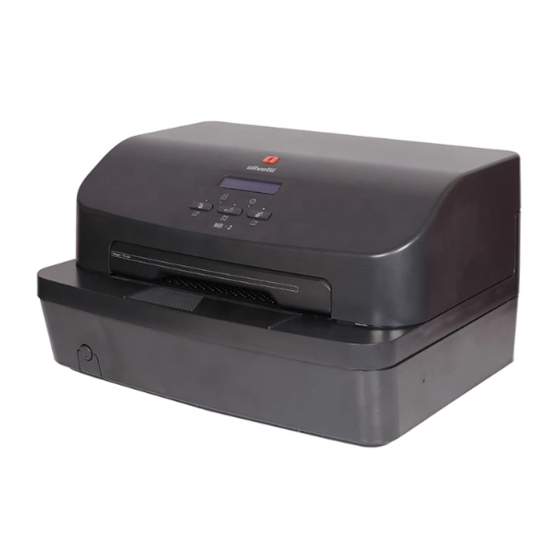
Chapter 1 - OVERVIEW INTRODUCTION The MB-2 is a multifunction printer for the banking environment able to handle documents (both multi-copy and not) and passbooks for deposit/withdrawal transactions. This highly versatile printer can also be used for Public Administration front-office transactions or in Post Offices. -
Page 10: Technical Specifications
Length: 70 mm min x 297 mm min. Located on the printer cover and composed of three keys and five LEDs CONSOLE Optionally an alphanumerical LCD display can be integrated Olivetti standard Standard IBM PP & X24 IBM 4722/9068 EMULATIONS... -
Page 11: Documents That Can Be Handled By The Basic Machine
Width: 384 mm Depth: 296 mm DIMENSIONS Height: 204 mm Weight 10.5 Kg POWER CONSUMPTION During printing: 170 W max (worst performance) 230 Vac + 10% POWER SUPPLY 50/60 Hz DOCUMENTS THAT CAN BE HANDLED BY THE BASIC MACHINE • SINGLE FORM •... -
Page 12: Location Of Main Components
LOCATION OF MAIN COMPONENTS The following figure illustrates the main external components of the printer. Figure 1 - 2 Location of main external components Cover USB interface connector Display Parallel interface connector Console Standard serial interface connector Rear slot Front slot Mains connector cable USB HUB connector (front) USB HUB connectors (2 connectors) -
Page 13: General Block Diagram
GENERAL BLOCK DIAGRAM In the following schema are indicated also the connectors for connecting the peripherals and the motherboard. 1 I F 2 I F JS1 JS2 J9 J10 T P C S 2 M e c h 2 DS39 3 I F T P C S8 T P C S 9... - Page 14 MOTHERBOARD 1 I F 2 I F LS16 CS10 CS11 RS27 CS17 CS18 RS37 CS19 RS38 RS51 RS53 RS52 DS10 RS58 RS59 RS61 RS63 RS65 DS12 DS16 DS13 RS60 RS62 RS64 DS17 DS11 DS14 DS15 T P C S 2 DS20 DS18 RS67...
- Page 15 Parallel interface connector Carriage reset photosensor connector SBI signal connector of the card for MICR Serial interface connector configuration Printhead connector Power unit connector Signal connector for cards for Horizontal Magnetic Printhead connector and MICR configurations Power and signals connector for Horizontal Alignment device photosensors Magnetic and MICR configuration cards Console connector...
-
Page 16: Micr Reader
MICR READER MICR unit interface card - code XYAB1564 - for managing the optional magnetic units can be connected to the motherboard. The MICR (Magnetic Ink Character Reader) technology allows CNC7 / E13B characters printed on cheques to be read. The reader, located inside printer, operates crosswise to the direction of movement of the paper. - Page 17 SCANNER A fast color scanner with a resolution of 600 dpi is included. The scanner features a fixed lower image acquisition element (CIS) and a mobile upper element that moves from the top down when activated. The layout of the two scanners takes into account the fact that it must be possible to activate these at the same time, eliminating optical disturbances (shadow images) that may occur with particular types of paper.
-
Page 18: Alipr2 Power Supply
ALIPR2 POWER SUPPLY On the power unit controller board a fuse is provided to protect the printer from mains peaks and high charges. Figure 1 - 7 Power supply unit Connector pin-out and fuse ratings The signals on the power unit connectors are given in the following. Motherboard Power Supply (Alimentazione piastra base) External Power Supply... - Page 19 CONSOLE The console comprises 3 keys, 5 LEDs and a display. For the meanings of the LEDs and keys, refer to the section “Console keys and LEDs” on page 3 - A magnetic switch (Dry-reed) signals to the motherboard when the upper cover of the printer is opened. MB - 2 Figure 1 - 9 Console Flat cable connector of the console for...
- Page 20 Page left intentionally blank Y112890-3 1-12 Service Manual...