Table of Contents
Advertisement
Quick Links
Advertisement
Table of Contents
Troubleshooting

Related Manuals for Furuno TS-331A


Summary of Contents for Furuno TS-331A
- Page 1 WIRED TRAWL SONAR TS-331A...
- Page 2 Printed in Japan All rights reserved. All rights reserved. Pub. No. OME-13210 Pub. No. OME-13210 ( ( DAMI DAMI ) ) TS-331A TS-331A The paper used in this manual is elemental chlorine free. Your Local Agent/Dealer Your Local Agent/Dealer FIRST EDITION : FIRST EDITION : JAN JAN.
- Page 3 Immediately turn off the power at the switchboard if water leaks into the surface processor unit. Continued use of the equipment can cause fire or electrical shock. Contact a FURUNO agent for service. Install batteries in the catch sensor with correct polarity.
-
Page 4: Table Of Contents
TABLE OF CONTENTS FOREWORD ... iii SYSTEM CONFIGURATION ... iv OPERATIONAL INFORMATION ... v 1. OPERATIONAL OVERVIEW...1 1.1 Surface Processor Unit... 1 1.2 Underwater Unit... 2 1.2.1 Components of the underwater unit ... 2 1.2.2 Trawl system ... 2 1.2.3 Mounting the underwater unit on the trawl... -
Page 5: Foreword
Features The TS-331A is a third wire, head rope mounted system incorporating a high resolution scanning sonar designed especially for monitoring the opening of the trawl net and surrounding areas. Also... -
Page 6: System Configuration
SYSTEM CONFIGURATION Power source 100-240VAC φ , 50-60 Hz SHIPBOARD SECTION UNDERWATER SECTION : Standard supply : Optional supply : Local, user supply PC Monitor (User supply) Surface Processor Unit Keyboard Winch Cable Block Underwater Unit Catch Sensor (option) (4 max.) System configuration Mouse... -
Page 7: Operational Information
OPERATIONAL INFORMATION The following may occur during operation. Follow the recommended procedure to restore normal operation. Cannot restore unit of temperature measurement to Celsius Remedy 1. Choose Load Configuration from the File menu. 2. Find the file Default.cfg in the Imagenex program files and click Open. If Fahrenheit is selected and Save Configuration is executed, the file Default.cfg will be overwritten, which will prevent changing of unit of temperature measurement. - Page 8 This page intentionally left blank.
-
Page 9: Operational Overview
OPERATIONAL OVERVIEW Surface Processor Unit The Surface Processor Unit (sometimes referred to as “Processor”) has a built-in PC mother board, Windows XP least 2GB disk space. The system provides a control and display application TS331A.exe (installed on the Processor), which is a very convenient tool for users to control system parameters such as acoustic operating range, scan speed, scan area, etc. -
Page 10: Underwater Unit
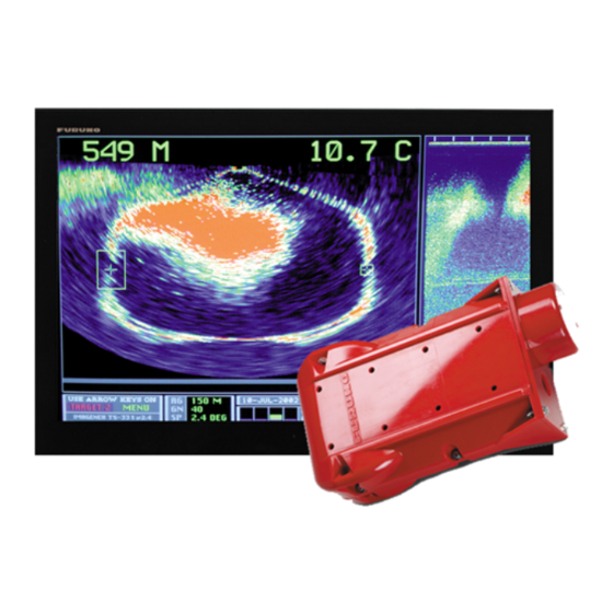
1. OPERATIONAL OVERVIEW Underwater Unit 1.2.1 Components of the underwater unit The underwater unit mainly consists of a red polyurethane case and three transducers. The vertical sonar transducer is the cylindrical red housing which extends from the back of the case. The (gray) echo sounder transducer is mounted near the front of the unit. -
Page 11: Mounting The Underwater Unit On The Trawl
1.2.3 Mounting the underwater unit on the trawl Usually the underwater unit is fixed either on the head rope of the trawl or on the belly just above the ground rope. The advantage of the former position is that the underwater unit is held horizontal almost throughout the towing operation and consequently a good, stable image can be expected. -
Page 12: Starting Up, Shutting Down
1. OPERATIONAL OVERVIEW Starting Up, Shutting Down 1.3.1 Starting up 1. Check the connection between the underwater unit and the winch. 2. Mount the underwater unit on the trawl, referring to paragraph 1.2.3. 3. Shoot the trawl. 4. Turn on the processor unit and the monitor. Adjust display brilliance referring to the owner’s manual of the monitor. -
Page 13: Catch Sensor Cs-400 (Option)
Catch Sensor CS-400 (option) Mounted on the cod end of the trawl, the catch sensor monitors the catch of fish. Four catch sensors may be mounted. The data from each catch sensor is transmitted to the underwater unit via the acoustical link and sent to the Processor. -
Page 14: Screen Layout
1. OPERATIONAL OVERVIEW Screen Layout The fully configured TS-331A provides five viewing windows (Vertical sonar image, Depth/water temperature information, Echo sounder image, Catch sensor information, and Pitch/roll information) plus a Settings dialog box*. * The Vertical Sonar Settings dialog box is initially shown. -
Page 15: Menu Bar
The menu bar is the horizontal strip below the title bar at the top of the screen and it contains the titles of the TS-331A’s drop-down menus. To open a menu, sub menu or choose an option, click it with the left mouse button. A sub menu which has an arrow (►) means it contains an options selection window, such as... - Page 16 1. OPERATIONAL OVERVIEW Tool Main Toolbar Connects to sonar head. Opens an existing .331 data file to play back. Saves real-time acquired sonar data to a .331 file. Stop saving real-time data. Increases operating range by one level. Vertical sonar range: 10, 20, 30, 40, 50, 60, 80, 100, 150, 200, 250 (meters) or equivalent feet/fathoms.
-
Page 17: Display Indications
Trawl Direction: Cod End Tr. Water spd : Pitch:---- CE Water spd : Roll :---- Scale Indications 1. OPERATIONAL OVERVIEW FURUNO logo appears here. Depth Temp. scale scale Settings dialog box Item not available with active window is shown in gray. -
Page 18: Pop-Up Windows
1. OPERATIONAL OVERVIEW Pop-up Windows The TS-331A provides convenient pop-up windows from which to conduct various operations for the vertical sonar window, echo sounder window, depth/temperature window, pitch/roll window and catch sensor window. To activate a pop-up window, place the cursor in the window corresponding to the pop-up menu you want to use and then click the screen with the right mouse button. -
Page 19: Sonar Operation
SONAR OPERATION Choosing a Sonar Mode The TS-331A has three sonar display modes: polar, sector and locked. Choose desired mode from the Mode menu. 2.1.1 Polar mode This mode is used for operating the sonar to scan a 360° area. The transducer location is in the middle of the sonar image display with the zero heading vertically down on the display. -
Page 20: Sector Mode
2. SONAR OPERATION 2.1.2 Sector mode This mode is used for operating the sonar to scan in a sector area. The transducer location is in the middle of the sonar image display with the zero heading vertically down on the display. The user can adjust the scan sector size by selecting the desired sector size from the Sector combo box in the Vertical Sonar settings dialog box. -
Page 21: Locked Mode
2.1.3 Locked mode This mode functions to operate the sonar as an echo sounder, with the transducer locked at 0° sector size. The transducer location is at the top of the sonar image display and the image data is displayed across the screen from right to left. -
Page 22: Adjusting The Sonar Image From The Vertical Sonar Settings Dialog Box
2. SONAR OPERATION Adjusting the Sonar Image from the Vertical Sonar Settings Dialog Box The vertical sonar settings dialog box contains all the controls for adjustment of the sonar image. To display this box if it is not displayed, click the sonar image with the left mouse button and then choose Show Sonar Settings from the View menu. -
Page 23: Adjusting Gain
2.2.2 Adjusting gain Adjust the gain from the Data Gain combo box. The gain range is 0-100(%). Data gain is used to increase or decrease the intensity (color levels) of the vertical sonar and sounder images. 2.2.3 Choosing train angle Select the scan train angle from 0°... -
Page 24: Monitoring Trawl Position
2. SONAR OPERATION Monitoring Trawl Position The Locked mode can be a valuable tool for monitoring trawl location in order to prevent damage to the trawl by shoal or other protrusion. Ground rope If the ground rope is positioned in the coverage area of the sounding beam it is displayed as a line almost parallel with the transmission line. - Page 25 4. The ship has accelerated to clear a shoal. The trawl is rising off the bottom and the bottom is displayed as if it has a sharp undulation though it actually does not. 5. The trawl is passing over the shoal. The ground rope seen off the bottom indicates that the shoal has been cleared.
-
Page 26: Drawing Lines And Symbols
2. SONAR OPERATION Drawing Lines and Symbols Using the draw tool bar or the Draw menu, you can draw lines and symbols on the sonar display (to mark important echoes). This can be done from the Draw menu or with the Draw toolbar. 2.4.1 Drawing a symbol Choose Symbol from the Draw menu or click the... -
Page 27: Choosing Line/Symbol Color
2.4.3 Choosing line/symbol color The default line/symbol color is white. However, you may choose line/symbol color as desired. Choose Line/Symbol Color from the Draw menu, and the dialog box shown below appears. Choose the desired color and then click the OK button. -
Page 28: Finding Range And Bearing From Own Ship To A Point
2. SONAR OPERATION Finding Range and Bearing from Own Ship to a Point Choose Range / Bearing from the Draw menu or click the draw toolbar. Roll the mouse to position the cursor where you want to measure the range and bearing and click the left mouse button. The range and bearing from own ship to the point is shown. -
Page 29: Choosing Display Color
Choosing Display Color You may choose the color arrangement for the vertical sonar image. Open the Color Table menu and check color desired. Color table menu description Normal High: Normal Low: Green: Grey: Reverse Grey: Brown/Yellow: Green/Blue: Green/Yellow: Blue: Color Table menu This scale maps echo data amplitude to 118 colors, ranging from black (low strength) through blue, green, orange, yellow, white and red (highest strength). -
Page 30: Grid
2. SONAR OPERATION Grid You may configure the grid on the vertical sonar display as desired from the Grids menu. Grids menu, Scale Options, Scale Text Size selected Grids menu description Check to display a circular grid. Circular grid: Displays a square grid. Square grid: Check to turn off grid. -
Page 31: Unit Of Depth, Range Measurement
Unit of Depth, Range Measurement The unit of depth/range measurement may be chosen from meters, feet and fathoms, on the Options menu. Check the unit desired. 2.10 Noise Filter You may encounter occasional or intermittent noise and interference on the vertical sonar display or echo sounder display. -
Page 32: Recording Sonar Data
2.12 Playing Back Sonar Data You can also use the TS-331A.exe program to playback data that has been recorded to a file (with file extension .331). To open a .331 data file to playback, select “File->Open File to Playback” or click the Toolbar button frame window will show a File Playback dialog bar. - Page 33 . When the system begins acquiring data from the sonar head, the current data file will be closed. The TS-331A program provides several convenient methods (menu commands, dialog boxes, and toolbar commands) to control the sonar unit’s operations, operating parameters and data display windows.
-
Page 34: Saving, Loading System Configuration
2. SONAR OPERATION 2.13 Saving, Loading System Configuration 2.13.1 Saving system configuration You may save sonar settings, window layouts and sensor status to a configuration file (file extension .cfg). You may then load the settings into the system. This is convenient for setting up the equipment according to fishing ground, targeted fish, etc. -
Page 35: Echo Sounder Operation
ECHO SOUNDER OPERATION Echo Sounder Image The echo sounder image is displayed in the echo sounder window at the right side of the screen. Sonar settings: Range: 30 M, Gain: 70%, Speed: 03', Fish in trawl Ground rope of trawl VERTICAL SONAR IMAGE Mode: Polar, Freq: High Echo Sounder: Range: 50 M,... -
Page 36: Adjusting The Echo Sounder Image From The Sounder Settings Dialog Box
3. ECHO SOUNDER OPERATION Adjusting the Echo Sounder Image from the Sounder Settings Dialog Box The echo sounder settings dialog box contains all the controls for adjustment of the echo sounder image. To display this box, click the echo sounder image with the left mouse button and then choose Show Sonar Settings from the View menu. -
Page 37: Using The Echo Sounder Image To Monitor Trawl Location
Using the Echo Sounder Image to Monitor Trawl Location If the ground rope is positioned in the coverage area of the sounding beam it is displayed as a line almost parallel with the transmission line. If a fish school appears between the transmission line and the ground rope it can be considered to be entering the trawl. -
Page 38: Drawing Lines And Symbols
3. ECHO SOUNDER OPERATION Drawing Lines and Symbols The procedure for drawing lines and symbols on the echo sounder is similar to that for the sonar display. For details, see paragraph 2.4. Grid You may display a line grid on the echo sounder display. Check Line Grid on the Grids menu to display the grid. -
Page 39: Depth/Temperature Display
DEPTH/TEMPERATURE DISPLAY The depth and water temperature display graphs depth and water temperature, from right to left across the screen. This display uses a 3-second interrogation timer to determine when to ask the underwater unit for information. When this timer expires, the current interrogation is completed and the next two interrogations will be for the temperature and depth. -
Page 40: Setting Depth/Temperature Limits
4. DEPTH/TEMPERATURE DISPLAY Setting Depth/Temperature Limits You may set the depth and temperature display limits with Depth/Temp Limits on the Options menu. Set low and high limits with the spin buttons and then click the OK button. Depth/Temperature Offset If the depth and/or temperature readout is incorrect you may enter an offset to correct it(them). -
Page 41: Depth/Temperature Scale Text Size
4. DEPTH/TEMPERATURE DISPLAY Depth/Temperature Scale Text Size You may choose the size of the depth/temperature scale text with DT Scale Text on the Options menu. Options menu, DT Scale Text selected... - Page 42 4. DEPTH/TEMPERATURE DISPLAY This page intentionally left blank.
-
Page 43: Menu Description
Selects a printer and printer connection. Print Setup Use this command to terminate your TS-331A program. System will Exit save your display layout, sonar settings and sensor enable/disable status to default.cfg file. The next time you start the program, the... -
Page 44: View Menu
5. MENU DESCRIPTION View Menu Use this command to clear the image in one of vertical sonar, echo Clear Screen sounder and DT (Depth/Temperature display windows. Which window contents will be cleared depends on which window is active. To activate a window (set it on focus), click on that window. -
Page 45: Communication Menu
Choose desired port from the combo box and click the OK button. Port No use. GPS Data-In No use. Data-Out Sonar Menu Sets TS-331A.exe to Bowscan mode. All sensors are disabled except BowScan vertical sonar. Sets TS-331A.exe to TS-331A mode. All sensors are functional. TS-331A 5. MENU DESCRIPTION... -
Page 46: Options Menu
5. MENU DESCRIPTION Options Menu Color Threshold Roll Correction Roll Angle Display->ON Roll Angle Display->OFF Echo Sounder Beamforming Continuous Rotation 1, 2, 3, 4 The Color Threshold dialog box allows the user to adjust the color table for the echo sounder and vertical sonar windows individually. -
Page 47: Help Menu
TS-331A and various types of reference information. Use this command to display the copyright notice and version number of your copy of TS-331A as well as contact information. 5. MENU DESCRIPTION... - Page 48 5. MENU DESCRIPTION This page intentionally left blank.
-
Page 49: Catch Sensor Operation
Each sensor transmits an acoustic signal with its own fixed frequencies so the system knows which one is installed (received a standby signal) or triggered (received a triggered signal). TS-331A uses number 1 to 4 to distinguish them. 69.75kHz/70.25kHz ±50Hz 72.25kHz/72.75kHz ±50Hz... -
Page 50: Catch Sensor Window
6. CATCH SENSOR OPERATION Catch Sensor relative position (edit boxes) Input the relative length between two catch sensors in meters. Total Length of Cod-End Input the total length of the trawl net in meters. Add (button) Add another catch sensor (maximum of 4) in catch sensor display. Delete (button) Delete one sensor. -
Page 51: Testing For Switch Activation
(via a jumper or submerged) only steps 2 and 3 occur. Catch Sensor Transmission Frequency The transmission frequency of the catch sensor(s) can be changed, by a qualified technician. For further details, contact a FURUNO agent or dealer. 6. CATCH SENSOR OPERATION... -
Page 52: Installing The Batteries And O-Ring
6. CATCH SENSOR OPERATION Installing the Batteries and O-ring The catch sensor is powered by three “D” alkaline batteries and battery life is about 1,000 hours. When the battery voltage is low, the appropriate (yellow) “active indicator” on the catch status indicator does not appear. When this occurs, replace the batteries. - Page 53 3. Pull out the battery cap together with the main housing from the polyurethane housing. Main Housing Main housing and battery cap 4. Unscrew the battery cap from the main housing to access the battery holder. Battery cap separated from main housing 5.
- Page 54 6. CATCH SENSOR OPERATION 8. Use your finger to remove the O-ring from the battery cap. 9. Coat the O-ring seat and the indented area below it with silicone grease. 10. Coat the new O-ring with silicone grease and set it in its seat. 11.
-
Page 55: Maintenance & Troubleshooting
MAINTENANCE & TROUBLESHOOTING General Maintenance This equipment is designed and constructed to provide many years of trouble-free performance when properly operated and maintained. However, no machine can perform to the utmost of its ability without proper maintenance. To maintain good performance, check the following points monthly. •... -
Page 56: Replacement Of Internal Battery
7. MAINTENANCE & TROUBLESHOOTING Replacement of Internal Battery A lithium battery on the Mother Board inside the Surface Processor Unit preserves settings when the power is off. When the voltage of the battery is low, the date and time will be wrong. When this happens, have a qualified technician replace the battery, at your earliest convenience. - Page 57 3. Unscrew the connector and then connect the test cable as shown below. Unscrew connector and then connect test cable. SHIELD CASE < A < BELDEN 8424 or 8404 CABLE+ < B < BLACK CABLE- < C < To Surface Processor Unit How to connect the test cable to the underwater unit 4.
-
Page 58: Troubleshooting
7. MAINTENANCE & TROUBLESHOOTING Troubleshooting The table below provides simple troubleshooting procedures which the operator may follow to restore normal operation. If normal operation cannot be restored, do not attempt to check inside the equipment. There are no user-serviceable parts inside. Refer any repair work to a qualified technician. If…... -
Page 59: Diagnostic Test
Diagnostic Test The diagnostic test, which is mainly for use by service technicians, checks the equipment for proper operation. If you feel something is wrong with the equipment, run the test and report the results to the service technician, to aid in diagnosis. -
Page 60: Diagnostic Test Description
7. MAINTENANCE & TROUBLESHOOTING 7.6.2 Diagnostic test description Header: Sent by the sonar system (wet end) to tell the Processor what kind of data format it sent, IGX for image data and ITX for normal digital data. Data Type: (same as Run-Type) sent by the sonar system (wet end) to tell the processor this set of data is coming from which sensor. -
Page 61: Menu Tree
MENU TREE File Connect to Sonar Head Open File to Playback Record Sonar Data Stop Data Recording Save Configuration Load Configuruation Print Print Preview Print Setup Exit View Default Window Settings Clear Screen Full Screen Zoom Factor (100, 125, 150, 175, 200, 300, 400) Main Menu Main Toolbar Draw Toolbar... - Page 62 APPENDIX Draw Symbol Line Range/Bearing Measure Target Height (no use.) Clear Line Art Stop Drawing Choose Line Symbol Color Mode Polar, Sector, Locked Commu- Choose Sonar Com Port nication GPS Data-In (No use.) Data-Out (No use.) Diag- nostics Vertical Sonar Echo Sounder Catch Sensor Depth...
-
Page 63: Specifications
SPECIFICATIONS OF WIRED TRAWL SONAR TS-331A GENERAL 1.1 Display PC monitor (SXGA), 1280(H)x1024(V) pixels 1.2 Display Mode 1.3 Presentation Color UNDERWATER UNIT 2.1 Operating Depth 2,000 m 2.2 Vertical Scanning Sonar Frequency High or Low Sector size Polar: 360°, Sector: 0° to 180°... - Page 64 This page is intentionally left blank.
-
Page 65: Index
INDEX Battery installation (catch sensor)... 44 Battery replacement ... 48 Catch sensor battery installation... 44 catch sensor dialog box ... 41 description ... 5 LED sequence ... 43 O-ring replacement ... 44 testing for switch activation... 43 transmission frequency... 43 Clear screen ... - Page 66 INDEX Play back speed buttons ... 24 Playing back sonar data file progress bar... 24 play back speed buttons... 24 Polar mode (sonar)... 11 Pop-up windows ... 10 Printing ... 35 Range echo sounder... 28 sonar ... 14 Range and bearing to a point (sonar) ... 20 Recording sonar data ...