Table of Contents
Advertisement
Quick Links
Advertisement
Table of Contents

Related Manuals for Furuno FSV-84


Summary of Contents for Furuno FSV-84
- Page 1 COLOR SCANNING SONAR FSV-84 www.furuno.co.jp...
- Page 2 : +81-(0)798-65-4200 A : SEP 2006 Printed in Japan All rights reserved. B3 : JUN . 21, 2007 Pub. No. IME-13290-B3 *00015742911* *00015742911* (DAMI ) FSV-84 *00015742911* *00015742911* * 0 0 0 1 5 7 4 2 9 1 1 *...
- Page 3 FURUNO will assume no responsibility for High voltage exists inside the equipment, any damage associated with improper and a residual charge remains in capacitors installation.
- Page 4 WARNING CAUTION Maximum speed while the transducer is If a steel tank is installed on a wooden projected or being raised or lowered or FRP vessel, take appropriate is as below, to prevent damage to the measures to prevent electrolytic transducer.
-
Page 5: Table Of Contents
TABLE OF CONTENTS SYSTEM CONFIGURATION ..................iv EQUIPMENT LISTS ....................... vi 1. MOUNTING THE EQUIPMENT................1-1 1.1 Hull Unit ..........................1-1 1.2 Processor Unit ........................1-7 1.3 Monitor Unit (option) ......................1-8 1.4 Control Unit .........................1-11 1.5 Transceiver Unit......................... 1-13 1.6 Attachment Kit (option) ...................... 1-14 1.7 FRP Tank (option) ...................... -
Page 6: System Configuration
SYSTEM CONFIGURATION System with locally supplied monitor CONTROL UNIT FSV-8401 External Monitor External equipment Option CONTROL UNIT AD Converter FSV-8401 AD-100 Speed Log Loudspeaker Current Indicator Speed Log Echo Sounder, Current Indicator, other E/S Interface PROCESOR UNIT VI-1100A FSV-8402 Navigator 1 Net Recorder Navigator 2 VI-1100A... - Page 7 System with FURUNO monitor CONTROL UNIT MONITOR FSV-8401 UNIT FSV-2400 External equipment Option AD Converter CONTROL UNIT AD-100 FSV-8401 Speed Log Loudspeaker Current Indicator Sub Monitor Speed Log Echo Sounder, Current Indicator, other E/S Interface PROCESSOR UNIT VI-1100A FSV-8402 Navigator 1...
-
Page 8: Equipment Lists
EQUIPMENT LISTS Standard supply Name Type Code No. Remarks Control Unit FSV-8401-10 — w/10 m cable FSV-8402-100 — 110 VAC Processor Unit FSV-8402-200 — 220 VAC Transceiver Unit FSV-841A — FSV-8432 — 800 mm stroke w/motion sensor & no dome Hull Unit FSV-8442 —... -
Page 9: Mounting The Equipment
1. MOUNTING THE EQUIPMENT 1.1 Hull Unit Note 1: The raise/lower control box on the hull unit contains a motion sensor. Therefore, never drop the hull unit. Note 2: Handle the transducer carefully. Shock will damage its sensitive components. 1.1.1 Mounting considerations Decide the location of the hull unit through consultation with the dockyard and ship owner. - Page 10 1200 mm 500 mm 500 mm 500 mm Compartment Maintenance space, example sonar compartment Note: After mounting the equipment, be sure to install anti-vibration stays, as shown on page 1-6.
- Page 11 1.1.2 Shortening the retraction tank Shorten the tank as necessary so that the transducer positions well below the keel when it is fully lowered. The following table provides guidelines for shortening the tank. Refer also to the retraction tank installation drawing at the back of this manual. Installation Method Stroke...
- Page 12 1.1.3 Remarks for installation of retraction tank 1. Install, if possible, the tank on the keel where the tank can be most firmly fixed. 2. Install the reinforcement ribs as near as possible to the top of the retraction tank, allowing space for tightening of nuts and bolts.
- Page 13 1.1.4 Installing hull unit on retraction tank After welding the retraction tank and allowing sufficient time for cooling, install the hull unit as follows: 1. Clean the hull unit flange, the O-ring and O-ring groove. Coat them with a slight amount of grease.
- Page 14 1.1.5 Installing stays (anti-vibration measure) Install stays from the top of the hull unit to the ship’s hull. The stays should be angle iron with a size of 75×75×9 mm or more and at least two pieces should be used; one each to ship’s bow and stern directions.
-
Page 15: Processor Unit
1.2 Processor Unit Mounting considerations When choosing a mounting location, keep in mind the following points: • The processor unit must be mounted upright. • Locate the unit out of direct sunlight and away from heat sources because of heat that can build up inside the cabinet. -
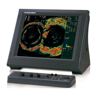
Page 16: Monitor Unit (Option)
Mounting procedure 1. Unfasten two bolts from the bottom of the front side of the processor unit. Pull the unit toward you to separate it from the mounting base. 2. Use six bolts (supplied as installation material) to fix the mounting base. 3. - Page 17 Mounting procedure 1. Drill four holes of 12 mm in diameter in the mounting location, referring to the outline drawing for mounting dimensions. 2. Unfasten two M4×10 screws to dismount the front cover. 3. Unfasten two sets of M10 bolts, plain washers and spring washers to separate the monitor from the mounting base.
- Page 18 Attaching the CRT filter 1. Attach two spacers (5×2.5, supplied) with screws (M5×10, supplied) to the location shown below. 2. Screw two hood retainers (supplied) into the filter (supplied). 3. Set two washers (supplied) into the two hood retainers attached at step 2. 4.
-
Page 19: Control Unit
467±1 Fixing hole φ6 FSV-84 Control unit Mounting with KB fixing plate 1. To fix the control unit to a desired location at an angle, fasten the KB fixing plate to the control unit and desired location with two upset screws (M5×10, supplied) and two... - Page 20 Passing the cable through the bottom of the control unit (for permanent mounting) For permanent mounting methods (2) and (3), the control cable can be passed through the bottom of the control unit as follows: 1. Unfasten eight screws (M4) to remove the cover from the bottom Screw of the control unit.
-
Page 21: Transceiver Unit
1.5 Transceiver Unit The length of the cable between the transceiver unit and the hull unit is 5 m, so choose a mounting location within 5 m of the hull unit. The transceiver unit should be fixed to a mounting base (shipyard supply) whose dimensions are as shown in the outline drawing at the back of this manual. -
Page 22: Attachment Kit (Option)
1.6 Attachment Kit (option) The attachment kit permits use of the tank for the CSH-80 series. Attachment kit (Type: OP10-30, Code no.: 000-067-179) Name Type Code No. Insulation gasket (1) SHG-0003-0 100-038-570 Insulation gasket (2) MS-1000-68 000-857-221 O-ring C00117A 000-158-976-10 1. - Page 23 Hex.nut Hex.nut Spring washer Spring washer Flat washer Flat washer Hull unit flange O ring O ring Insulation gasket (1) Insulation gasket (1) Insulation gasket (2) Insulation gasket (2) Flat washer Flat washer Hex. bolt Hex. bolt Hex. nut Spring washer Flat washer O ring Insulation gasket (1)
-
Page 24: Frp Tank (Option)
1.7 FRP Tank (option) Caution for installing FRP tank Use an FRP tank supplied by FURUNO. Other makes of tank may be used, however watertightness cannot be guaranteed. A non-FURUNO make of tank should meet the following requirements: - The surface of the FRP tank flange must be flush (within 0.5 mm) with tank. - Page 25 4. Set the hull unit on the top of the retraction tank, observing the following cautions: - Clean the hull unit flange to make sure no foreign material has fallen into the retraction tank. - Confirm that the waterproofing gasket is properly in place. Bolt hole 5.
-
Page 26: Control Box Extension Kit (Option)
1.8 Control Box Extension Kit (option) The control box may be mounted separately from the hull unit. Detach the control box and mounting plate from the hull unit and fix the junction box of the control box extension kit to the hull unit, with four M5 bolts MOUNTING PLATE 10-086-5614, 2 pcs. - Page 27 Fix the control box to bulkhead with four M10 bolts. FIXING HOLE TERMINAL TERMINAL CABLE CLAMP 1-19...
- Page 28 This page intentionally left blank. 1-20...
-
Page 29: Wiring
2. WIRING 2.1 How to Use the Crimping Tool, Pin Extractor A special crimping tool is necessary for connection of wires to the contact pins of the 38P connector. The pin extractor removes the contact pin from the connector body. This paragraph describes how to crimp and extract the contact pin. -
Page 30: Wiring
2.2 Wiring Optional supply *1 With monitor unit MONITOR UNIT 10S2076 (10 m) FSV-2400 10S2076 (10 m) FSV-84 *1 No monitor unit CONTROL UNIT FSV-8401 FSV-84 10S2074 (10 m) or 10S2075 (30 m) CONTROL UNIT FSV-8401 Monitor Transceiver (Local supply) - Page 31 Transducer cable If the transducer cable is not quite long enough, unfasten the cable clamp shown in the figure below to release the cable. This will allow a separation of 5 m between the hull unit and transceiver (or junction box). With the cable fastened by the cable clamp, the units may be separated from each other up to 4.5 m.
-
Page 32: Monitor Unit (Option)
2.3 Monitor Unit (option) 2.3.1 Fabrication of cable from processor unit One of the cables 10S2074 (10 m) or 10S2075 (30 m) runs between the processor unit (FSV-8402) and the monitor unit (FSV-2400). Pass it through the cable clamp at the rear of the monitor unit and connect. - Page 33 Positioning guide pins Guide pins of the connector identify the mating receptacle. They are; • Guide pin A (Large): 4 • Guide pin B (Small): 1 Use the tool (Type: 10-910-0179-0) shown below to position guide pins. Connector Tool CN-A303 Guide Pin Guide Pin A (Large) Guide Pin B (Small)
- Page 34 Cable clamp Assembling D-sub connector 2.3.2 Connecting cable between processor unit and monitor unit For the FURUNO-supplied monitor, connect the cable (10S2074 or 1022075) from the processor unit (FSV-8402) to the CN-A302 – CN-A308 connectors on the monitor unit (FSV-2400).
- Page 35 CN-A306 CN-A305 CN-A304 CN-A308 CN-A307 CN-A302 Connector board CN-A301 CN-A303 Cable from processor unit (10S2074 or 10S2075) Cable from control unit (10S2076) Clamp Cable cover Monitor unit, rear view...
-
Page 36: Processor Unit
2.4 Processor Unit Cables from the monitor unit, transceiver unit and other equipment are connected to the CONE Board (10P6905) in the processor unit. Group cables according to left side and right side connection point and bind each group with cable tie, 15 cm from connector. - Page 37 2.4.1 Cable from transceiver unit This cable (10S1258) runs between the processor unit and transceiver unit (FSV-841). Pass it through the cable clamp in the processor unit and connect it to CN-A101 on the CONE Board. Shield Anticorrosive Sheath 1. BLK 9.
- Page 38 Positioning guide pins Guide pins of the connector identify the mating receptacle. They are; • Guide pin A (Large): 1 • Guide pin B (Small): 1 Use the tool (Type: 10-910-0179-0) shown below to position guide pins. Connector Tool CN-A101 Guide Pin Guide Pin A (Large) Guide Pin B (Small)
- Page 39 2.4.5 Optional equipment Optional equipment (navigator, current indicator, AD converter, speed log, etc.) are connected at the rear of the processor unit. Use the SRCN connectors (optionally supplied, Type: CP10-04801, Code no.: 006-934-240) to connect equipment to the rear of the processor unit. Cable list Outline of core Simple...
- Page 40 J5 (CIF1) : SRCN6A13-5P J7 (GYR : SRCN6A16-10P Cable with armor J8 (LOG) : SRCN6A13-3P J10 (FNZ) : SRCN6A21-10P J13 (EXT-KP) : SRCN6A21-10S 8 cm 2 cm 1 cm Armor Shield 3 mm Vinyl sheath Clamp fixing screw Solder unused cores and earth to braided shield.
- Page 41 Synchronizing with echo sounder or other sonar To synchronize the transmission of the FSV-84 with an echo sounder or other type of sonar, make connections as shown below. • Current driven KP input PROCESSOR EXT-KP UNIT KP signal EXT-KP-IN-H Echosounder...
-
Page 42: Transceiver Unit
2.5 Transceiver Unit 2.5.1 Fabrication of 38P connector 00-8016-038-313761HV (CN-B101) Pass the cable (10S2158) from the processor unit (FSV-8402) through the cable clamp on the transceiver unit (FSV-841) and connect it to CN-B101. Anticorrosive Shield Sheath Vinyl Sheath Armor Core Insulating Tape After exposing cores, wind shield around the armor. - Page 43 Power cable fabrication Use power cable DPYCY-2.5 or equivalent. (Power source side: 200) FV2-4 (2 pcs.) Anticorrosive Vinyl sheath Armor sheath Satellite compass cable fabrication Use cable type TTYCS-1Q and connect it to TB B102. Armor Sheath Shield φ = 11.3 mm Braided shield Conductor...
- Page 44 (64 pin) (64 pin) TRX-1 TRX-16 Fix cables by clamps. CN-B101 TB-B10 CN-B102 Fix cables Fasten shield with by clamps. steel clamp. TB-B101 Clamp for transducer cables To Processor Unit (cable 10S1258-1) Cable To Hull Unit Arrange transducer cables as shown above and (cable 10S2078) fix them with clamp.
-
Page 45: Control Box Of Hull Unit
2.6 Control Box of Hull Unit Connect the power cable TYPCY-4 (3φ) and the transceiver unit cable (10S2078, end with shorter peeled portion) as shown below. Sheath Armor M4 (YEL) x 3 FV5.5-4 Vinyl sheath Vinyl sheath Anticorrosiove Conductor Clamp sheath S = 4 mm armor. -
Page 46: Input Voltage And Fuses
2.7 Input Voltage and Fuses The transceiver unit is shipped from the factory with its input voltage set for 230 VAC and a 10 A fuse inserted in F601 and F602. For other voltages, change toggle switch positions and fuses as below. Input voltage Set the toggle switches S603, S604 and S605 according to input voltage, referring to the table below. -
Page 47: Controller Extension Kit (Junction Box)
2.8 Controller Extension Kit (Junction Box) Wire the junction box of the controller extension kit as shown below. Cable from TB-1 in control box Cable from TB-C101 in control box Cable from limit switch in hull unit Cable from motor brake in hull unit 2-19... - Page 48 This page intentionally left blank. 2-20...
-
Page 49: Adjustment And Check
3. ADJUSTMENT AND CHECK 3.1 Hull Unit Check Setting transmission on Default setting of transmission is OFF. Set the transmission on as follows: Note: NEVER transmit when the vessel is in drydock. 1. Turn on the power, and then press the [MENU] key to show the main menu. MENU QUIT TX PULSE LENGTH-H : 9... - Page 50 4. Choose YES and press the [MENU] key. MENU QUIT OTHERS QUIT INITIAL SETTING QUIT MARK DISPLAY... MARK SIZE... DATA DISPLAY... CURRENT VEC & WIND... NET SONDE SETTING... NET SHOOT SETTING... TARGET LOCK... STABILIZATION... TEST... INITIALIZATION... INITIAL SETTING menu 5. Choose TEST and press the [MENU] key. MENU QUIT OTHERS...
- Page 51 3. Remove the cover of the raise/lower control box and use a multimeter to measure the following voltages: Terminal Terminal No. Voltage TB-C101 (1) – (2) 220 VAC (2) – (3) 220 VAC (1) – (3) 220 VAC 4. In the raise/lower control box, set the TEST/NORMAL switch to TEST. Press the [DOWN] switch to confirm that the transducer lowers.
-
Page 52: Heading Adjustment
3.2 Heading Adjustment When the BOW mark on the flange of the hull unit cannot be directed toward ship’s bow, adjust the heading so an echo which is dead ahead appears dead ahead on the display. 1. Referring to the previous section, set the TX (transmission) to ON. 2. - Page 53 MENU QUIT OTHERS QUIT LANGUAGE : English HEADING ADJUST1 0° QUIT HEADING ADJUST2 0° CANCEL PROPELLER DIREC : -180° ES2 SELECT : ES ES DRAFT OFFSET : 0.0m EVENT KEY : EVENT AUTO TILT : NARROW SELECT USER PROG :H/V INTERLOCK TRACKBALL SPEED : NORMAL HULL UNIT STROKE : 1100m OTHERS menu, HEADING ADJUST...
-
Page 54: Configuring Own Ship Mark
3.3 Configuring Own Ship Mark Set own ship’s dimensions and the location of the transducer to accurately display the own ship mark on the display. 1. Press the [MENU] key to display the SYSTEM menu. SYSTEM MENU QUIT INTERFACE SETTING... EXT DATA SETTING... -
Page 55: Other System Menu Items
5. Choose ▲ or ▼ and then operate the [MENU] key to set the ship’s length (15 to 150 m). 6. Choose QUIT to finish the setting. TD Position 1 7. Set the SHIP’S WIDTH (5 to 30 m), TD POSITION 1 (5 to 50 m) or TD POSITION 2 (-10.0 to 10.0 m) similarly. - Page 56 CIF BAUD RATE: Set the transmission rate for the CIF port. If the CS-120A is connected, choose “2400 bps”. (2400 bps, 4800 bps, 9600 bps, 19200 bps) AUX BAUD RATE: Set the transmission rate for the AUX port. (2400 bps, 4800 bps, 9600 bps, 19200 bps) SENSOR BAUD RATE: Set baud rate of satellite compass, connected to the transceiver unit.
- Page 57 SPEED & COURSE: Choose the input format for ship’s speed and course data. When choosing the LOG&HEADING, the heading data is used instead of the course data. (NONE, LOG&HEADING, CIF, NMEA) SPEED SENSOR: Choose the input format for speed and course data. This setting is ineffective when LOG&HEADING is selected as speed and course source.
- Page 58 Data sentences NMEA Input sentences Sentence Main data source Main data Latitude, longitude Latitude, longitude Loran C Latitude, longitude Latitude, longitude, speed Latitude, longitude Time, date Ship speed, tide speed Speed thru water, speed over ground Tide speed Speed thru water True course, speed over ground Tide speed Tide speed and direction...
-
Page 59: Others Menu
3.4.3 OTHERS menu MENU QUIT OTHERS QUIT LANGUAGE : English HEADING ADJUST1 HEADING ADJUST2 PROPELLER DIREC : -180 ES2 SELECT : ES ES DRAFT OFFSET : 0.0m EVENT KEY : EVENT AUTO TILT : NARROW SELECT USER PROG :H/V INTERLOCK TRACKBALL SPEED : NORMAL HULL UNIT STROKE : 800m TD TYPE... -
Page 60: Cone Board Setting In The Processor Unit
2. For ES1, adjust R168 to suppress noise, and then adjust R209 so that the picture condition is similar to that of connected echo sounder connected to the FSV-84. 3. For ES 2, adjust R119 to suppress noise, and then adjust R167 so that the picture condition is similar to that of echo sounder connected to the FSV-84. -
Page 61: Dip Switch Setting
3.6 DIP Switch Setting J496, J497 DCON board (10P6987) IFES board (10P6903) I F E A L D Processor unit, inside view 3.6.1 CIF2/NMEA2 connector interface selection The signal format for the CIF2/NMEA2 port (at the back of the processor unit) can be set for CIF or NMEA by DIP switch S2-8 on the IFES Board (10P6903). - Page 62 ES2/NET J497 Note: The SIGOUT (AC signal) terminal and REC terminal (DC signal) in the output port are provided for a FURUNO echosounder. Therefore, when using the SIGOUT terminal, it is not necessary to change the above-mentioned jumper setting. 3-14...
-
Page 63: Connecting External Interface Cs-120A
4. CONNECTING EXTERNAL INTERFACE CS-120A The External Interface CS-120A functions to enable upgrading from a past CSH series sonar. However, we recommend that you connect external devices directly to the processor unit, to avoid signal delay. Connect echo sounder and net sonde directly to the processor unit. Install the following power supply kit (option) in the processor unit to enable use of the CS-120A. - Page 64 3. Fix the power supply pcb (supplied) to the power module with four spacers (supplied). 4. Connect two VH connectors (provided on the power module) to the power supply pcb. 5. Lay the protection sheet (supplied) on top of the spacers and fasten with pan head screws (M3×8).
- Page 86 D-10...
- Page 87 D-11...
- Page 88 D-12...
- Page 89 D-13...
- Page 90 D-14...
- Page 91 D-15...
-
Page 92: Interconnection Diagrams
Mar. 20 '07 *3: CONNECTOR PLUGS FITTED AT FACTORY. APPROVED *3)コネクタは工場にて取付済み。 相互結線図 *4: 00-8016-038-313761HVF *4)00-8016-038-313761HVF MASS SCALE NAME COLOR SCANNING SONAR *5)( ):副表示部用。 *5: ( ): FOR SUB MONITOR UNIT. DWG No. INTERCONNECTION DIAGRAM C1329-C01- D FURUNO ELECTRIC CO., LTD. - Page 93 送受波器 振動子ケーブル延長キット 送受信装置 制御部 TRANSDUCER TRANSDUCER CABLE EXTENSION KIT DS1V-B TRANSCEIVER UNIT PROCESSOR UNIT FSV-8422/8423 FSV-841A(FSV-84) FSV-8402 距離:5m標準(FSV-84) DS1VSY FSV-841B(FSV-84L) DISTANCE: MAX.5m FOR FSV-84 (延長キット使用で最大20m) CN-B103 DS1HSY (FSV-84Lのみ) TD-H TD-C DATA_OUT1-5 TTYCS-1 TD-A サテライトコンパス RD-H TD-B SATELLITE COMPASS RD-C SC-50/110...
- Page 95 PCS-E68PM PC IF MONITOR KEC-15P データ収録装置 外部モニター MD-R DATA RECORDER 制御部 EXTERNAL MONITOR メンテナンス専用 PROCESSOR UNIT MD-G FOR MAINTENANCE FSV-2402/2402S MD-B FSV-3002/3002S FSV-8402 MD-V-SYNC SRCN6A16-10P ES2/NET 魚探 I/F 02S8040,6m ES2-SIG-IN MD-H-SYNC ES I/F VI-1100A KP-DN-IN NMEA1 MJ-A6SPF MJ-A6SPF0011/0012 航法装置 ES2-WL-IN NMEA1-TXD-H 5/10m,φ6 NAVIGATOR...