Table of Contents
Advertisement
Advertisement
Table of Contents

Related Manuals for Furuno NX-300


Summary of Contents for Furuno NX-300
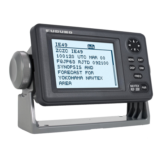
- Page 1 OPERATOR'S MANUAL NAVTEX RECEIVER NX-300 MODEL...
- Page 2 Nishinomiya, 662-8580, JAPAN Telephone : +81-(0)798-65-2111 : +81-(0)798-65-4200 Printed in Japan All rights reserved. Pub. No. OME-56290-J4 (YOTA ) NX-300 The paper used in this manual is elemental chlorine free. ・FURUNO Authorized Distributor/Dealer A : MAR J4 : SEP . 02, 2010...
- Page 3 (http://www.eiae.org/) for the correct method of disposal. How to discard a used battery Some FURUNO products have a battery(ies). To see if your product has a battery, see the chapter on Maintenance. Follow the instructions below if a battery is used. Tape the + and - terminals of battery before disposal to prevent fire, heat generation caused by short circuit.
- Page 4 SAFETY INSTRUCTIONS Safety Instructions for the Operator WARNING Do not open the cover of the equipment. Only qualified personnel should work inside the equipment. Immediately turn off the power at the ship's mains switchboard if water or foreign object falls into the equipment or the equipment is emitting smoke or fire.
- Page 5 The voltage rating appears on the label at the rear of the equipment. Observe the following compass safe distances to prevent interference to a magnetic compass: Standard Steering compass compass 0.5 m 0.3 m NX-300...
-
Page 6: Table Of Contents
FOREWORD ... vi A Word to NX-300 Owners ... vi Features ... vii SYSTEM CONFIGURATION ... viii EQUIPMENT LISTS... ix 1. PRINCIPLE OF NAVTEX SYSTEM...1-1 1.1 How NAVTEX Works ...1-1 1.2 NAVTEX System Operation...1-1 1.3 Message Format...1-2 1.4 Display Indications...1-3 1.5 NAVTEX Station Map ...1-4... - Page 7 3.5 Delete All Messages ...3-4 3.6 User Display of Navigation Data...3-4 4. OTHER FUNCTIONS...4-1 4.1 DEMO Mode...4-1 4.2 VIEW Mode ...4-1 4.3 All Clear ...4-1 4.4 Changing Received Message Log Window ...4-2 5. MAINTENANCE & TROUBLESHOOTING ...5-1 5.1 Maintenance ...5-1 5.2 Diagnostic Test ...5-1 5.3 When the Battery Icon Appears...5-2 5.4 Replacement of Fuse ...5-3...
-
Page 8: Foreword
Our extensive global network of agents and dealers furthers this dedication to excellence. The NX-300 is just one of the many FURUNO developments in the field of marine radio communication. The NX-300 provides cost-effective price, high sensitivity and simple operation in one compact and light-weight unit. -
Page 9: Features
The service range of a NAVTEX station is typically 200-400 nautical miles. A NAVTEX station normally broadcasts every 4 hours. The NAVTEX message is relevant for all types and sizes of vessels. The NX-300 is shipped from the factory equipped to receive 7 specific types of NAVTEX messages from all NAVTEX stations. -
Page 10: System Configuration
Antenna Cable (10 m) FURUNO viii SYSTEM CONFIGURATION H-field ANTENNA UNIT NX-3H-D NAVTEX RECEIVER NX-300-D MENU DISP FREQ Power Cable (2 m) 12-24 VDC NX-300 System configuration GPS navigator Personal Computer... -
Page 11: Equipment Lists
Standard supply Name Type NAVTEX Reveiver NX-300-D Antenna Unit NX-3H-D Installation Materials Spare Parts Accessories Optional equipment Name Right Angle Antenna Base L-type Antenna Base Handrail Antenna Base Mast Mount Kit Flush Mount Kit S Flush Mount Kit F EQUIPMENT LISTS... - Page 12 This page intentionally left blank.
-
Page 13: Principle Of Navtex System
1. PRINCIPLE OF NAVTEX SYSTEM How NAVTEX Works There are many types of navigational and meteorological information available on radio, such as NAVAREA, HYDROPAC, etc. However, these systems rely heavily upon the operator's experience and skill in tuning the radio and interpreting messages. In addition, constant monitoring to pick up wanted information among a vast volume of messages is not practical with a limited radio staff. -
Page 14: Message Format
1.3 Message Format For automatic identification of messages, each message starts with eight control characters, called "Header codes". The first four characters are always "ZCZC" and common to all messages. This part is used for message synchronization. The latter four characters are designated as b1, b2, b3 and b4 to indicate origin, category and serial number of the message. -
Page 15: Display Indications
Display Indications SAR: Displayed when message type D is displayed. WARNING: Appears when message type A, B or L is displayed. Figure 1-2 Display indications NEW: Displayed when message is displayed for the first time. WARNING receiving: Lights (and the alarm sounds) when message type A, B or L is received. -
Page 16: Navtex Station Map
NAVTEX Station Map... -
Page 17: Navtex Station List
NAVTEX Station List Country Station area Belgium Oostende Estonia Tallinn Iceland Reykjavik Radio Ireland Valencia Malin Head France Niton Netherlands Coast Netherlands Guard Norway Bodo Radio Rogaland Radio Vardoe Radio Svalbard Ørlandet Sweden Harnosand Karlskrona Stockholm Radio Gothenburg (Grimeton) United Cullercoats Kingdom Portpatrick... - Page 18 Country Station area Spain Tarifa Las Palmas Bulgaria Varna Croatia Split Cyprus Cyprus Egypt Alexandria Serapeum France Cross La Garde Greece Heraklion Corfu Lemnos Israel Haifa Italy Roma Augusta Cagliari Trieste Malta Malta Russian Novorossiysk Federation Astrakhan Spain Cabo de la Nao Turkey Istanbul Samsun...
- Page 19 Country Station area Canada Montreal Labrador Iqaluit, NU Denmark (Greenland-We Godthaab(Nuuk) st Coast) United States Miami Boston New Orleans Chesapeake San Juan Savannah, GA Netherlands Curacao Antilles Uruguay Colonia Laguna del Sauce La Paloma Montevideo Punta del Este Salto Argentina Ushaia Rio Gallegos Comodoro...
- Page 20 Country Station area Bahrain Hamala Serapeum Egypt (Ismailia) Quseir Iran Bushehr Bandar Abbas Saudi Arabia Jeddah Oman Muscat Pakistan Karachi China Sanya Guangzhou Fuzhou Shanghai Dalian Indonesia Jayapura Ambon Makassar Jakarta Japan Otaru Kushiro Yokohama Moji Naha Korea, Chukpyun Republic of Pyonsan Malaysia Penang...
- Page 21 Country Station area Vietnam Ho Chi Minh City Haiphong Danang Taiwan Chilung Kaohsiung (Linyüan) Associate Member of Hong Kong Canada Prince Rupert Tofino United States San Francisco Kodiak Honolulu Cambria Astoria Adak Russian XIII Kholmsk Federation Murmansk Arkhangelsk Astrakhan Chile Antofagasta Valparaiso Talcahuano...
- Page 22 This page is intentionally left blank.
-
Page 23: Operation
2.1 Control Description All operation of the NX-300 is carried out with the controls on the front panel of the display unit. FURUNO MENU DISP Removing the hard cover To remove the hard cover, squeeze it at its top and bottom right (or left) corners and pull it toward you. -
Page 24: Adjusting Dimmer And Contrast
2.4 Menu Operation Overview The menu allows you to custom tailor the NX-300 according to your needs. You can select which categories of message you wish to receive, specify which data to display, etc. -
Page 25: Selecting Stations
4. Press ! or " to select menu item and press the [ENT] key. For example, select RCV ALARM. Corresponding option menu appears. 5. Press ! or " to select option desired. 6. Press the [ENT] key to resister your selection. 7 Press the [MENU] key once to return to the menu or twice to quit the menu. -
Page 26: Selecting Messages
Press ! or " to select RECEIVE or IGNORE depending on whether you want to select or deselect the station. Press the [ENT] key. Repeat steps b) to e) to select or deselect other stations. Press the [MENU] key or [DISP] key to close the STATION SELECTION menu. Selecting Messages Press the [MENU] key to open the main menu. -
Page 27: Setting Functions (Functions Menu)
(Total number of characters includes space, line feed, carriage returns, etc.) When the character error rate is within the percentage you set (0-39%), the NX-300 displays the message and stores it. When it exceeds the percentage you set, the NX-300 neither displays nor stores the message. - Page 28 SCROLLING: This menu item lets you select how to scroll the message display. The default setting is AUTO-SLOW. AUTO-SLOW: Long press of ! or " scrolls line-by-line slowly automatically. Touch and release " to scroll manually. AUTO-FAST: Long press of ! or " scrolls line-by-line automatically, faster than AUTO- SLOW.
- Page 29 Set up the computer to receive data. Messages are downloaded to a PC character by character during reception. To download all messages saved in NX-300, do the following; Press the [MENU] key to open the main menu. Press ! or " to select FUNCTIONS.
- Page 30 Note1: No message is received during downloading. Note2: When a PC or a serial printer is connected to the NX-300, received messages are displayed on a PC or printed on a serial printer but not displayed or saved to the NX-300 in the following cases;...
-
Page 31: Selecting Language
2.9 Displaying Messages The NX-300 automatically saves and stores up to 132 received messages (However, the memory capacity is limited to 28,000 characters). If memory of the NX-300 is full, messages are deleted on order of time. 1. Press the [DISP] key to show the received messages log. Messages (numbers) are arranged in the order received from latest to earliest, Left to right. -
Page 32: Sample Messages
2.10 Sample Messages When message is displayed, press ! or " to scroll message and press # or $ to display the other message. When the oldest or newest message is displayed, the beep sounds. ID no. Start code (sync) Main message Main message Termination code... -
Page 33: Displaying Navigation Data
2.11 Displaying Navigation Data With navigation data input the NX-300 can display navigation data, in addition to its primary function. 1. Press the [DISP] key to display the receiving messages log. 2. Press the [DISP] key again to display navigation data. -
Page 34: Selecting Receive Frequency
2.12 Selecting Receive Frequency 1. Press the [FREQ] key to show the frequency window. (Default setting is 518 kHz) Figure 2-24 Frequency window 2. Press to select receive frequency as appropriate. 3. Press the [ENT] key to close the frequency window. 2-12... -
Page 35: System Menu
Units of Measurement When navigational data is fed to the NX-300, you can select units of distance and speed to use. Distance/speed can be displayed in nautical miles/knots, kilometers/kilometers per hour, or miles/ miles per hour. The default setting is nautical miles/knots. -
Page 36: Time Difference (Using Local Time)
Time Difference (using local time) GPS uses UTC time. If a GPS receiver feeds nav data to the NX-300 and you would rather use local time, enter the time difference (range: -13:30 to +13:30) between local time and UTC time. -
Page 37: Time Display
3.3 Time Display When navigational data is fed to the NX-300, you may display the time in 12-hour or 24-hour notation. The default setting is 24-hour notation. AM or PM is shown when 12-hour notation is selected. Press the [MENU] key to open the main menu. -
Page 38: Delete All Messages
Press the [MENU] key or [DISP] key to close the SYSTEM MENU. User Display of Navigation Data The NX-300 can function as nav data display when connected to navigation equipment. You may choose what data to display in the three cells below the date and time indications on the nav data display. - Page 39 Press the [ENT] key to show the USER DISPLAY menu. The cursor is now on the LARGE field. LARGE means the center indication on the nav data display. Press the [ENT] key. The following window appears. Operate the Omnipad to select item desired. (SPD: Speed, CSE: Course, RNG: Range to destination, BRG: Bearing to destination, PWR: Power source voltage, L/L: position in latitude and longitude) Press the [ENT] key.
- Page 40 This page is intentionally left blank.
-
Page 41: Other Functions
To quit the VIEW mode,: repeat above procedure. “RESET VIEW MODE!” appears. 4.3 All Clear This function deletes all messages and restores default settings. When the NX-300 is first installed, you should clear all data. Press the [PWR] key while pressing momentarily while data is being cleared. -
Page 42: Changing Received Message Log Window
4.4 Changing Received Message Log Window You can show received frequency on the received message log as shown below. 1. Press the [PWR] key while pressing !to turn the power on and release the keys after display appears. 2. Press the [DISP] key to show the received message log. The received frequencies (518 kHz and 490 kHz) are displayed on the window. -
Page 43: Maintenance & Troubleshooting
Do not open the equipment. Only qualified personnel should work inside the equipment. Further, watertightness may be reduced. Maintenance Check the following points regularly to maintain performance: Check that connectors on the rear panel are firmly tightened and free of rust. Check that the ground system is free of rust and the ground wire is tightly fastened. -
Page 44: When The Battery Icon Appears
Press the [ENT] key to start the test. The equipment checks ROM, RAM, SIO and internal battery, and the results are individually displayed as OK or NG (No Good). Program numbers appear at the bottom of the display. If any NG is displayed, contact your dealer. Note 1: SIO requires a special connector to check. -
Page 45: Replacement Of Fuse
If the fuse blows find out the cause before replacing it. If the fuse blows again after replacement, contact a FURUNO agent or dealer for advice. Use only a 1 A fuse – use of a different fuse will damage the equipment and void the warranty. - Page 46 This page is intentionally left blank.
-
Page 47: Installation
Installation of Display Unit Mounting considerations The display unit can be installed on a tabletop, on the overhead, or in a panel (optional flush mounting kit required). Refer to the outline drawings at the end of this manual for installation instructions. -
Page 48: Installation Of Antenna Unit
6.2 Installation of Antenna Unit Mounting considerations Install the antenna unit referring to the antenna installation diagram at the end of this manual. When selecting a mounting location for the antenna unit, keep in mind the following points: • Do not shorten the antenna cable (10 m cable fitted to the antenna). •... -
Page 49: Wiring
6.3 Wiring The figure below shows where to connect cables on the rear of the display unit. ANTENNA UNIT NX-3H-D NAVTEX RECEIVER 10 m POWER Ground (12-24 VDC) 1 A FUSE (+ Line) Black To personal computer To navigational equipment Figure 6-3 Wiring Note: The fuse holder contains a spring that fixes the fuse. -
Page 50: Interfacing
GPS navigator GP-31/GP-36 for display on its screen. If you want to connect equipment which outputs data in a format other than RS-232C, a level converter is required for interface. Consult FURUNO dealer for details. Input data sentence description... -
Page 51: Menu Tree
MENU STATION SELECTION MESSAGE SELECTION ( A-E, L, V: RECEIVE; OTHERS: IGNORE ) Default settings in boldface italic. FUNCTIONS SYSTEM MENU USER DISPLAY LANGUAGE( ENG , GER, SPA, DEN, FRA, ITA, DUT, POR) MENU TREE MODE ( AUTO , MANUAL) RCV NOTIFY ( OFF , ON) RCV ALARM (OFF, ON ) KEY BEEP (OFF, ON ) -
Page 52: Specifications
Message Selection Mode, NAV Data Mode, Message Display Mode Message Storage ANTENNA UNIT Selectable Antenna NX-3H-D: H-field antenna for NX-300-H-D Others: Local supply antenna for NX-300-N-D Input Impedance Power supply INTERFACE Input Data NMEA0183 Ver.1.5/2.0, RS-232C, 4800 bps GGA, GLL, RMB, ZDA... - Page 53 Maximum acceleration 7 m/s COATING COLOR Navtex receiver Chassis: 2.5GY5/1.5, Panel: N3.0 Antenna Unit 12-24 VDC: 180-90 mA Antenna unit: -25°C to +70°C Antenna unit: IEC-IPX6 , 13.2 to 100 Hz (IEC 60945) N9.5 SP - 2 NX-300 E5629S01D 040324...
- Page 54 This page is intentionally left blank.
-
Page 55: Packing List
PACKING LIST NX-300-H-D N A M E ユニット UNIT 空中線部 ANTENNA UNIT ナブテックス受信機 NAVTEX RECEIVER 予備品 SPARE PARTS ヒューズ FUSE GLASS TUBE TYPE 付属品 ACCESSORIES 保護カバー COVER 工事材料 INSTALLATION MATERIALS ケーブル組品MJ CABLE ASSY. +トラスタッピンネジ 1シュ SELF-TAPPING SCREW 図書 DOCUMENT コーションシート(英) CAUTION SHEET (EN) 取扱説明書(英)... - Page 56 PACKING LIST NX-300-N-D N A M E ユニット UNIT ナブテックス受信機 NAVTEX RECEIVER 予備品 SPARE PARTS ヒューズ FUSE GLASS TUBE TYPE 付属品 ACCESSORIES 保護カバー COVER 工事材料 INSTALLATION MATERIALS ケーブル組品MJ CABLE ASSY. +トラスタッピンネジ 1シュ SELF-TAPPING SCREW 図書 DOCUMENT コーションシート(英) CAUTION SHEET (EN) 取扱説明書(英) OPERATOR'S MANUAL 型式/コード番号が2段の場合、下段より上段に代わる過渡期品であり、どちらかが入っています。 なお、品質は変わりません。...
- Page 60 D - 4...
- Page 62 This page is intentionally left blank.
-
Page 63: Index
All clear 4-1 AUTO 1-3 AUTO mode 2-3 AUTO-FAST 2-6 AUTO-SLOW 2-6 BATTERY icon 1-3, 5-2 Contrast 2-2 Control panel 2-1 Data sentence 6-4 Default setting 3-3 Deleting all messages 3-4 DEMO mode 4-1 Dimmer 2-2 ERROR RATE 2-5 FUNCTIONS menu 2-5 Grounding 6-4 Installation 6-1 KEY BEEP 2-5... - Page 64 SAR 1-3 Saving to PC 2-6 Scroll bar 1-3 SCROLLING 2-6 SKIP-$$ 2-6 Start code 1-2 Station list 1-5 Station map 1-4 Station selection 2-3 SYSTEM MENU 3-1 Termination code 1-2 TEST 5-1 TIME DIFF 3-2 Time difference 3-2 TIME DISP 3-3 Type of message 1-2 Units of measurement 3-1 User display 3-4...