Table of Contents
Advertisement
Quick Links
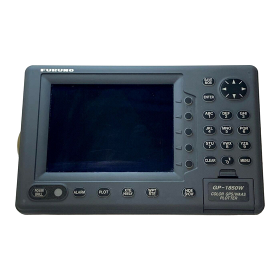
COLOR DGPS/PLOTTER GP-1850WD
COLOR GPS PLOTTER GP-1850W
SYSTEM CONFIGURATION.................................................................................. i
EQUIPMENT LISTS .............................................................................................. ii
1. INSTALLATION ................................................................................................. 1
1.1 Installation of Display Unit ...............................................................................................1
1.2 Installation of Antenna Unit.............................................................................................. 4
2. WIRING ............................................................................................................. 5
3. INITIAL SETTINGS ........................................................................................... 9
3.1 NMEA Setting.................................................................................................................. 9
3.2 Output Data Sentences ................................................................................................. 11
3.3 Antenna Height.............................................................................................................. 12
3.4 DGPS Setting................................................................................................................ 13
(for GP-1850W) ............................................................................................... 15
PACKING LISTS ............................................................................................... A-1
OUTLINE DRAWINGS ...................................................................................... D-1
INTERCONNECTION DIAGRAM ......................................................................S-1
INSTALLATION MANUAL
Back
Advertisement
Table of Contents

Related Manuals for Furuno GP-1850W


Summary of Contents for Furuno GP-1850W
-
Page 1: Table Of Contents
COLOR DGPS/PLOTTER GP-1850WD COLOR GPS PLOTTER GP-1850W SAFETY INSTRUCTIONS SYSTEM CONFIGURATION... i EQUIPMENT LISTS ... ii 1. INSTALLATION ... 1 1.1 Installation of Display Unit ...1 1.2 Installation of Antenna Unit... 4 2. WIRING ... 5 3. INITIAL SETTINGS ... 9 3.1 NMEA Setting... -
Page 3: Safety Instructions
SAFETY INSTRUCTIONS Safety Instructions for the Installer WARNING Do not work inside the equipment unless totally familiar with electrical circuits. Hazardous voltage which can shock, burn or cause serious injury exists inside the equip- ment. Turn off the power at the mains switchboard before beginning the installation. - Page 4 This page is intentionally left blank.
-
Page 5: System Configuration
SYSTEM CONFIGURATION The GP-1850W/1850WD mainly consists of a display unit and a GPS antenna. A DGPS beacon receiver is provided inside the display unit for GP-1850WD type. The mini chart card drive in the display unit loads electronic charts. External equipment which may be connected include an autopilot and a DGPS beacon receiver (GP-1850W). -
Page 6: Equipment Lists
Code No. 000-041-650 000-041-653 000-133-670 004-372-110 004-372-120 000-136-730-01 004-365-780 000-803-239 000-803-240 000-806-114 Remarks for GP-1850W for GP-1850WD Fuse Power cable, cable assy. FP14-02401, FP14-02403 Remarks GPA-019, GR-7000A GPA-019S, GR-7000A 15 m, for antenna cable extension 8D-FB-CV *30M* and CP20-01701, for antenna... - Page 7 Optional equipment (con’t) Name Rectifier PR-62 MJ-A6SPF0011-050 MJ-A6SPF0011-100 Cable Assy. MJ-A6SPF0012-050 MJ-A6SPF0012-100 Remote controller RMC-185-E RAM Card 00RAM02MC-004 C-MAP 1650/1850-MAP modification kit Type Code No. 000-013-484 000-013-485 000-013-486 000-013-487 000-132-244 000-132-336 000-134-424 000-133-817 004-375-300 004-371-790 004-376-420 EQUIPMENT LISTS Remarks for 100 VAC for 110 VAC for 220 VAC for 230 VAC...
- Page 8 EQUIPMENT LISTS This page is intentionally left blank.
-
Page 9: Installation
INSTALLATION Installation of Display Unit Mounting considerations The display unit can be installed on a tabletop, on the overhead or flush mounted in a console or panel. Hard Cover Tabletop, overhead mounting methods When selecting a mounting location for the display unit keep the following in mind: Keep the display unit out of direct sunlight. - Page 10 1. INSTALLATION Rubber foot which absorb vibration (supplied) maybe attached as below if vibration is a problem. 45 5mm Aline with edge of hanger. Mounting procedure Follow the procedure below to mount the display unit on a tabletop or the overhead. Tabletop, overhead mounting 1.
- Page 11 Flush mounting Note: Use supplied pan head screws when the thickness of the bulkhead is from 11 to 14 mm. For bulkhead which exceeds 14 mm in thickness the length of the pan head screws should be bulkhead thickness plus 7.3±1.5 mm. Also the length of B should max.
-
Page 12: Installation Of Antenna Unit
1. INSTALLATION Installation of Antenna Unit Mounting considerations Install the antenna unit referring to the installation diagram on page D-3 or D-4. When selecting a mounting location for the antenna unit, keep in mind the following points: Select a location out of the radar beam. The radar beam will obstruct or prevent reception of the GPS satellite signal. -
Page 13: Wiring
VDC); white to plus(+) terminal and black to minus(-) terminal. Cable connector Connecting the power cable to the battery Display unit TEMP/SPD DGPS External equipment DGPS beacon receiver (option for GP-1850W, Black RS-232C only) Display unit, rear view Power cable w/fuse (5A) Lead wire Black White... -
Page 14: Antenna Unit
2. WIRING Antenna unit Connect the antenna cable to the ANT connector. Ground The display unit contains several CPUs. While they are operating, they radiate noise, which can interfere with radio equipment. Ground the unit to prevent interference. The grounding wire should be 1.25 sq or larger and as short as possible. - Page 15 Extension cable line-up (in case of 15 m, 30 m or 50 m) Fabricate the end of the antenna cable and attach the coaxial connector. Details are shown on the page 8. Antenna unit GPA-019S/017S Cable extension (CP20-01700, CP20-01710) Antenna unit GPA-019S/GPA-017S Waterproofing connector Wrap connector with vulcanizing tape and then vinyl tape.
- Page 16 2. WIRING How to attach the N-P-8DFB connector Dimensions in millimeters. Outer sheath Armor Inner sheath shield Cover with heat-shrink tubing and heat. Clamp Gasket (reddish brown) Trim shield here. Insulator Trim aluminum tape foil here. Clamp nut Solder through the hole.
-
Page 17: Initial Settings
INITIAL SETTINGS NMEA Setting NMEA port This setting should be done when connecting with other equipment, autopilot, radar or remote display. 1. Press the [MENU] key. 2. Press the CONFIGURATION soft key. 3. Press the SETUP NMEA PORT1 soft key. 4. - Page 18 3. INITIAL SETTINGS DGPS port Set the following when connecting with DGPS beacon receiver GR-80 or the DGPS beacon receiver is incorporated, PC to the DGPS port. Note: Signal level for DGPS port is RS232C. 1. Press the [MENU] key. 2.
-
Page 19: Output Data Sentences
Output Data Sentences Select output data sentences for external equipment as follows. 1. Press the [MENU] key. 2. Press the CONFIGURATION soft key. 3. Press the SETUP NMEA PORT1 soft key. 4. Press the SELECT SNTNC. soft key to display the SELECT SENTENCE window. DGPS 3D 5. -
Page 20: Antenna Height
3. INITIAL SETTINGS Input/Output data sentences Port Format Input NMEA-0183 Ver. 2.0 NMEA Ver. 1.5 Output IEC1162 Input NMEA-0183 Ver. 2.0 DGPS Ver. 1.5 RS232C Output RTCM104 *1: Cannot be input consecutively. *2: Output automatically when LC or LA is selected. Antenna Height Enter height of antenna above water. -
Page 21: Dgps Setting
AUTO: DGPS, WAAS or GPS data can be automatically received, The order of priority is DGPS, WAAS and GPS. Note: If the external DGPS beacon receiver GR-80 is connected to the GP-1850W, refer to the interconnection diagram below. Connection with GR-80... - Page 22 3. INITIAL SETTINGS 6. Select BEACON FREQUENCY by the cursor pad. 7. Press the EDIT soft key to display the following message. 8. Select AUTO or MANUAL by the cursor pad. When you select MANUAL, operate the cursor pad to move the cursor to frequency dialog box. And press the cursor pad to select the frequency desired.
-
Page 23: Incorporation Of Dgps Beacon Receiver Kit (For Gp-1850W)
INCORPORATION OF DGPS BEACON RECEIVER KIT (for GP-1850W) The DGPS beacon receiver GR-7000A can be incorporated in the GP-1850W to provide it with DGPS capability. Two kinds of kit are available as shown. GR-7000A-1650-10N-019 Name Type Antenna Unit GPA-019 Beacon... - Page 24 4. INCORPORATION OF DGPS BEACON RECEIVER KIT (for GP-1850W) Disassembly Procedure 1. Turn off the power. Wait at least one minute before opening the cover, to allow capacitors to discharge. 2. Remove nuts attached to DGPS, NMEA and power supply connectors at the rear of the display unit.
- Page 25 4. INCORPORATION OF DGPS BEACON RECEIVER KIT (for GP-1850W) Installation of beacon receiver Procedure 1. Dismount chassis assembly from panel/chassis assembly by disconnecting the connector and PH8P from J8 on MAIN Board shown in the figure below. Remove two ties (CV-100).
- Page 26 4. INCORPORATION OF DGPS BEACON RECEIVER KIT (for GP-1850W) Do not touch the connector with bare hands; use gloves. Use radio pincers to remove, and pull out straightly. Plug in connector straightly. 3. Fasten the GR-7000A (DGPS beacon receiver) to the heat sink with four 3X8 screws as shown in the figure below.
- Page 27 4. INCORPORATION OF DGPS BEACON RECEIVER KIT (for GP-1850W) 5. Close the cover of GR-7000A passing the two cables out through respective notches in the cover. 6. Plug PH6P-W-L240 connector to J2 on the GR-7000A through the cover. 7. Wire cable assembly as shown in the figure below.
- Page 28 4. INCORPORATION OF DGPS BEACON RECEIVER KIT (for GP-1850W) 9. Connect J1 of GR-7000A to J8 of ANLG board (Refer to previous page). 10. Mount chassis assembly on the panel assembly. Connect 8P connector and 6P connector to Main board as shown in the figure below.
- Page 29 4. INCORPORATION OF DGPS BEACON RECEIVER KIT (for GP-1850W) Note: When reattaching the cover, confirm the following parts are attached. Inside of the cover: Shield gasket, GN gasket (See the figure below.) On ANLG Board: Connector gasket (See the page 16.) Checking the beacon receiver 1.
- Page 30 This page is intentionally left blank.
- Page 31 A - 1...
- Page 32 A - 2...
-
Page 33: Packing Lists
PACKING LIST PACKING LIST PACKING LIST PACKING LIST GP-1850WD(E) GP-1850WD(E) GP-1850WD(E) GP-1850WD(E) N A M E ユニット ユニット UNIT UNIT ユニット ユニット UNIT UNIT 指示器 DISPLAY UNIT 予備品 予備品 予備品 予備品 SPARE PARTS SPARE PARTS SPARE PARTS SPARE PARTS ヒューズ FUSE 付属品 付属品 付属品 付属品... - Page 34 GP-80,GP-90,SC-55,GP-3500/F 工事材料表 工事材料表 工事材料表 工事材料表 GP-1850,GP-1650,FA-100,GP-1640/F SC-60/120,GD/GP-280/680/380 INSTALLATION MATERIALS 番 号 名 称 NAME アンテナケーブル組品 ANTENNA CABLE ASSY. ケーブル組品 CABLE ASSY. (略図の寸法は、参考値です。 DIMENSIONS IN DRAWING FOR REFERENCE ONLY.) (略図の寸法は、参考値です。 DIMENSIONS IN DRAWING FOR REFERENCE ONLY.) (略図の寸法は、参考値です。 DIMENSIONS IN DRAWING FOR REFERENCE ONLY.) (略図の寸法は、参考値です。 DIMENSIONS IN DRAWING FOR REFERENCE ONLY.)...
- Page 35 工事材料表 工事材料表 工事材料表 工事材料表 INSTALLATION MATERIALS 番 号 名 称 NAME 変換ケーブル組品 CONVERT CABLE ASSY. ビニールテープ VINYL TAPE コネクタ(N) CONNECTOR 絶縁テープ SELF-BONDING TAPE (略図の寸法は、参考値です。 DIMENSIONS IN DRAWING FOR REFERENCE ONLY.) (略図の寸法は、参考値です。 DIMENSIONS IN DRAWING FOR REFERENCE ONLY.) (略図の寸法は、参考値です。 DIMENSIONS IN DRAWING FOR REFERENCE ONLY.) (略図の寸法は、参考値です。 DIMENSIONS IN DRAWING FOR REFERENCE ONLY.)...
- Page 38 Feb. 19, '03...
- Page 39 Feb. 19, '03...
- Page 42 TNC-P-3 1m,φ5.3 NJTP-3DXV-1 N-J-3 N-P-8DFB 10m,φ5.3 N-P-8DFB N-J-3 1m,φ5.3 NJTP-3DXV-1 TNC-P-3 TNC-P-3 TNC-J-3 TNC-J-3 0.2m,φ5.3...
- Page 44 Nishinomiya, 662-8580, JAPAN Telephone : +81-(0)798-65-2111 : +81-(0)798-65-4200 All rights reserved. Printed in Japan Pub. No. IME-44250-A2 (YOSH ) GP-1850W/1850WD The paper used in this manual is elemental chlorine free. ・FURUNO Authorized Distributor/Dealer A : AUG A2 : AUG . 27, 2004...