Table of Contents
Advertisement
Service and Troubleshooting
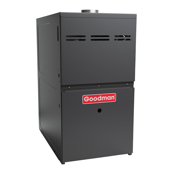
GM9S80, AM9S80, GC9S80, AC9S80, VM9S80, VC9S80 & Accessories
Pride and workmanship go into every product to provide
our customers with quality products. It is possible, however,
that during its lifetime a product may require service.
Products should be serviced only by a qualified service
technician who is familiar with the safety procedures
required in the repair and who is equipped with the proper
tools, parts, testing instruments and the appropriate service
manual. REVIEW ALL SERVICE INFORMATION IN THE
APPROPRIATE SERVICE MANUAL BEFORE
BEGINNING REPAIRS.
Only personnel that have been trained to install, adjust,
service or repair(hereinafter, "service") the equipment
specified in this manual should service the equipment. The
manufacturer will not be responsible for any injury or
property damage arising from improper service or service
procedures. If you service this unit, you assume responsi-
bility for any injury or property damage which may re-
sult. In addition, in jurisdictions that require one or more
licenses to service the equipment specified in this manual,
only licensed personnel should service the equipment.
Improper installation, adjustment, servicing or repair of
the equipment specified in this manual, or attempting to
install, adjust, service or repair the equipment specified in
this manual without proper training may result in product
damage, property damage, personal injury or death.
80% Single Stage Gas Furnaces
WARNING
Copyright © 2021 Goodman Manufacturing Company, L.P.
TABLE OF CONTENTS
IMPORTANT INFORMATION ............................................ 2
PRODUCT IDENTIFICATION ........................................... 4
SYSTEM OPERATION ...................................................... 5
SCHEDULED MAINTENANCE ....................................... 25
SERVICING ..................................................................... 29
CHECKING VOLTAGE .............................................. 30
CHECKING WIRING .................................................. 30
CHECKING THERMOSTAT, WIRING ....................... 30
CIRCUIT ...................................................................... 31
CHECKING DUCT STATIC ........................................ 32
CHECKING TEMPERATURE RISE .......................... 32
CHECKING PRIMARY LIMIT CONTROL ................. 33
CHECKING AUXILIARY LIMIT CONTROL ............... 33
CHECKING FLAME ROLLOUT CONTROL ............. 34
INDUCED DRAFT BLOWER MOTOR ...................... 35
CHECKING GAS VALVE (REDUNDANT) ................ 35
CHECKING MAIN BURNERS ................................... 35
CHECKING ORIFICES .............................................. 35
CHECKING GAS PRESSURE .................................. 36
CHECKING HOT SURFACE IGNITER ..................... 38
CHECKING FOR FLASHBACK ................................. 38
CHECKING PRESSURE SWITCH............................ 38
HIGH ALTITUDE APPLICATION ............................... 39
CHECKING FOR DELAYED IGNITION .................... 39
BOARDS ..................................................................... 40
CHECKING FLAME SENSOR ................................... 40
AIRFLOW TABLES ........................................................ 42
1 STAGE STATUS CODES ........................................... 50
1 STAGE TROUBLESHOOTING CODES.................... 52
WIRING DIAGRAMS ....................................................... 54
RS6621008
July 2021
Advertisement
Table of Contents

Related Manuals for Goodman GM9S80


Summary of Contents for Goodman GM9S80
-
Page 1: Table Of Contents
Service and Troubleshooting 80% Single Stage Gas Furnaces GM9S80, AM9S80, GC9S80, AC9S80, VM9S80, VC9S80 & Accessories TABLE OF CONTENTS Pride and workmanship go into every product to provide our customers with quality products. It is possible, however, that during its lifetime a product may require service. -
Page 2: Important Information
IMPORTANT INFORMATION IMPORTANT NOTICES RECOGNIZE SAFETY SYMBOLS, WORDS AND LABELS Pride and workmanship go into every product to provide our customers with quality products. It is possible, however, that during its lifetime a product may require service. Products should be serviced only by a qualified service technician who is familiar with the safety procedures required in the repair and who is equipped with the proper tools, parts, testing in- struments and the appropriate service manual. - Page 3 IMPORTANT INFORMATION WARNING If the information in these instructions is not followed exactly, a fire or explosion may result causing property damage, personal injury or loss of life. - do not store or use gasoline or other flammable vapors and liquids in the vicinity of this or any other appliance. - WHAT TO DO IF YOU SMELL GAS: •...
-
Page 4: Product Identification
The model and manufacturing number are used for positive identification of component parts used in manufacturing. Please use these numbers when requesting service or parts information. Brand Minor Revision G - Goodman® Brand A - Initial Release V - GMC® Brand B - 1st Revision A- AMANA®... -
Page 5: System Operation
SYSTEM OPERATION NORMAL SEQUENCE OF OPERATION 8. Circulator blower is de-energized following a fixed for- ty five (65) second cool off delay period. 9. Furnace awaits next call from thermostat. Power Up 1. 115 VAC power applied to furnace. Fan Only Mode 2. - Page 6 SYSTEM OPERATION If it is necessary for the installer to supply additional line voltage wiring to the inside of the furnace, the wiring must applicable codes. The furnace must be electrically grounded conform to all local codes, and have a minimum temperature in accordance with local codes or, in their absence, with the rating of 105°C.
- Page 7 SYSTEM OPERATION Twinning If it is necessary for the installer to supply additional line Two furnaces of the same model may be twinned. The in- voltage wiring to the inside of the furnace, the wiring must tegrated control board has a 3/16” terminal labeled “TWIN” conform to all local codes, and have a minimum temperature located beside the low voltage thermostat connection strip.
- Page 8 SYSTEM OPERATION • The control verifies that pressure switch circuit is open (0 VAC on Pin 5). • The control module performs a gas valve circuitry check to verify gas valve relay state and presence of voltage at the valve. •...
- Page 9 SYSTEM OPERATION 3. When the center switch is pressed, the current dis- Cooling Mode Speed Selection played speed will be selected, and control will imme- To change the main blower speed in COOLING mode, fol- diately apply that speed setting. low the following steps: 1.
- Page 10 State of California to cause cancer, birth de- fects or other reproductive harm. Goodman & Amana 80% furnaces are ETL certified appli- ® ances and are appropriate for use with natural or propane gas.
- Page 11 SYSTEM OPERATION Location Requirements and Considerations • Seal off a non-direct vent furnace if it is installed near an area frequently contaminated by any of the above WARNING substances. This protects the non-direct vent furnace from airborne contaminants. To ensure that the enclosed To prevent possible equipment damage, personal injury or non-direct vent furnace has an adequate supply of death, the following bullet points must be observed when...
- Page 12 SYSTEM OPERATION After it has been determined that each appli- PROVIDE 8" MINIMUM CLEARANCE BETWEEN CENTER ROD AND FURNACE CABINET TO ance connected to the venting system properly ALOW FOR CIRCULATOR BLOWER REMOVAL. vents when tested as outlined above, return ASSURE FURNACE IS LEVEL FROM ALTERNATE 3/8"...
- Page 13 SYSTEM OPERATION If this furnace is to be installed in the same space with other 9.3.2.1* Standard Method. The minimum required volume gas appliances, such as a water heater, ensure there is an shall be 50 ft per 1,000/Btu/hour (4.8m /kW).
- Page 14 SYSTEM OPERATION Combining spaces in different stories. The volumes of (2)*Where communicating with the outdoors through horizon- spaces in different stories shall be considered as com- tal ducts, each opening shall have a minimum free area municating spaces where such spaces are connected of 1 in.
- Page 15 SYSTEM OPERATION (3) Outdoor Opening(s) Size. The outdoor opening(s) size 9.3.8.1 Ducts shall be constructed of galvanized steel or a shall be calculated in accordance with the following: material having equivalent corrosion resistance, strength, (a) The ratio of the interior spaces shall be the available and rigidity.
- Page 16 SYSTEM OPERATION NOTE: The vertical height of the Category I venting system Masonry Chimneys must be at least as great as the horizontal length of the WARNING venting system. Possibility of property damage, personal injury or death - Damaging condensation can occur inside masonry chimneys WARNING when a single fan assisted Category 1 appliance (80% AFUE fur- nace) is vented without adequate dilution air.
- Page 17 SYSTEM OPERATION 10' or Less Proper Chimney Line, terminate with listed vent cap Termination? (Check 1) (Fix 1) 2' Min. 2' Min. 3' Min. Wall or Parapet Chimney channel free of solid and Change venting Chimney liquid fuel arrangements appliances? (Fix 2) (Check 2) 10' or Less...
- Page 18 SYSTEM OPERATION Tile liner cracked Flexible liners should be hung straight or nearly straight. If it No tile liner is spiraled in the chimney and in good condition, it should be Salt staining at mortar joints. (White stains, and rehung. To do this, break the top seal; pull up and cut off the mortar becomes sandy and/or erodes.) excess liner length, and refit the top seal.
- Page 19 SYSTEM OPERATION Check 7 - Complete the Installation Fix 3 - Rebuild the Crown If Checks 1 through 6 have been satisfactory, and the liner is If the chimney crown is damaged, a qualified mason must an acceptable size as determined by the tables in National repair it in accordance with nationally recognized building Fuel Gas Code NFPA 54/ANSI Z223.1 - latest edition and codes or standards.
- Page 20 SYSTEM OPERATION For sizing of flexible liners, see Note 22 and the tables in the This furnace is shipped from the factory configured for nat- National Fuel Gas Code NFPA 54/ANSI Z223.1 - latest edition ural gas at standard altitude. Propane gas installations re- and in the National Standard of Canada, CAN/CGA B149.1 quire an orifice change to compensate for the energy con- and CAN/CGA B149.2 - latest editions and amendments.
- Page 21 SYSTEM OPERATION provide the proper design certified input rate within the spec- suring the gas supply pressure and manifold pressure are ified altitude range. provided on the valve. High altitude kits are purchased according to the installation NOTE: The gas supply pressure on White-Rodger “J” model altitude and usage of either natural or propane gas.
- Page 22 SYSTEM OPERATION 3. Use ground joint unions. fore pressure testing the supply piping system with pressures 4. Install a drip leg to trap dirt and moisture before it can in excess of 1/2 psig (3.48 kPa). Isolate this unit from the gas enter the gas valve.
- Page 23 SYSTEM OPERATION Sizing Between Second or Second Stage Regulator & Appliance* Maximum Propane Capacities listed are based on 1/2" W.C. pressure drop at 11" W.C. setting. WARNING Capacities in 1,000 BTU/hour. Pipe or Nominal Pipe Size If the gas furnace is installed in a basement, an excavated area Tubing Size, O.D.
- Page 24 SYSTEM OPERATION original wire as supplied with the furnace must be replaced, A closed return duct system must be used, with the return it must be replaced with wiring material having a tempera- duct connected to the furnace. NOTE: Ductwork must never ture rating of at least 105°...
-
Page 25: Scheduled Maintenance
SCHEDULED MAINTENANCE Remember that dirty filters are the most common cause of WARNING inadequate heating or cooling performance. HIGH VOLTAGE WARNING Disconnect ALL power before servicing or changing any electrical wiring. Multiple pow- er sources may be present. Failure to do so HIGH VOLTAGE may cause property damage, personal injury Disconnect ALL power before servicing, re-... - Page 26 SCHEDULED MAINTENANCE Induced Draft and Circulation Blowers Test Equipment The bearings in the induced draft blower and circulator blow- Proper test equipment for accurate diagnosis is as essential er motors are permanently lubricated by the manufacturer. as regular hand tools. No further lubrication is required.
- Page 27 SCHEDULED MAINTENANCE CLOCKING A GAS METER 1. Turn off all gas appliances in the home. 2. Turn on the furnace. Ensure the furnace is operating at a 100% firing rate on 2 stage and modulating furnace product. 3. Once heating cycle is at a steady state (typically 15 minutes of operation), use a stopwatch to time how long it takes the smallest unit of measure dial on the gas meter to make a full revolution.
- Page 28 SCHEDULED MAINTENANCE 5. Use this formula to verify the Cubic Feet per Hour (CFH) input determined in step 4 is correct: (3600 x Gas Meter Dial Size) / Time (seconds) = Cubic Feet per Hour (CFH) 3600 is used as there are 60 seconds in a minute and 60 minutes in an hour.
-
Page 29: Servicing
SERVICING INCOMING POWER 120.00 0.00 THIS IS L1 OR THE THIS IS THE COMMON HOT POWER LEG OR NEUTRAL LEG These then should be wired to the furnace accordingly. CHECKING FOR PHASING - PRIMARY TO SECONDARY OF UNMARKED TRANSFORMERS* METER READS METER READS 120 VOLTS 24 VOLTS... -
Page 30: Checking Voltage
SERVICING CHECKING VOLTAGE CHECKING THERMOSTAT, WIRING WARNING WARNING HIGH VOLTAGE Disconnect ALL power before servicing. Disconnect ALL power before servicing or 1. Remove the blower compartment door to gain access changing any electrical wiring. Multiple pow- er sources may be present. Failure to do so to the thermostat low voltage wires located at the fur- may cause property damage, personal injury nace integrated control module terminals. -
Page 31: Checking Air Circulator Blower Motor
SERVICING CHECKING AIR CIRCULATOR BLOWER MOTOR Some of the electronic boards being used today, with flame rectification, will not function properly and/or at all without WARNING polarization of incoming power. Some also require phas- ing between the primary and secondary sides of step-down Disconnect ALL power before servicing. -
Page 32: Checking Duct Static
SERVICING Motor Tap Identification CONNECTOR ID DESCRIPTION CONNECTOR VOLTAGE LINE, L1 LINE, L1 GROUND CHASSIS GROUND LINE, L2 LINE, L2 SIGNAL COMMON 24VAC COMMON TAP 1 24VAC TAP 2 24VAC TAP 3 24VAC TAP 4 24VAC TAP 5 24VAC . WARNING Disconnect ALL power before servicing. -
Page 33: Checking Primary Limit Control
SERVICING 3. Subtract the return air temperature from the supply 1. Remove burner compartment door to gain access to air temperature to determine the air temperature the primary limit. rise. Allow adequate time for thermometer readings 2. Remove low voltage wires at limit control terminals. to stabilize. -
Page 34: Checking Flame Rollout Control
SERVICING The control is designed to open should a flame roll out oc- WARNING cur. An over firing condition or flame impingement on the heat shield may also cause the control to open. If the rollout control opens, the air circulation blower will run continuously. HIGH VOLTAGE Disconnect ALL power before servicing or in- stalling this unit. -
Page 35: Induced Draft Blower Motor
SERVICING INDUCED DRAFT BLOWER MOTOR WARNING HIGH VOLTAGE Disconnect ALL power before servicing or in- stalling this unit. Multiple power sources may .023" - .027" be present. Failure to do so may cause proper- ty damage, personal injury or death. 1. -
Page 36: Checking Gas Pressure
SERVICING NOTE: Use adapter kit #0151K00000S to measure gas pressure on White-Rodgers 36J22 gas valves. STREAM B The length of Dimension “A” determines the angle of Gas Stream “B”. DENT OR BURR STREAM B . A dent or burr will cause a severe deflection of the gas stream. - Page 37 SERVICING Gas Manifold Pressure Measurement Measure the gas manifold pressure with burn- and Adjustment ers firing. Adjust manifold pressure using the Manifold Gas Pressure table shown below. CAUTION Remove regulator cover screw from the outlet pressure regulator adjust tower and turn screw To prevent unreliable operation or equipment damage, the gas clockwise to increase pressure or counterclock- manifold pressure must be as specified on the unit rating plate.
-
Page 38: Checking Hot Surface Igniter
SERVICING Gas Valve On/Off WARNING Selector Inlet Pressure Switch Line Voltage now present. 6. After checking and/or replacing of hot surface ignitor, OUTLET INLET reinstall burner compartment door and verify proper unit operation. Pressure Regulator Outlet Pressure Adjustment CHECKING FOR FLASHBACK (Under Cap Screw) Flashback will also cause burning in the burner venturi, but White-Rodgers Model 36J22 (Single-Stage) -
Page 39: High Altitude Application
SERVICING In some areas the gas supplier may artificially derate the gas in an effort to compensate for the effects of altitude. If the gas is artificially derated the appropriate orifice size must be determined based on the BTU/ft content of the derated gas and the altitude. -
Page 40: Checking Flame Sensor
SERVICING Flame Sensor WARNING Line Voltage now present. These tests must be completed within a given time frame due to the operation of the ignition control. NOTE: The models use White-Rodgers 50X57- 290 1. Check for 120 volts from Line 1 (Hot) to Line 2 (Neu- tral) at the ignition control. - Page 41 SERVICING *M9S80 / *C9S80 Pressure Switch Trip Points And Usage Chart ID BLOWER Set Point on Max Make MODEL Pressure Switch Pressure Fall (PF) Pressure On Part# W.C. Rise W.C. *M9S800403A* -0.70 ±0.06 -0.85 0130F00505 *M9S800603A* -0.90 0130F00506 -0.75 ±0.07 *M9S800603B* -0.75 ±0.07 -0.90...
-
Page 42: Airflow Tables
AIRFLOW TABLES GM9S80 LOW STAGE COOLING AIRFLOW EXTERNAL STATIC PRESSURE, (INCHES WATER COLUMN) THERMOSTAT MODEL TAP # CALL F04^ *M9S800403A* Y/Y1 1330 1295 1273 1251 1223 1195 1168 1142 1130 1090 1059 1022 1158 1113 1090 1057 1024 1270 1235... - Page 43 AIRFLOW TABLES GM9S80 HIGH STAGE COOLING AIRFLOW EXTERNAL STATIC PRESSURE, (INCHES WATER COLUMN) THERMOSTAT MODEL TAP # CALL *M9S800403A* F05^ 1330 1295 1273 1251 1223 1195 1168 1142 1130 1090 1059 1022 1158 1113 1090 1057 1024 1270 1235 1208...
- Page 44 AIRFLOW TABLES GM9S80 CIRCULATION AIRFLOW EXTERNAL STATIC PRESSURE, (INCHES WATER COLUMN) THERMOSTAT MODEL TAP # CALL *M9S800403A* 1330 1295 1273 1251 1223 1195 1168 1142 1130 1090 1059 1022 1158 1113 1090 1057 1024 1270 1235 1208 1179 1147 1119...
- Page 45 AIRFLOW TABLES GM9S80 HEATING AIRFLOW EXTERNAL STATIC PRESSURE, (INCHES WATER COLUMN) THERMOSTAT MODEL TAP # TEMP RANGE CALL RISE RISE RISE RISE RISE F01^^ F02^ *M9S800403A* W/W1 25-55 F01^^ F02^ 1268 1221 1188 1154 1122 1091 1060 1029 *M9S800603A* W/W1...
- Page 46 AIRFLOW TABLES GC9S80 LOW STAGE COOLING AIRFLOW EXTERNAL STATIC PRESSURE, (INCHES WATER COLUMN) THERMOSTAT MODEL TAP # CALL 1120 1081 1053 1022 F04^ 1073 1031 1003 *C9S800403A* Y/Y1 1212 1198 1161 1138 1103 1076 1037 1007 1274 1252 1220 1195 1169 1145 1110...
- Page 47 AIRFLOW TABLES GC9S80 HIGH STAGE COOLING AIRFLOW EXTERNAL STATIC PRESSURE, (INCHES WATER COLUMN) THERMOSTAT MODEL TAP # CALL 1120 1081 1053 1022 1073 1031 1003 F05^ *C9S800403A* 1212 1198 1161 1138 1103 1076 1037 1007 1274 1252 1220 1195 1169 1145 1110 1084...
- Page 48 AIRFLOW TABLES GC9S80 CIRCULATION AIRFLOW EXTERNAL STATIC PRESSURE, (INCHES WATER COLUMN) THERMOSTAT MODEL TAP # CALL 1120 1081 1053 1022 1073 1031 1003 *C9S800403A* 1212 1198 1161 1138 1103 1076 1037 1007 1274 1252 1220 1195 1169 1145 1110 1084 1362 1342 1307...
- Page 49 AIRFLOW TABLES GC9S80 HEATING AIRFLOW EXTERNAL STATIC PRESSURE, (INCHES WATER COLUMN) THERMOSTAT MODEL TAP # TEMP RANGE CALL RISE RISE RISE RISE RISE F01^^ F02^ 1120 1081 1053 1022 *C9S800403A* W/W1 25-55 1073 1031 1003 F01^^ F02^ 1035 *C9S800603A* W/W1 30-60 F04^^ F01^^...
-
Page 50: Stage Status Codes
1 STAGE STATUS CODES LED Display Menu Description Notes Main Option Menu Menu ( xx: code numbers ) Active Alarm menu xx ( xx: code numbers ) Last 6 Faults xx Code Release Number CR Number yes, no Reset to Factory Default ... - Page 51 1 STAGE STATUS CODES STATUS MENU Main Mode Menu Idle Continous Fan Compressor Cooling, Low Stage Compressor Cooling, High Stage Gas heat - Single Stage Control OEM test Mode ...
-
Page 52: Stage Troubleshooting Codes
1 STAGE TROUBLESHOOTING CODES TROUBLESHOOTING CHART Symptom Fault Description Corrective Actions Status Normal operation Normal operation None Locate and correct gas interruption Replace or realign igniter Furnace lockout due to an excessive number Check flame sense signal, clean sensor if coated or of ignition “retries”... - Page 53 1 STAGE TROUBLESHOOTING CODES TROUBLESHOOTING CHART Symptom Fault Description Corrective Actions Status Flame sense micro amp signal is minimal Clean flame sensor if coated or oxidized Inspect for proper Flame sensor is coated/oxidized flame sensor alignment Flame sensor incorrectly positioned in burner Normal furnace operation ...
-
Page 54: Wiring Diagrams
WIRING DIAGRAMS POWER BEFORE PROPERLY POLARIZED 40 VA TRANSFORMER TH (3) RLI (12) HLO (1) PS1(5) READ CODES FROM LEFT TO RIGHT HLI (8) MV (10) MVC (11) TR (7) W/W1 R Y/Y1 Y2 ECM MTR INDOOR HARNESS CIRCULATOR MICRO BLWR INTERGRATED CONTROL MODULE NOTES:... - Page 55 GOODMAN BRAND ® AMANA BRAND ® is a registered trademark of Maytag Corporation or its related companies and is used under license. All rights reserved. ® Copyright © 2021 Goodman Manufacturing Company, L.P.