
Related Manuals for Toshiba B-FP2D Series


Summary of Contents for Toshiba B-FP2D Series
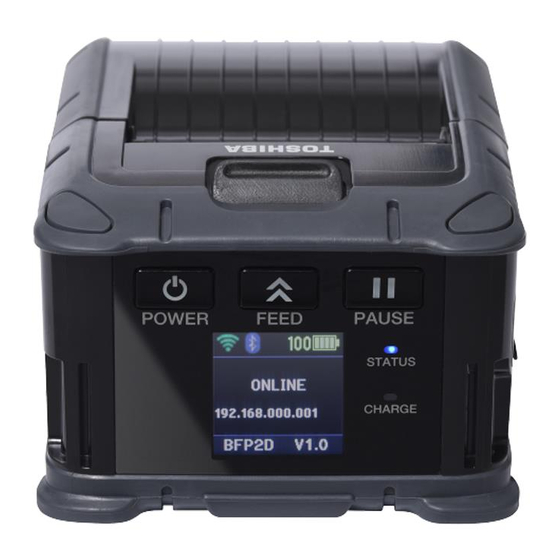
- Page 1 TOSHIBA Potable Printer B-FP2D SERIES Maintenance Manual Document No. SPTM-0325A Original: Dec., 2019 (Revised: Feb., 2020) Preliminary version (IP54 not supported)
- Page 2 WARNING! Follow all manual instructions. Failure to do so could create safety hazards such as fire or electrocution. NOTE: Failure to follow manual instructions or any unauthorized modification, substitution or change to this product will void the limited product warranty.
-
Page 3: Table Of Contents
2.14 Replacing the Battery Terminal ..................2- 18 3. TROUBLESHOOTING ....................3- 1 CAUTION! 1. This manual may not be copied in whole or in part without prior written permission of Toshiba tec. 2. The contents of this manual may be changed without notification. -
Page 4: Unpacking
UNPACKING 1.1 Procedure Open the carton. Unpack the accessories from the carton. Unpack the printer. B-FP3D B-FP2D NOTE: Keep the carton and pad for future transportation of the printer. 1.2 Checks Check for damage or scratches on the machine. Confirm that none of the accessories are missing. -
Page 5: Major Unit Replacement
2. MAJOR UNIT REPLACEMENT SPTM-0325 2.1 Removing the Function Unit MAJOR UNIT REPLACEMENT WARNING! 1. Disconnect the power cord before installing the main parts. 2. Be careful not to injure your fingers when replacing the main parts. CAUTION! 1. Since a lot of small moulded parts are used in this printer, care must be taken not to damage or lose them. - Page 6 2. MAJOR UNIT REPLACEMENT SPTM-0325 2.1 Removing the Function Unit Push the open button to open the printer. Remove the screws inside the printer. Open Cover Open Button Inside screw Inside screw Remove the fanfold cover and remove the two screws after. Screws Fanfold cover Lift the Top cover as shown below.
-
Page 7: Replacing The Paper Guide Assembly
2. MAJOR UNIT REPLACEMENT SPTM-0325 2.2 Replacing the Paper Guide Assembly Function Unit Replacing the Paper Guide Assembly Open the Printer Cover. Remove the screw inside the printer and lift the Paper Guide Assembly. Screw Paper Guide Assembly Replace the Paper guide Assembly with a new one, then perform reassembly in the reverse order of removal. -
Page 8: Replacing The Platen Assembly
2. MAJOR UNIT REPLACEMENT SPTM-0325 2.5 Replacing the Logic Card 2.3 Replacing the Platen Assembly Continue after Section 2.1 Removing the Function Unit. Loosen or remove the two screws as shown blow. Slowly put down the Lower sensor assembly and lift the Platen Assembly. Careful not to damage the flex. Platen Assembly Lower Sensor Assembly Platen Assembly... -
Page 9: Replacing The Lower Sensor Assembly
2. MAJOR UNIT REPLACEMENT SPTM-0325 2.5 Replacing the Logic Card Replacing the Lower Sensor Assembly Refer to item no. 1 in Section 2.2 Replacing the Platen Assembly. Detached the Lower Sensor PCB from the hooks. Lower Sensor Assembly 3) Push the metal shaft using a pointed tool like a screw driver to remove it together with the two screws. Note: If you want the Lower Sensor PCB only, you can detach the connector directly. - Page 10 2. MAJOR UNIT REPLACEMENT SPTM-0325 2.5 Replacing the Logic Card 5) Remove the black tape on the other side and the bottom side. Black tapes Black tape 6) Slightly pull the Lower Sensor Assembly to detach and access the connector to detach. Lower Sensor Assembly 7) Replace the Lower Sensor Assembly with a new one, then perform reassembly in the reverse order of removal NOTES:...
-
Page 11: Replacing The Logic Card
2. MAJOR UNIT REPLACEMENT SPTM-0325 2.5 Replacing the Logic Card Replacing the Logic Card Refer to item no. 6 in Section 2.4 Replacing the Lower Sensor Assembly Totally pull the Assembly and detach the connectors. Remove the screw also. Screw Detach the Logic card from the plastic hook. -
Page 12: Replacing The Lcd Panel And The Panel Key
2. MAJOR UNIT REPLACEMENT SPTM-0325 2.6 Replacing the LCD Panel and the Panel Key Replacing the LCD Panel and the Panel Key Refer to item no. 3 in Section 2.5 Replacing the Logic Card Detach the LCD Panel from the frame. In addition, peel off the Panel Key to remove also. Panel Key LCD panel NOTE: Proper care should be observed when replacing the LCD Panel and Panel key. -
Page 13: Replacing The Peel Off Unit And Peel Off Sensor
2. MAJOR UNIT REPLACEMENT SPTM-0325 2.8 Replacing the WLAN Board Assembly Replacing the Peel Off Unit and Peel Off Sensor Refer to item no. 7 in Section 2.1 Removing the Function Unit. Press the plastic lever to the side and lift the Peel Off Unit Assembly up. Detach the connector. Push to unlock Pull the FFC Cable Push up the Peel Off Sensor to detach it from the Peel Off Unit. -
Page 14: Replacing The Wlan Board Assembly
2. MAJOR UNIT REPLACEMENT SPTM-0325 2.8 Replacing the WLAN Board Assembly Replacing the WLAN Board Assembly Refer to item no. 7 in Section 2.1 Removing the Function Unit. Remove the four screws holding the Module Cover. Module Cover WLAN Board Detach the connector. -
Page 15: Replacing The Cover Switch Assembly
2. MAJOR UNIT REPLACEMENT SPTM-0325 2.9 Replacing the Cover Switch Assembly Replacing the Cover Switch Assembly Refer to item no. 2 in Section 2.8 Removing the WLAN Board Assembly Detach the switch with the harness from where it is located. Take note of the Harness Routing. Switch On the other side, remove the two screws in order to remove the cover holding the other switch. -
Page 16: Replacing The Upper Sensor Assembly
2. MAJOR UNIT REPLACEMENT SPTM-0325 2.10 Replacing the Upper Sensor Assembly 2.10 Replacing the Upper Sensor Assembly Refer to item no. 3 in Section 2.9 Removing the Cover Switch Assembly Remove the plastic cover. Pull the Upper Sensor from the hooks. Connector Note: If you want the Upper Sensor PCB only, you can detach the connector directly. - Page 17 2. MAJOR UNIT REPLACEMENT SPTM-0325 2.10 Replacing the Upper Sensor Assembly Remove the cable from the connector. NOTE: 1. For this type of connector, you must first open the lock in order for the flex to be removed. Open Close (locked) Pull Replace the Upper Sensor Assembly with a new one, then perform reassembly in the reverse order of removal...
-
Page 18: Replacing The Thermal Head Assembly
2. MAJOR UNIT REPLACEMENT SPTM-0325 2.11 Replacing the Thermal Head Assembly 2.11 Replacing the Thermal Head Assembly After removing the Upper Sensor Assembly, remove the gear as shown in the photo. Push the platen on either side to remove it. Totally pull the platen to remove it. - Page 19 2. MAJOR UNIT REPLACEMENT SPTM-0325 2.11 Replacing the Thermal Head Assembly Push the Open Button and lift to remove it. Pull up the two springs. Open Button Thermal Head Gently pull the connector of the thermal head to remove the assembly. Thermal Head 2-15...
-
Page 20: Replacing The Driver Card
2. MAJOR UNIT REPLACEMENT SPTM-0325 2.12 Replacing the Driver Card 2.12 Replacing the Driver card Continue from Section 2.11 Removing the Thermal Head Assembly. Remove the White FFC Cable from the Driver Card. To do this, get a tweezer or a similar tool to unlock the connector from both sides. -
Page 21: Replacing The Stepping Motor Assembly
2. MAJOR UNIT REPLACEMENT SPTM-0325 2.14 Replacing the Battery Terminal 2.13 Replacing the Stepping Motor Assembly Continue from Section 2.12 Removing the Driver card Pull the black plastic gear on the side and remove the two screws. Gear Push Motor Replace the Stepping Motor Assembly with a new one, then perform reassembly in the reverse order of removal. -
Page 22: Replacing The Battery Terminal
2. MAJOR UNIT REPLACEMENT SPTM-0282 2.13 Replacing the Wireless Charger 2.14 Replacing the Battery Terminal Continue from Section 2.13 Removing the Motor Assembly Turn the Unit upside down. Bend the two ground terminals so that it will fit the hole. Push inside the hole Ground Terminals Carefully pull each terminal in order to detach. -
Page 23: Troubleshooting
3. TROUBLESHOOTING SPTM-0325 3. TROUBLESHOOTING TROUBLESHOOTING Problems Cause Solution The printer is not turned 1. The battery is not loaded correctly. 1. Re-load the battery correctly. 2. The battery terminal is 2. Replace the battery terminal. disconnected from the soldering part. - Page 24 3. TROUBLESHOOTING SPTM-0325 3. TROUBLESHOOTING Problems Cause Solution The printer does not print 1. The sensors are not adjusted 1. Re-adjust the sensors. labels one by one in the properly. strip mode or specified 2. The sensors are not installed 2.
- Page 25 Revision Record Version: 0001 Page Contents 2.6 Replaceing the LCD Panel and the Panel Key. Added note on pinching flat cable when assembling Panel key. Version: 000x Page Contents © 2019-2020 Toshibatec Corporation All right reserved B-FP2D Series Maintenance Manual...