Table of Contents
Advertisement
Quick Links
Advertisement
Table of Contents

Related Manuals for EverFocus 410M


Summary of Contents for EverFocus 410M
- Page 1 INSTRUCTION MANUAL Digital Eight Channels/Four Channels Video Recorder About this manual Before installing and using this unit, please read this Manual carefully. Be sure to keep it handy for later reference. Updated on: Nov. 17th 2005 EDR810H/810M/ 410H/410M V 1.21...
- Page 2 Federal Communication Commission Interference Statement This equipment has been tested and found to comply with the limits for a Class B digital device, pursuant to Part 15 of the FCC Rules. These limits are designed to provide reasonable protection against harmful interference in a residential installation. This equipment generates, uses and can radiate radio frequency energy and, if not installed and used in accordance with the instructions, may cause harmful interference to radio communications.
- Page 3 This advice complies with Part 15 of the FCC Rules. Operation is subject to the following two conditions: (1) this device may not cause harmful interference, and (2) this device must accept any interference received, including interference that may cause undesired operation.
-
Page 4: Safety Warning
WARNING TO REDUCE RISK OF FIRE OR ELECTRIC SHOCK, DO NOT EXPOSE THIS APPLIANCE TO RAIN OR MOISTURE CAUTION DO NOT REMOVE COVER. NO USER SERVICEABLE PARTS INSIDE. REFER SERVICING TO QUALIFIED SERVICE PERSONNEL. Note: This equipment has been tested and found to comply with the limits for a Class A digital device, The changes or modifications not expressly approved by the party responsible for compliance could void the user's authority to operate the equipment. -
Page 5: Safety Precautions
Do not use the appliance in an extreme environment where high temperature or high humidity exists. Use the appliance at temperature within indoor type DVR for 0 humidity below 90%. The input power source for this appliance is AC100~240V. - Page 6 Safety Precautions The lightning flash with an arrowhead symbol, within an equilateral triangle, is intended to alert the user to the presence of uninsulated ” dangerous voltage ” within the product’ s enclosure that may be of sufficient magnitude to constitute a risk of electric shock to persons.
-
Page 7: Important Safeguards
Important Safeguards Important Safeguards Read Instruction---All the safety and operating instructions should be read before the unit is operated. Retain Instructions---The safety and operating instructions should be retained for future reference. Heed Warnings— All warnings on the unit and in the operating instructions should be adhered to. Follow Instructions—... -
Page 8: Table Of Contents
1. PRODUCT INTRODUCTION … … … … … … … … … … … … … … … … … … … … … … … .… … … … 1.1 FEATURES … … … … … … … … … … … … … … … … … … … … … … … … … ..… … … … ..… … … … . 1.2 SPECIFICATIONS…... - Page 9 5. PLAYING BACK… … … … … … … … … … … ..… … … … … … … … … … … … … … … … … ..… … … ... 5.1 NORMAL PLAYBACK… … … … … … .… … … … … … … … … … … … … … … … … … … … … … … … 5.2 SEARCH PLAYBACK …...
-
Page 10: Product Introduction
1. PRODUCT INTRODUCTION The Digital Video Recorder is the industry’ s first full-featured digital video recorder designed specifically for use in security industry. The Digital Video Recorder incorporates all the benefits of digital video recording, is simple to install, and operates just like a VCR. -
Page 11: Specifications
1.2 SPECIFICATIONS Video Format Video Input Video Output Video Compression Recording Resolution Video Display Display Resolution Video Pause 4/8 Alarm Inputs 1 Alarm Output Hard Disk Storage Recording Rate Recording Mode Playback Rate Playback Search Motion Detection Video Loss Detection Event Log User Interface Setup... - Page 12 Title 12-characters title for each camera Ethernet RJ45 connectors for network communication USB for archiving Archive Archive through Wireless transmission (Reserved) RS-232 9-pin female connector for local communication RS-485 for Keyboard connection Audio 2 mono inputs, 2 mono (SPEAKER) outputs Power Rate DC 12V/DC 24V Half size: 320 mm (L) x 215mm (W) x 100mm (H)
-
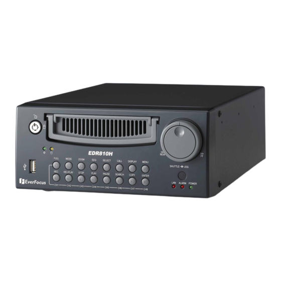
Page 13: Front Panel Keypads
1.3 FRONT PANEL KEYPADS Channel Key: Press FULL+Channel Key (CH1~CH8 ) to display video image in the full screen format the picture of the corresponding will fill the whole screen of the monitor display. CH1 / REC: Press this key to start instant recording. CH2 / REV. - Page 14 MODE: Switch PIP, 4, 7, and 8 displays in Live and Playback modes. ZOOM: Press this key while viewing the full screen image to display a magnified resolution on the monitor. You must be in “Full” screen mode first before zooming. While zooming, all other function keys will be disable until you press “ZOOM”...
- Page 15 Shuttle and Jog Dial Shuttle: In the Playback mode, turn the Shuttle dial to fast forward/rewind Jog Dial: In the Pause mode, turn the Jog dial to forward/rewind the video. USB Slot: Insert a USB to archive an image or video file. HDD LEDs: LEDs for HDD active power (GREEN) and data reading /writing (YELLOW).
-
Page 16: Back Panel Connectors
1.4 BACK PANEL CONNECTORS Back panel of 810M Back panel of 810H Back panel of 410M Back panel of 410H POWER Main Power plug: Connect the DC 12~ 24V power source to adapter for AC 100~ 240V. - Page 17 AUDIO Audio IN: Audio input for recording, and it can be set to “YES” or “NO” in the RECORD SETUP MENU. Audio OUT: Connect to an audio input of a monitor or other device. MONITOR MAIN MONITOR: This connector is used for the main monitor display, a number of different display modes may be selected for viewing.
- Page 18 LAN Connector: The RJ-45 LAN connector. RS232 RS232 connector: Connect D-Sub 9 pins connector to RS232 ports for remote control. RS485 RS485 connector: RJ 45 Connector to Cascade multi Digital Video Recorder. Remote Remote Control: Remote control port provides you an extension wire with an IR receiver instead of the IR receiver on the front panel.
-
Page 19: Monitor Display
1.5 MONITOR DISPLAY The status information of the cameras or machine will show up, and be located at different places on the screen. Channel tag: A channel tag indicates the channel name of the screen. Event sign: Event signals which are small icons with a capital letter and red background show the events on each screen. - Page 20 Select sign: You can assign a camera to a display by pressing SELECT key in life mode. Dial Jog to move the select sign to the display you would like to change camera, and then press FULL + channel key to relocate the camera. Play status bar: The play status bar appears in play back mode if you enable a status bar on the screen (Check page 12, item 15th, DISPLAY).
- Page 21 1. Current date: The current date which is set in the TIME/DATE SETUP MENU. 2. Record status: It shows REC and recording hard disk number. “REC”, it shows when machine is recording. “R01”, the recording hard disk number. There is only one hard disk available in this model, so it always shows R01 when recording.
-
Page 22: Installation
Please refer to the following diagram for the system connections. Note: Monitor and Camera must be purchased separately. RS 232 Camera (VIDEO & AUDIO) Note: 810H/810M without relay 410H/410M with relay Monitor (and Speaker) Call Monitor Antenna (Mobile Model only) -
Page 23: Basic Connections
RJ45 connector Ethernet cable or wireless network (IEEE 802.11b/g). RS232/RS485 Digital Video Recorder is enabled control from the PC or EverFocus keyboard via RS232/RS485. Main/Call Monitor Connect the Main/Call monitor output connector to a Main/Call monitor. The Main/Call monitor displays selected live or recorded cameras in any available format. -
Page 24: Quick Installation Guide For Edr810M & Edr410M Only
Please refer to the following Quick Installation Guide for installing EDR810M or EDR410M into mobile applications such as buses, cars and police cruisers. The DVR can be mounted horizontally (suspend or support mounted). Support EDR410M Interface Show all the possible ways to mount the DVR. - Page 25 Front of bulkhead-horizontal mount Beside deriver seat-horizontal mount Caution: Do not install the DVR on the floor or on the transmission access hatch. These locations have the highest levels of vibration and may be subject to water damage. Convenient operation...
- Page 26 Truck Possible Installation Locations Inside the Automobile Vehicle: Glove box (inside or underneath) Drive seat ( between seat and wall) or Passenger seat (underneath) ( Users are suggested to use “support” for mounting option) Show the wiring on the wiring harness that connects to the electrical system. (24 V) (5 V)
- Page 27 Possible Installation Locations Inside the Automobile Vehicle: TOYOTA CAMRY Glove box (inside or underneath) Trunk (Users are suggested to use “ suspend”for mounting option) Passenger seat (underneath) Drive seat ( between seat and wall) Show the wiring on the wiring harness that connects to the electrical system.
- Page 28 Installing the Camera(s) and Monitor The DVR is typically connected to one camera installed inside the car. Other camera(s) can also be installed in different locations (for example, use the waterproof camera to the outside of vehicle). For installation procedure, refer to the guide that came with the camera(s) you purchased.
- Page 29 Installing the Hard Drive The following figures are for the 3.5”and 2.5”HDD. Figure shows 3.5“ HDD Figure shows 2.5“ HDD...
-
Page 30: Menu Setup
3. MENU SETUP To set up the machine before using is necessary, especially first time to use. Press the MENU key to enter the MAIN MENU. Press the MENU key to quit current setting, and go back to last setting. MENU Dial the Jog clockwise or counterclockwise to change subentry values. - Page 31 In the TIME/DATE SETUP MENU, we define : (1) TIME FORMAT: There are two time formats that are 12 HOUR and 24 HOUR to be selected. (2) TIME: Current time Hour: 00 ~ 23 (1 ~ 12 if TIME FORMAT is 12 HOUR) Minute : 00 ~ 59 Second: 00 ~ 59 (3) DATE FORMAT:...
- Page 32 (6) START TIME: To set the start time of daylight saving time. To set the start month of daylight saving time: Dial the jog to set the start month. To set the start week of daylight saving time: Dial the jog to set the start week. 1 ST 2 ND 3 RD...
- Page 33 (8) TIME SYNCHRONIZE: Select “ON” or “OFF” to enable or disable time synchronize which can let you have correct time automatically when network is connected. (9) TIME SERVER: You can set the time server address where you locate if you connect to network and enable time synchronize.
-
Page 34: Camera Setup Menu
3.2 CAMERA SETUP MENU In the CAMERA SETUP MENU, we define : (1) TITLE: The title setting allows you to assign a title to each camera input. Titling with 12 characters is supported in each channel. The available alphanumeric characters are: 0,1,2,3,4,5,6,7,8,9, A,B,C,D,E,F,G,H,I,J,K,L,M,N,O,P,Q,R,S,T,U,V,W,X,Y,Z, ( ) . - Page 35 (5) REC QUALITY: Select an image quality for recording. Normal record image quality and event record image quality can be set individually. There are six different qualities available. A higher image quality needs more HDD space. The theory space needed per second lists below: ESTIMATE BIT SIZE SUPERIOR : 4.0 Mega Bits/sec...
- Page 36 (7) SUMMARY : Dial Jog to change items in the SUMMERY table. All camera ’s statuses are shown in the SUMMARY table. The table is for checking camera overall statuses only, not for setting. Note: The SUMMARY table also exists in ALARM, MOTION and VLOSS SETUP MENU. All of these SUMMARY tables are also for checking particular overall statuses, not for setting.
-
Page 37: Record Setup Menu
3.3 RECORD SETUP MENU In the RECORD SETUP MENU, we define : (1) RECORD AUDIO: YES: Audio will be recorded when machine is recording. NO: Audio will not be recorded when machine is recording. (2) TIME STAMP: ON: The time stamp will show on the video and picture when recording. OFF: The time stamp will not show on the video and picture when recording. - Page 38 (6) RECORD MODE: REWRITE: Continue recording. Disk will be overwritten if it is full. STOP: Stop recording when disk is full.
-
Page 39: Alarm Setup Menu
3.4 ALARM SETUP MENU In the ALARM SETUP MENU, we define : (1) ALARM: ENABLE: Enable alarm detection. DISABLE: Disable alarm detection. (2) ALARM TYPE: N. O. : Normal Open alarm. N. C. : Normal Close alarm. N.O. Trans.: When the alarm is triggered, buzzer starts to function no matter how long the alarm duration is set until you set it back to N.O. - Page 40 (4) DURATION: Buzzer noise and event record duration of an alarm, from 1 sec to 99 seconds. The default value is 5 seconds. (5) ALARM OUTPUT: The setting of alarms which are NONE and 1, where 1 means the alarm is enabled. (6) ALARM EMAIL: Select “YES”...
-
Page 41: Motion Setup Menu
3.5 MOTION SETUP MENU In the MOTION SETUP MENU, we define : (1) MOTION: ENABLE: Enable motion detection. DISABLE: Disable motion detection. Note: Motion only works in live and playback modes. It is invalid when you are setting menus. (2) SENSITIVITY: The sensitivity allows users to adjust to a suitable motion detection sensitivity. - Page 42 (5 ) EMAIL/NETWORK: YES: Send an email / Enable alarm network when an alarm occurs. NO: Do not send an email / Disable alarm network when an alarm occurs. The email address and e-mail server can be set in the NETWORK SETUP MENU. (6) BUZZER: Motion buzzer.
- Page 43 (10) EDIT MULTIPLE MOTION AREA Enter a desired channel, and press SELECT to edit a motion area. Please make sure that MOTION is set as “Enable” before entering the motion detection area. To test a motion area: Grids will turn into light red from light green when a motion is detected. To clean up the entire area: Press PLAY to clean up the entire motion area.
-
Page 44: Vloss Setup Menu
3.6 VLOSS SETUP MENU In the VLOSS (Video Loss) SETUP MENU, we define : (1) VLOSS: ENABLE: Enable video loss detection. DISABLE: Disable video loss detection. (2) DURATION: Buzzer noise and event record duration of an alarm, from 1 sec to 99 seconds. The default value is 5 seconds. - Page 45 (6) ALARM NETWORK: YES: Enable alarm network. NO: Disable alarm network. (7) SUMMARY: All video loss’s statuses are shown in SUMMARY tables. These tables are for checking video loss overall statuses, but not for setting.
-
Page 46: Network Setup Menu
3.7 NETWORK SETUP MENU There are 5 subentries that are CONFIG, ALARM, EMAIL PASSWORD, and WIRELESS in the NETWORK SETUP MENU. Each of them has to be set up completely before the network functions. 3.7.1 CONFIG Please Note: Since every Network Configuration is different, please contact your Network Administrator or ISP for how to assign those IP addresses and port numbers. - Page 47 Please Note: Since every Network Configuration is different, please contact your Network Administrator or ISP for how to assign those IP addresses and port numbers. DVR can send out Alarm message to an Alarm Server. In the ALARM of the NETWORK SETUP MENU, we define: (1) PROTOCOL: Select which communication protocol with Alarm servers or Alarm receiving clients.
- Page 48 (4) SERVER 1 : assign the IP address of Alarm server 1. (5) SERVER 2 : assign the IP address of Alarm server 2. (6) SERVER 3 : assign the IP address of Alarm server 3. 3.7.3 EMAIL In the EMAIL of the NETWORK SETUP MENU, we define : (1) SMTP SERVER: assign the SMTP (e-mail) server’s IP address.
- Page 49 For example: In Motion Setup Menu, if the “EMAIL/NETWORK” is set to “YES”, this e-mail address will receive a text message and an “ARV” format of a still image from DVR when Motion is triggered. This “ARV” file can be played back by opening “EDRViewer.exe” that you downloaded from the DVR or the Remote Viewer.
- Page 50 3.7.5 WIRELESS (This section is reserved for models that have WIRELESS function) In the WIRELESS of the NETWORK SETUP MENU, we define : (1) DHCP: Enable or disable the Dynamic Host Communication Protocol. YES: Enable DHCP service. NO: Disable DHCP service. (2) IP ADDRESS: Assign an IP address for this unit, for example:192.168.010.200 When DHCP is YES, the DHCP server will assign this value automatically.
-
Page 51: Schedule Setup Menu
3.8 SCHEDULE SETUP MENU In the SCHEDULE SETUP MENU, we define : (1) DAY: MON (Monday), TUE (Tuesday), WED (Wednesday), THU (Thursday), FRI (Friday), SAT (Saturday), SUN (Sunday). WDAY: Weekday, from Monday to Friday. WEND: Weekend, Saturday and Sunday. DLY: Daily. (2) START: The start time of a scheduled record time zone. -
Page 52: Disk Setup Menu
3.9 DISK SETUP MENU In the DISK SETUP MENU, we define : (1) DISK INFORMATION: Only one disk is available in this model. (2) DISK VIDEO DELETE: Select the disk that you wish to delete, then press SELECT button from the front panel to start deletion. -
Page 53: Control Setup Menu
DATA BIT: Select data bit : 7 or 8. The default setting from the factory is 8. Note: RS 485 pin definition is shown in APPENDIX B. (3) RS 232 / RS 485 ID: Select ID from 001 to 255. (4) PTZ PROTOCOL: Select PTZ protocol from EVERFOCUS , PELCO-D, PELCO-P and ED2200/2250. -
Page 54: Warning Setup Menu
3.11 WARNING SETUP MENU In Warning Setup Menu, you will be able to do warning setting when the following situations occur: 3.11.1 FAN FAULT In FAN FAULT, we define: BUZZER: Fan buzzer. ENABLE: To enable a buzzer when the fan does not work. DISABLE: To disable buzzer. -
Page 55: Hdd Temp
3.11.2 HDD TEMP. In HDD TEMP., we define: BUZZER: HDD TEMPERATURE buzzer. ENABLE: To enable a buzzer when HDD’s temperature is over 70 ° C. DISABLE: To disable buzzer. ALARM OUTPUT: The setting of alarms which are NONE and 1, where 1 means the alarm is enabled. ALARM DURATION: PERMANENT NETWORK ALARM: YES: To enable network alarm. - Page 56 3.11.3 NO HDD In NO HDD, we define: BUZZER: NO HDD buzzer. ENABLE: To enable a buzzer when no HDD has been found. DISABLE: To disable buzzer. ALARM OUTPUT: The setting of alarms which are NONE and 1, where 1 means the alarm is enabled. ALARM DURATION: Buzzer noise and event record duration of an alarm, from 1 sec to 99 seconds.
-
Page 57: Hdd Full
3.11.4 HDD FULL In HDD FULL, we define: BUZZER: HDD FULL buzzer. ENABLE: To enable a buzzer when HDD is full. DISABLE: To disable buzzer. ALARM OUTPUT: The setting of alarms which are NONE and 1, where 1 means the alarm is enabled. ALARM DURATION: Buzzer noise and event record duration of an alarm, from 1 sec to 99 seconds. -
Page 58: System Setup Menu
3.12 SYSTEM SETUP MENU In the SYSTEM SETUP MENU, we define : (1) SYSTEM VERSION: Current system firmware version. (2) SYSTEM VIDEO FORMAT: NTSC or PAL. System can detect the input signal type automatically from camera 1 while system is booting up. Users do not need to set it up. Note: The signal type is detected by the camera 1, so camera 1 input has to be connected. - Page 59 (5) CALL MON QUAD SEQ: The retention period of the call monitor quad display in the sequence mode. Note: Please refer to CALL setting for an advanced call monitor setting. (6) LANGUAGE: Note: Three languages are available to be chosen: English, Chinese and Japanese. Subject to change without further notice.
- Page 60 Note: After upgrading system software, please do the following actions before recording: Load System Default in System Setup Menu. Delete disk in Disk Setup Menu. LEVEL LEVEL-3 RIGHT ADMINISTRATOR DISPLAY MODE ZOOM FULL SELECT CALL MENU COPY SEARCH PLAY STOP REV.PLAY PAUSE Note: The above table will be updated if there is any change.
-
Page 61: Recording
4. RECORDING 4.1 INSTANT RECORDING Press the Record key to start recording immediately. When REC is pressed, the pictures being monitored will be recorded in the HDD. • The recording rate, recording quality and recording speed can be set in the CAMERA SETUP MENU. -
Page 62: Schedule Recording
4.2 SCHEDULE RECORDING Set up the DAY, START time, END time and then enable SET function in the SCHEDULE SETUP MENU. Please refer to SCHEDULE SETUP MENU, to see setting procedure and more details. 4.3 EVENT RECORDING We define two event types which are ALARM and MOTION events that can be recorded. After the event recording is enabled, the EDR810/410 will start an event recording when an event occurs. -
Page 63: Alarm Input Recording
2. After enable an event, you need to set a time zone in the SCHEDULE SETUP MENU. An event recording has to be included in a scheduled time zone. You can refer to SCHEDULE SETUP MENU to set up a time zone which you would like to record when an event occurs. 3. -
Page 64: Playing Back
5. PLAYING BACK 5.1 NORMAL PLAYBACK (1) Playback Press the PLAY key to start playing back the stored image/audio. The video start time depends on the immediate play setting in the SYSTEM SETUP MENU. PLAY Press the REV. PLAY key to start reverse playing back the stored image/audio from the last segment. - Page 65 (4) Slow Forward/Reverse Playback During playback mode, press PAUSE key to freeze the playing back picture. PAUSE Turn the Shuttle dial clockwise, to start slow forward playback. The speed will show on the status bar of the bottom screen. >> 1/2, 1/4, 1/8, 1/16, 1/32, and press ENTER at the same time to fasten the play speed.
-
Page 66: Search Playback
5.2 SEARCH PLAYBACK Press the SEARCH key to enter the SEARCH MENU. SEARCH In the SEARCH MENU, Dial the Jog clockwise or counterclockwise to change subentry values. Press ENTER key to go next subentry in search menu setting, and press DISPLAY key to go last subentry in search menu setting. - Page 67 (2) EVENT Search Playback You can change different event search methods if you select “BY EVENT” instead of “BY TIME / DATE” . 7 events which are ALARM, MOTION, VLOSS, A/M, A/V, M/V and A/M/V can be selected. The indications of events show as below. EVENT ALARM Search ALARM events...
-
Page 68: Copy To A Video File
6. COPY TO A VIDEO FILE Insert a USB pocket driver into USB slot on the front panel to copy. USB SLOT: Digital Video Recorder allows users to select the camera for copying image to movie file or copying EDR Viewer player. - Page 69 In the COPY MENU, we define: COPY: Select Image for copying images to movie file. Select Viewer for copying EDR viewer player. DISK NO: Disk number. It is fixed as “01” in this series. CAMERA NO: Camera channel number. You can select the video of camera you would like to copy. START DATE &...
-
Page 70: Call
7. CALL Press the CALL key and the CALL MENU will pop up as below. In CALL MENU, we define : (1) SEQ: Sequence display on the call monitor. Press SEQ to switch “ON” or “OFF” of the sequence status. (2) OSD: Channel name display on the call monitor. - Page 71 (b) SEQ is ON: When QUAD DISPLAY is “NO”, the call monitor displays a sequence full screen of each channel. When QUAD DISPLAY is “YES” (enabled), the call monitor displays a sequence quad screen.
-
Page 72: Screen Display Setting
8. SCREEN DISPLAY SETTING In a full screen display, press SELECT key to pop up the display adjustment window as below: In the screen display setting menu, we define: (1) CAMERA: The display setting of the current camera. (2) BRIGHTNESS: The bright percentage of the current camera; from 0% to 100%. (3) CONTRAST: The contrast percentage of the current camera;... -
Page 73: Screen Display Mode
9. SCREEN DISPLAY MODE Press MODE to switch 4, 7, 8, and PIP (picture in picture) displays for Live and Playback mode. -
Page 74: Remote Viewer
10. REMOTE VIEWER Basic Operations and Login Display: Go to the Internet Explorer, key in the network IP address, for example, http://220.228.98.9 (must be the same IP address as the one assigned to the unit from the Network Setting Menu. please contact your ISP or MIS for the IP assignment) The LOGIN dialog will be shown on the screen. -
Page 75: Main Screen
Main Screen The above diagram is the main screen display. The icons on the lower corner of the screen are mainly for control and configuration, those on the right corner are for status indication. If any icon is grayed, it means that the specific function is not accessible in the current mode. The followings are a brief description for each of the icons. - Page 76 7. The system allows up to 3 ways to playback video, by EVENT LIST, Time and PTZ Control. (Playback by EVENT LIST, click “Update” button to show list) (Playback by Time) (Playback by PTZ Control)
- Page 77 Search from EVENT LIST: Select Event Type from Alarm, Motion and Vloss. Press Update button to refresh the event list. III. All events of the selected type will be displaying along with Date/Time, event type (represents by a capital letter), camera number (represents by a number), e.g.
- Page 78 14. Quad screen view. 15. Nine split screen view. 16. A pop-up menu to select camera to view will be shown by right-clicking the mouse. 17. Download viewer I. To download viewer, press “EverFocus” logo on the right top corner of the screen.
- Page 79 II. Select “Run” or “Save” the file. III. Open the EDRViewer.exe for loading the archived EDR MPEG Files (.arv) Note: If you are unable to play “AVI” file downloaded from “EDRViewer”, please go to the following URL: http://www.divx.com/divx/play/download/index .php for downloading DivXPlay.exe. This will enable you to play “AVI” file successfully.
-
Page 80: Appendix A: Rs232 Specifications
APPENDIX A : RS232 specifications This Digital Video Recorder can be controlled by a computer or a terminal via a RS232 standard D-SUB 9-pin RS-232 connector. D-SUB 9-pin connector The pin assignment of the 9-pin D-SUB connector Digital Video Recorder PIN # NAME NOT CONNECTED... -
Page 81: Appendix B: Rs485 Specifications
APPENDIX B : RS-485 (RJ45) specifications There are two RS-485 (RJ-45) connectors of one port on the back panel of the DVR. Please refer to the following pin assignment for application. APPENDIX 1 2 3 4 5 6 7 8... -
Page 82: Appendix C: Alarm I/O Assignment
Each alarm input requires two wires, one wire connects to the desired alarm input pin, the second wire connects to the ground.The alarm signal assignment is shown as below. <Figure 1> D-SUB 25 pin female connector (DVR) PIN # NAME... -
Page 83: Appendix D: Troubleshooting
APPENDIX D : Troubleshooting If the above error message pops up when you connect to EDR1680 for viewing from internet, you should change Internet Option of IE to enable ActiveX controls. Select Tools -> Internet Options … Please refer to the above steps for changing Security Options to Low. APPENDIX... - Page 84 Albert-Einstein-Strasse 1 D-46446 Emmerich, Germany TEL: 49-2822-9394-0 www.everfocus.de Your EverFocus product is designed and manufactured with high quality materials and components which can be recycled and reused. This symbol means that electrical and electronic equipment, at their end-of-life, should be disposed of separately from your household waste.