Table of Contents
Advertisement
InteliVision 8
SW version 2.6.0
1 Document information
2 Applications overview
3 Fast navigation
4 Operator interface
5 Initial Screen
6 Features based on USB
7 Support of user's pictures
8 Screen modification
9 Installation
10 InteliVision 8 programming
11 Technical data
Copyright © 2017 ComAp a.s.
Written by ComAp
Prague, Czech Republic
ComAp a.s., U Uranie 1612/14a,
170 00 Prague 7, Czech Republic
Tel: +420 246 012 111
E-mail: info@comap-control.com, www.comap-control.com
Controller Display Unit for
ComAp Controllers
5
6
8
21
54
56
63
66
71
78
92
Global Guide
Advertisement
Table of Contents

Related Manuals for ComAp InteliVision 8


Summary of Contents for ComAp InteliVision 8
- Page 1 5 Initial Screen 6 Features based on USB 7 Support of user’s pictures 8 Screen modification 9 Installation 10 InteliVision 8 programming 11 Technical data Copyright © 2017 ComAp a.s. Written by ComAp Prague, Czech Republic ComAp a.s., U Uranie 1612/14a,...
-
Page 2: Table Of Contents
1 Document information 1.1 Clarification of notation 1.2 About this guide 2 Applications overview 2.1 Firmware and PC Software Supporting InteliVision 8 2.2 Available Related Documentation 3 Fast navigation 3.1 IV8 front face 3.2 How to connect IV8 display to IGS-NT or ID controller? 3.2.1 To connect to a Controller:... - Page 3 6.3 Export/import of trends 6.3.1 Continuously saving of trends 6.3.2 Single export of trends 6.3.3 Import of TRD file 6.4 Export of archive and InteliVision 8 firmware 6.5 USB as “login key” 7 Support of user’s pictures 8 Screen modification 8.1 User definable SoftKeys buttons...
- Page 4 9.4 Modules’ address combination on CAN (IG/IS-NT, ID) 9.4.1 IGS-NT controllers and 4 InteliVisions 8 on CAN2 9.4.2 ID-DCU Marine controller and up to 8 InteliVisions 8 on CAN2 10 InteliVision 8 programming 10.1 ActiveSync 10.2 Windows Mobile Device Center (WMDC) 10.3 IVProg running...
-
Page 5: Document Information
InteliVision 8 is designed to be connected to a single controller, which means that a multiple gen-set monitoring is not possible at one time. However on CAN if InteliVision 8 is connected to more than one controller it is possible to switch among controllers using a different communication setting in InteliVision 8. Switching time corresponds to the time of a configuration download (from controller to InteliVision 8). -
Page 6: Applications Overview
IG-NT 2.6 IM-NT 2.9 InteliVision 8 ID-DCU-Industrial 2.9 ID-Mobile-Logger 1.8 ID-Mobile 1.6 PC Software - InteliVision 8 is supported from the following versions: PC Software GenConfig 2.6 DriveConfig 3.1 Installation Packages - InteliVision 8 is supported from the following versions: Installation Packages IGS-NT-Install-Suite 2.6... -
Page 7: Available Related Documentation
2.2 Available Related Documentation PDF files Description New Feature List for InteliVision 8 version 2.0 InteliVision8-2.6.0 ew Feature List.pdf http://www.comap.cz/products/detail/intelivision8/downloads/#tabs New Features List of IG/IS-NT version 3.7.0. IGS-NT-3.8.0.-New https://www.comap.cz/products/detail/inteligen-nt- Features.pdf basebox/downloads/#tabshttps://www.comap- control.com/products/controllers/gen-set-paralleling-controllers New Features List of IS2GAS version 1.2.0. IS2GAS-1.2.0.-New https://www.comap.cz/products/detail/inteligen-nt-... -
Page 8: Fast Navigation
3.8 How to change setpoints? 3.9 How to find alarms? 3.10 Communication error 3.11 How to change a password/to save a password/to logout? 3.12 How to change display brightness? 3.13 Main icons description 6 back to Table of contents InteliVision 8... -
Page 9: Iv8 Front Face
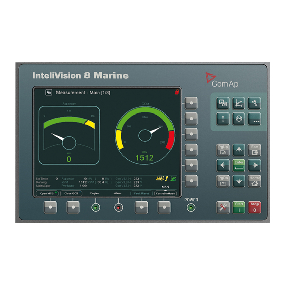
3.1 IV8 front face This chapter provides information on how to quickly find important data. To be more familiar with InteliVision 8 menu, see Operator interface on page 21 You can see InteliVision 8 front face and layout of all its buttons and LEDs in IV8 front face (page 9) Image 3.1 InteliVision 8 face... -
Page 10: How To Connect Iv8 Display To Igs-Nt Or Id Controller
Opens/closes GCB Status bar Shows permanently important values 3.2 How to connect IV8 display to IGS-NT or ID controller? InteliVision 8 can be connected to the controller via: NT terminal RS232/485 3.2.1 To connect to a Controller: 1. Press Help/Others button 2. -
Page 11: Automatic Detection
Note: It is recommended to use automatic detection only in case the communication parameters of the controller are not available. IMPORTANT: During detection phase, InteliVision 8 stops communicating with already connected controller – it is switched to initialization screen – and communication with the actual controller is lost. -
Page 12: How To Enter A Password
5. Use ↑ ↓ to go to EnterPassword field and press Enter 6. Enter password and press Enter 7. Use ↑ ↓ and confirm the password by pressing Login button Note: When you try to edit a locked setpoint the login dialog appears automatically. Image 3.4 Password dialog InteliVision 8... -
Page 13: How To View Important Values
In case you are successful logged on, the icon below appears in the upper right corner. The icon indicates that user The Best ComAp User is logged on with access level 7. 3.4 How to view important values? No matter where you are in the menu you can see all the time important values (engine speed, power,…) in the status bar at the bottom of the screen. -
Page 14: How To Change A Gen-Set Mode
1. Press ControllerMode button at the bottom of IV8 display. Available gen-set modes appear, e.g. TEST, AUT, MAN, OFF. Note: Available gen-set modes depend on the type of used application. 2. Select a mode by pressing the appropriate context button. After a while the label above ControllerMode button will change. InteliVision 8... -
Page 15: How To Change Setpoints
You can find more information about alarms inAlarmList screen (page 43). Note: When a new alarm appears the AlarmList page is displayed automatically only when the actual GUI position is Home metering screen. From the other GUI location the AlarmList button must be pressed. InteliVision 8... -
Page 16: Communication Error
3. Press Password. 4. Use ↑ ↓ to go to Users field and press Enter. 5. Use ↑ ↓ to choose a user and press Enter. 6. Use ↑ ↓ to go to NewPassword field and press Enter. InteliVision 8... -
Page 17: How To Change Display Brightness
The brightness can be adjusted in the full range of 0 % - 100 % in the both modes How to change display brightness? (page 17), How to change display brightness? (page 17). The brightness of the display can be increased/decreased by holding Esc button and repeated pressing ↑ ↓. See picture below: InteliVision 8... - Page 18 Pressing ESC + PgUp buttons or ESC + PgDn buttons switches between modes, which shall be adjusted, when dialog for changing of intensity brightness is active How to change display brightness? (page 17),How to change display brightness? (page 17). Image 3.11 Day mode brightness setting InteliVision 8...
-
Page 19: Main Icons Description
Icons at the TOP of IV Display In IGS-NT controller Figure + "The Best ComAp User" = User name Open green lock and = display is NOT locked; user is logged in 7 = a user has assigned access level 7 Display or setpoint is locked;... - Page 20 Remote communication (appears when any remote connection to controller is active) Blinking exclamation mark = a new alarm occurred. After enter of AlarmList, the exclamation stops blinking Blue ringlet = opened Green circle = closed Red circle = MCB/GCB fail InteliVision 8...
-
Page 21: Operator Interface
InteliVision 8 front face and layout of all its buttons and LEDs. Note: When you switch on InteliVision 8 display, Power LED turns on and Engine and Alarm LEDs start to blink for a while during initialization (aprx. from 35s to 1min). - Page 22 Alarm LED indication (yellow = alarm of the first level, e.g. warning, red = Alarm alarm of the second level, e.g. shutdown) Engine Engine LED indication (green = the engine is running) Opens/closes MCB Opens/closes GCB Status bar Shows permanently important values InteliVision 8...
- Page 23 Display of chosen values in graphs/real time trends Setpoints Setpoints setting AlarmList List of actuve and/or unacknownledged alarms History Display of history records Settings/info (users/passwords, communication, languages, IV and controller info, IV Help/Others settings) Image 4.3 Navigation buttons InteliVision 8...
- Page 24 Jump to Main Measurement screen Confirms a value or opens a value adjustment within setting dialogs Movement left Movement right Movement down Movement up Note: To leave the menu, use Esc, Enter or ↑ ↓ → ← buttons. InteliVision 8...
-
Page 25: Measurement Screens
Image 4.4 Context menu in Measurement screen InteliVision 8 contains 6 context buttons, which you can use directly in context menu. If context menu contains more than 6 items, you have to use PgDn and PgUp buttons to get to extended context menu. -
Page 26: Igs-Nt Standard Measurement Screens
Image 4.6 Main screen Note: What do numbers in the bracket [1/4] in the top of screen mean? The first number is the number of a screen sequence The second number is total number of screens in Measurement block. InteliVision 8... - Page 27 Image 4.7 Power screen Image 4.8 Main screen InteliVision 8...
- Page 28 Image 4.9 Gen screen Image 4.10 Synchroscope screen InteliVision 8...
- Page 29 Image 4.11 Statistics screen Image 4.12 Analog Inputs screen InteliVision 8...
-
Page 30: Id Measurement Screens
Note: What do numbers in the bracket [1/4] in the top of screen mean? The first number is the number of a screen sequence. The second number is total number of screens in Measurement block. Image 4.14 Main screen InteliVision 8... - Page 31 Image 4.15 Analog inputs screen Image 4.16 Binary 1/0 screen InteliVision 8...
- Page 32 Image 4.17 Statistics screen InteliVision 8...
-
Page 33: Trends Screen
Switches PageMode on/off (in On Mode the movement of the trend or marker is 10x PageMode On faster). The icon is displayed in top line of Trend monitoring screen. Export -> USB Single export trends to USB Import <- USB Import of trends from USB InteliVision 8... -
Page 34: Trends - Channels
Image 4.20 Channel trends settings Use ↑ ↓ buttons in the left column to select a group of values. Use → ← buttons to go to the right column, use ↑ ↓ buttons to select a certain value and press Enter. InteliVision 8... - Page 35 Use ↑ ↓ buttons to move within "Visibility column" and set by pressing Enter button in row relating to bit which should not be logged. The final selection has to be confirmed by big button in bottom of pop-up window or cancelled by pressing button. InteliVision 8...
-
Page 36: Trends - Settings
Use ↑ ↓ → ← buttons to choose Grid density. Similarly choose Sample period of trends in seconds (1 second is a minimum; 7200 second i.e. 2h is maximum). Choose button to start trends, using the Start button from Trends Context menu InteliVision 8... -
Page 37: Export/Import Of Trends
Movement of Markers is done by pressing → ←. It is possible to move only one of them. Button Enter allows switching between Markers. Note: When markers are on different screen and you want the both to have on actual screen, just switch OFF and ON Markers again. InteliVision 8... -
Page 38: Scrolling By Page
Sample period Time of saturation 12 hours and 15 min 1 min 30 days and 12 hours 120 min 3669 days Note: In case USB stick is plugged to IV8, time information is associated with USB stick free space. InteliVision 8... - Page 39 When continuous logging of trend is selected, the time information is relating to free space of connected USB storage. The maximal displayed time is 99 years. When value of available space is bigger, information “ >99 years” is displayed. Time format of available space dd:hh:mm yy:dd:hh >99 years InteliVision 8...
-
Page 40: Setpoints Screens
Setpoints groups. Scroll bar in the right side of the Setpoints Group determines position in setpoint list. The value of Setpoint can be: Strictly numerical value Text list selection Strictly text value, where text string can be edited by a user Combination of numerical and text value InteliVision 8... -
Page 41: Change Of The Numerical Value
←buttons. It means from the highest digit place to the lowest digit place and vice versa. Note: If you set the value out of limit, the field will color red and you will not be able to confirm the value. InteliVision 8... -
Page 42: Text String Selection
2. Use ↑ ↓ to go to a certain setpoint (e.g. Governor mode) and press Enter, see Text string selection on page 42 Image 4.28 String value selection 3. Use ↑ ↓ to select the string from the list and press Enter. InteliVision 8... -
Page 43: Text String Edit
AlarmList. Note: When a new alarm appears AlarmList screen is displayed automatically only when you are in Main Measurement screen. When you are in other screens, you have to press AlarmList button to display AlarmList screen. InteliVision 8... - Page 44 IV8. When the number of alarms is more than up to 16 alarms divided to two columns can be visible on screen AlarmList for IGS-NT controllers (page 43). Message from ECU (when connected) is expressed blue color. InteliVision 8...
- Page 45 Image 4.31 Alarm List – 16 alarms in AlarmList Alarm summary (taken from the left,AlarmList for IGS-NT controllers (page 43)) White number Number of active alarms Halved asterisk Sum of unacknowledged active and inactive alarms Total sum of alarms Image 4.32 Alarm summary InteliVision 8...
-
Page 46: Alarmlist For Id Controller
The left column for ID controller The right column for ECU To move between ID and ECU alarms in AlarmList use → ← buttons. Fault Reset button confirms either ID or ECU alarms. Image 4.33 ID controller alarm list InteliVision 8... -
Page 47: History Screen
(quicker movement through columns). Icon at the top of the screen indicates that PageMode On PageMode is On. History -> USB - Automatic export history to csv file to connected USB stick see Export of history on page 57 InteliVision 8... -
Page 48: Change Of An Order Of Columns
As number of items in the context menu exceeds the number of context buttons (6) it is necessary to use PgUp and PgDn buttons for navigation within the menu. This feature has been already available in Measurement or Setpoints submenu. Press Help/Others button. Help/Others screen appears: InteliVision 8... - Page 49 Image 4.36 Help/Others screen – part 1 Image 4.37 Help/Others screen – part 2 InteliVision 8...
-
Page 50: Help Context Buttons
4.6 Rules for help customization 4.6.1 How it works InteliVision 8 firmware (InteliVision8.ivp) can consist of more file types (not only InteliVision8.exe) as logo.bmp or ”hlp_xxx.txt” files are. IVP file can be created in IVProg application (from version 1.1), see IVProg from Genconfig on page 81. -
Page 51: Text Formatting Rules
Help selection priorities InteliVision 8 help searching procedure is following. First when certain language is chosen in controller it looks for help in such a language. In case it is not present it looks for help which is independent on language selection. -
Page 52: Other Important Rules
Do not use Enter to insert new line in the text file, there is a special tag for creating new line. In case you use Enter in text file (what appears in text editor as 3 new lines) there won’t be new line on InteliVision 8 screen visible, there will be just a rectangle sign. - Page 53 </font></h>Enclose text between opening tag <lt>font color="number"<gt> and closing tag <lt>/font<gt> <p>where "number" is an index of color (0 - 15).<p><br>When you press Enter twice there are following signs and there are no 2 new lines as could be expected. Image 4.38 Help programming example InteliVision 8...
-
Page 54: Initial Screen
54), there is an info bar which contains useful and important information about InteliVision 8. This information is visible on init screen before the connection between display and controller unit is established. It means you don’t need to connect to any... -
Page 55: Support Of Customized Logo
5.2 Support of customized logo A customer can use the standard InteliVision 8 logo or his own customized logo on initial screen. This logo is visible only during InteliVision initializations. Customized logo can be imported within the frame of InteliVision.ivp during firmware upgrade using IVprog (from version 1.1). -
Page 56: Features Based On Usb
InteliVision 8 is equipped by USB port on the back side, which automatically detects plug/unplug on of USB storage. When USB storage is connected to InteliVision 8 it is indicated by blue icon in the right side of upper status bar Features based on USB (page 56). -
Page 57: Export Of History
6.2 Export of history User can very easily download and save History from InteliVision 8 to USB storage. For this purpose the new item (Export->USB) was introduced in History context menu. This item is available when the USB storage is plugged in. -
Page 58: Export/Import Of Trends
When capacity of USB storage is exceeded the oldest file is deleted and saving process continues. Mode 2 saving process is working as cyclic buffer where sata is saved to one file "trends-circular.TRD" InteliVision 8... -
Page 59: Single Export Of Trends
Difference between winscope and csv format Channel definition Channel data Binary bits Start/Stop marker When exported data format is selected, progress of export is indicated in pop-up window. During export, operation, color of USB icon in upper part of screen changes to red. InteliVision 8... -
Page 60: Import Of Trd File
6.3.3 Import of TRD file It is possible to import continuously saved data back to InteliVision 8 for example after blackout and etc. In order to import data go to Trends context menu where Import <- USB item was introduced. Import operation is indicated by green color of USB icon and pop-up window with progress indicator. -
Page 61: Usb As "Login Key
6.5 USB as “login key” This feature allows that a user can log in very quickly to the InteliVision 8 with proper security level without typing of password manually. The login information is automatically loading from USB stick. The login information is saved in PASSWORD folder in file with dedicated file definition: password-[genset name].txt... - Page 62 When you plug in the USB storage with password the Login window automatically appears and after confirmation by Enter button user is logged in InteliVision 8 with proper security level. This status in indicated by green icon in upper right corner of screensee USB as “login key” on page 61.
-
Page 63: Support Of User's Pictures
6 back to Table of contents InteliVision 8 comes with very powerful feature – using user’s pictures in screen definition. This feature gives a user possibility to create screens with own pictures or to modify default screens see Support of user’s pictures on page 63, Support of user’s pictures (page... - Page 64 Image 7.1 Using user’s Picture for screen definition 1 Image 7.2 Using user’s Picture for screen definition 2 Supported picture formats: InteliVision 8...
- Page 65 Note: Pictures are NOT automatically resized on maximal size. When bigger picture is used, it will be automatically crop. The memory of InteliVision 8 is not unlimited. Amount of pictures which user can use is depended on size of of pictures. Approximately it is possible to use 5-6 pictures of maximal size for one screen.
-
Page 66: Screen Modification
8.3 Transparency attribute 8.4 Support of Tier 4 Final symbols 6 back to Table of contents InteliVision 8 measurement screens are predefined in each configuration. However if they are not a user convenient, the user can modified them. InScreen modification (page 66)you can see the example of the screen change. - Page 67 Measurement and the third button is associated with RemoteSwitch 1, which is used as toggle button. Labels on buttons are customizable. Note: The name of buttons Horn, Start, Stop is not possible to change. Note: Functions and Commands assigned to buttons in IV8 of actual archives are default. Image 8.2 User buttons InteliVision 8...
-
Page 68: Support Of Color Palette
Current version supports 255 new color plus color from previous IV8 version. All color can be chosen from color palette implemented in Screen Editor see Support of color palette on page 68. Image 8.3 Color palette InteliVision 8... -
Page 69: Transparency Attribute
8.3 Transparency attribute New attribute “transparency” was added” to Measurement objects. It means that each graphical object can have transparent background.Transparency attribute (page 69) how this parameter is possible to use. Image 8.4 Transparency InteliVision 8... -
Page 70: Support Of Tier 4 Final Symbols
8.4 Support of Tier 4 Final symbols InteliVision 8 is ready to use in projects requiring the fullfillment of the Tier 4 Final standard. InteliVision 8 supports the symbols concerned to the Tier 4 Final regulation. see Support of Tier 4 Final symbols on page Image 8.5 Tier 4 Final symbols (Illustrative Picture) -
Page 71: Installation
9.4 Modules’ address combination on CAN (IG/IS-NT, ID) 9.4.1 IGS-NT controllers and 4 InteliVisions 8 on CAN2 9.4.2 ID-DCU Marine controller and up to 8 InteliVisions 8 on CAN2 6 back to Table of contents 9.1 Terminals and dimensions Image 9.1 Terminal dimension InteliVision 8... -
Page 72: Mounting System
9.2 Mounting system Image 9.2 Mounting system 9.3 Recommended wiring Image 9.3 IG-NT wiring InteliVision 8... - Page 73 Image 9.4 IS-NT wiring Image 9.5 InteliDrive DCU wiring InteliVision 8...
-
Page 74: Id-Mobile Wiring
Image 9.6 InteliDrive – DCU Marine wiring 9.3.1 ID-Mobile wiring InteliVision 8 can be connected also to ID-Mobile. ID-Mobil has 2 communication interfaces, which can be used for communication with InteliVision 8: RS485 CAN2 Since ID-Mobile has a waterproof cover, it has not free-accessible communication ports. All ports and inputs/output are merged to 2 large waterproof connectors. -
Page 75: Modules' Address Combination On Can (Ig/Is-Nt, Id)
Image 9.8 Description of pins of ID-Mobile relating to communication with InteliVision Note: Only 2 InteliVisions 8 can be installed to CAN2 with using one ID-Mobile. Note: Only 1 InteliVision 8 can be installed on RS485. 9.4 Modules’ address combination on CAN (IG/IS-NT, ID) -
Page 76: Igs-Nt Controllers And 4 Intelivisions 8 On Can2
Modem. Each Modem address can be occupied either only with InteliVision 8 or only with Modem. It is not possible to use them simultaneously. If the third and fourth addresses have to be used by InteliVision 8, the addresses have to be enabled by the appropriate setpoints - CanAddrSwitch1 and CanAddrSwitch2. - Page 77 1.7 or newer. Image 9.10 ID-DCU Marine and 8 InteliVisions 8 on CAN2 The fourth InteliVision 8 (terminal addr. 3) has to be enabled in the same way as was described above in the chapter ID-DCU Marine controller and up to 8 InteliVisions 8 on CAN2 (page 76) Note: If it is necessary I-RD CAN can be connected to CAN2 as the fifth display.
-
Page 78: Intelivision 8 Programming
IVprog SW support 64-bit Windows Vista and Windows 7. 10.1 ActiveSync When InteliVision 8 is not connected, ActiveSync is not taking any action (except showing the grey icon in the tray). When you connect InteliVision 8 display to your PC (using USB cable type A-B) ActiveSync starts to connect. - Page 79 It is enough to press “No” for InteliVision 8 upgrade purpose and press Next. Also main ActiveSync window appears. Image 10.2 ActiveSync Main window If you need you can change the communication settings (File-> Connection Settings...).see ActiveSync on page 78.
-
Page 80: Windows Mobile Device Center (Wmdc)
Note: If you use Windows Vista, SP1 has to be installed to make the IVProg running properly. WMDC behavior is analogical to ActiveSync behavior (except you don’t have to Set Up a Partnership). Note: To see what PC software versions support IV, see Firmware and PC Software Supporting InteliVision 8 chapter. -
Page 81: Ivprog From Genconfig
10.3.1 IVProg from Genconfig Image 10.5 GenConfig and InteliVision 8 SW upgrade Image 10.6 DriveConfig and InteliVision 8 SW upgrade InteliVision 8... - Page 82 Image 10.7 IVProg main window There are several possibilities in what you can do in IVProg: Read firmware (page 83) Write firmware (page 83) Manage firmware (page 85) Read pictures (page 87) Write pictures (page 88) Manage pictures (page 89) InteliVision 8...
- Page 83 Image 10.9 Warning message relating to connection In case your PC is not connected to InteliVision 8, you should first create the connection using USB A/B cable and then you can press OK. In case the connection is already established just press OK.
- Page 84 If the chosen firmware is older than the one which is present in InteliVision 8 the following message appears: Image 10.10 Warning on old version of InteliVision 8 firmware After message confirmation, InteliVision 8 firmware is automatically backuped from InteliVision 8 to PC.
- Page 85 Image 10.13 Message noticing end of upload process Manage firmware This function allows modifying of InteliVision 8 firmware content. InteliVision firmware can consist of following files and it is up to customer to decide what files should be included in the firmware and which not. The only obligatory file which has to be present is InteliVision.exe file all the others are optional.
- Page 86 Default firmware location is the same as for firmware saving. c:\Documents and Settings\All Users\Dokuments\ComAp PC Suite\Tools\IVProg Image 10.14 Selection of firmware When firmware is chosen a new window for firmware modification appears. Image 10.15 Window for firmware modification You can see the content of the firmware which is being modified on the left side and content of your computer on the right side.
- Page 87 Read Pictures button “Save As” window appears (see the picture below) and you can choose a location where you would like to save the downloaded pictures. Image 10.16 Downloading of IVI package of pictures Name of the IVI package is automatically created and it contains information about date and time: Ivi_<YYMMDD>_<HHMMSS>.ivi. InteliVision 8...
- Page 88 (see the picture below) and you can choose a location where your IVI package is prepared. Note: Image Manager can be launched directly from Screen Editor or from IVProg. Image 10.17 Uploading of IVI package of pictures When uploading is finished correctly, following dialog appears. In other case, error dialog appears: InteliVision 8...
- Page 89 Manage pictures This function launches Picture package Manager see Manage pictures on page 89, where package of pictures can be modified. Image 10.18 Image picture Manager and Editor InteliVision 8...
-
Page 90: Ivprog And File Association
Above functions help you with managing of pictures, which are supposed to be uploaded to IV8. Picture Package Manager is possible to launch also from Screen Editor. Note: When package is read/written to IV8, InteliVision 8 has to be connected with PC with A/B USB cable. 10.3.2 IVProg and file association IVP file (firmware) and an IVI files (package of pictures) are associated with IVprog application and according to their extension corresponding function is automatically started. -
Page 91: Ivprog And Command Line
IVProg.exe -r C:\DirName\outputPicturesFilename.ivi Uploading of firmware to IV8 (IVP file) IVProg.exe -w inputFirmwareFilename.ivp Downloading of firmware from IV8 (IVP file) IVProg.exe -r C:\DirName\outputFirmwareFilename.ivp Start of HELP for IVprog command line: IVProg.exe –h Start IVProg.exe without parameter for IVProg graphical interface. InteliVision 8... -
Page 92: Technical Data
Flash memory data retention time 10 years Protection front panel IP65 95% without condensation Humidity IEC/EN 60068-2-30 11.3 Climatic, mechanical and EMC standards InteliVision 8 fulfill following standards: CE Standard conformity Low Voltage Directive: 2006/95/EC EMC directive: 2004/108/EEC InteliVision 8... - Page 93 1 min Germanische Lloyd spec., Insulation resistance VI-Part 7, §13 Electrostatic discharge EN 61000-4-2 6kV contact discharge; 8kV air discharge Radiated elmag. field EN 61000-4-3 immunity Fast low energy EN 61000-4-4 transients/bursts Slow high energy EN 61000-4-5 transient/surges InteliVision 8...
-
Page 94: Dimensions And Weight
CISPR 16-1, CISPR 16-2 from enclosure Conducted low Germanische Lloyd spec., frequency interference VI-Part 7, §20 11.4 Dimensions and weight Front panel 289,5 x 186mm Dimension Rear cover 278,60 x 175,6x33,60mm InteliVision 8 cutout 178 x 282mm Weight 1600g InteliVision 8... -
Page 95: Communication Interface
Display lifetime at least 20.000h (display will be switched off when inactive) Values Item Symbol Condition Unit Remark Min. Typ. Max. θL Φ=180°(9 o’clock) θR Φ=0°(3 o’clock) Viewing angle degree Note 1 (CR>10) θT Φ=90°(12 o’clock) θB Φ=270°(6 o’clock) Contrast ratio Normal Note 2 Luminance θ=Φ=0° cd/m² Note 3 InteliVision 8... - Page 96 Contrast ratio (CR) = Luminance measured when LCD on the "Black" state / Luminance measured when LCD on the „White" state. Note: All input terminals LCD panel must be ground while measuring the center area of the panel. The LED driving condition is IL=20mA of which each LED module is 3 LED serial. InteliVision 8...