Table of Contents
Advertisement
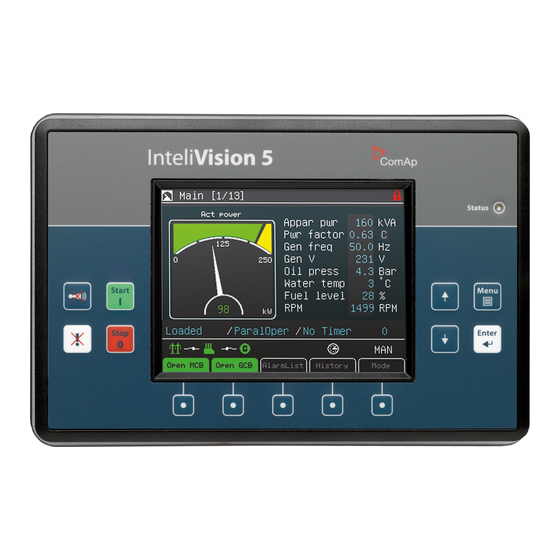
InteliVision 5, InteliVision 5 RD
InteliVision 5 Display
Controller Display Unit for InteliGen-NT, InteliSys-NT, InteliMains-NT
SW version 1.1, December 2011
Copyright © 2010 ComAp, spol. s r.o.
Written by Martina Ťopková
Prague, Czech Republic
InteliVision 5-1.1 Reference Guide ©ComAp – December 2011
ComAp, spol. s r.o.
Kundratka
2359/17, 180 00 Praha 8, Czech Republic
Tel: +420
246 012
111, Fax: +420 246 316 647
E-mail: info@comap.cz, www.comap.cz
Reference Guide
1
Advertisement
Table of Contents

Related Manuals for ComAp InteliVision 5


Summary of Contents for ComAp InteliVision 5
-
Page 1: Reference Guide
Copyright © 2010 ComAp, spol. s r.o. Kundratka 2359/17, 180 00 Praha 8, Czech Republic Written by Martina Ťopková Tel: +420 246 012 111, Fax: +420 246 316 647 Prague, Czech Republic E-mail: info@comap.cz, www.comap.cz InteliVision 5-1.1 Reference Guide ©ComAp – December 2011... - Page 2 Fast Navigation............................6 Main Icons Description........................6 Icons at the Top of InteliVision 5 Display..................6 Icons at the Bottom of InteliVision 5 Display .................. 6 Communication Error .......................... 7 How to View a Controller Status ......................8 How to View a Breaker Status ......................8 How to Control Circuits Breakers? ......................
- Page 3 Installation.............................. 38 Terminals and Dimensions........................ 38 How to Connect InteliVision 5 to IG-NTx-BB ..................39 How to Connect InteliVision 5 (Detail of InteliVision 5 Socket)............39 How to Connect InteliVision 5 to IS-NTx-BB..................40 Technical Data............................41 HW Modification ..........................41 Power Supply ............................
-
Page 4: Introduction
The same cut-out across all Comaps’ products helps InteliVision 5 to be easily used as a replacement of or alternative to IG-Display. Regardless of the size it can be also used as an alternative to IS- Display or InteliVision8. -
Page 5: Available Related Documentation
Firmware – InteliVision 5 is supported from following versions: Mhx file IS-NT-2.6 IG-NT-2.6 IM-NT-2.9 PC Software – InteliVision 5 is supported from following versions: PC Software GenConfig-2.6 InteliMonitor-2.6 Installation Package – InteliVision 5 is supported from following versions: Installation Package IGS-NT-Install-Suite-2.6... -
Page 6: Fast Navigation
This chapter provides information on how to quickly find important data. To be more familiar with InteliVision 5 menu, see Operator Interface chapter. Notation : InteliVision 5 and InteliVision 5 RD differ only by HW modification (see chapter Modification ). All below described features, setting and programming Main Icons Description Icons at the Top of InteliVision 5 Display Terminal is locked;... -
Page 7: Communication Error
When the communication between unit and display is fixed, the red stripe disappears and InteliVision 5 initializes communication with the unit. Hint: The control unit is identified by InteliVision 5 and only valid numbers of terminal addresses are displayed. For the maximum number of connected InteliVision 5 see How many InteliVisions 5 can be used? InteliVision 5-1.1 Reference Guide ©ComAp –... -
Page 8: How To View A Controller Status
(when no colour background is used) and dark green or dark red when breaker status is highlighted. How to Control Circuits Breakers? Breakers can be controled in MAN mode only. Breaker control button is placed in bottom part of InteliVision 5 display. See picture bellow: InteliVision 5-1.1 Reference Guide ©ComAp – December 2011... -
Page 9: How To Connect Intelivision 5 To Igs-Nt
When InteliVision 5 is connected to IS-NTC BB, there can be connected up to 3 IV5. When “terminal Adr.“ dialog is chose, all terminals are automatically detected . Available NT terminal addresses are displayed by green color. -
Page 10: How To Enter A Password
How to Enter a Password? To enter a controller password: 1. Press Menu button. 2. Use ↑ or ↓ to choose Help/Others and press Enter 3. Use ↑ or ↓ to choose Users/Password menu item InteliVision 5-1.1 Reference Guide ©ComAp – December 2011... - Page 11 "Controller is locked. Try entering correct password after X min" is displayed. Message informs about time remaining for unlocking of controller. The time in message is not actualized. For actual time, user should open login dialog again. InteliVision 5-1.1 Reference Guide ©ComAp – December 2011...
-
Page 12: How To Change A Password
2. Use ↑ or ↓ to choose Help/Others, press Enter 3. Use ↑ or ↓ to choose Users/Password menu item and press Enter 4. Use ↑ or ↓ to choose Logout and press Enter. InteliVision 5-1.1 Reference Guide ©ComAp – December 2011... -
Page 13: How To Change A Gen-Set Mode
2. Use ↑ or ↓ to choose menu item AlarmList and press Enter. 3. Or use context button AlarmList to jump directly to Alarm list. Hint: In the first measurement screen controller will jump to the alarm list immediately when any alarms occurs. InteliVision 5-1.1 Reference Guide ©ComAp – December 2011... -
Page 14: How To Change Setpoints
2. Use ↑ or ↓ to choose Setpoints item, press Enter 3. Use ↑ or ↓ to choose required setpoints group and press Enter. 4. Use ↑ or ↓ to choose requested setpoint and press Enter. InteliVision 5-1.1 Reference Guide ©ComAp – December 2011... -
Page 15: How To Reprogram Intelivision 5
How to edit setpoints see Setpoints Screens chapter. How to Reprogram InteliVision 5? To reprogram InteliVision 5 use GenConfig PC SW. 1. Run GenConfig 2. Connect communication cable (appropriate type according to the module used) between the controller and PC. -
Page 16: How To Change Display Brightness
Two modes are available in InteliVision 5.To switch between Day or Night mode hold Menu button only. Pictogram for day or night appears on the screen. To change day or night brightness intensity: 1. Hold Menu button until day / night mode on the screens appear 2. -
Page 17: Operator Interface
Operator Interface This chapter provides general information on how to operate the InteliVision 5 display. This manual is intended for everybody who is concerned with operation and controls of the gen-set. LED and Buttons 1. Status Status LED indication (green = InteliVision 5 is running) 2. -
Page 18: Context Buttons
4. Horn reset Deactivates the horn (audible alarm) Hint: Start and Stop buttons work in MAN or SEM mode only. START and STOP buttons are independent on the InteliVision 5 screen, menu or sub-menu. InteliVision 5-1.1 Reference Guide ©ComAp – December 2011... -
Page 19: Measurement Screens
On Measurement screen you can see and check various values. Measurement screens appear after the InteliVision 5 and controller are powered up and initialize sequence disappears. The first Measurement screen always appears when no user activity is captured during fifteen minutes. - Page 20 3. Mains overview - Mains 4. Power overview – Power 5. Alternator overview - Gen-set power InteliVision 5-1.1 Reference Guide ©ComAp – December 2011...
- Page 21 6. Synchroscope 7. Statistics values – Statistics InteliVision 5-1.1 Reference Guide ©ComAp – December 2011...
- Page 22 8. Control Unit Analog Inputs (internal values) 9. Connected analogue values - Analog Inputs InteliVision 5-1.1 Reference Guide ©ComAp – December 2011...
- Page 23 Other screens with ECU values, analogue or binary inputs/outputs can follow. It depends on the controller configuration. Hint Use ↑ or ↓ to scroll the screens. Screens could be hidden or the order of the screens could be modified by users. InteliVision 5-1.1 Reference Guide ©ComAp – December 2011...
-
Page 24: Setpoints Screens
3. Use → or ← buttons to go to a certain position of the field and use ↑ or ↓ buttons to change the value. Then use Enter button to confirm new value. InteliVision 5-1.1 Reference Guide ©ComAp – December 2011... -
Page 25: String Selection
2. Use arrows ↑ or ↓ to go to a certain set-point (e.g. Gen-set name) and press Enter button, see picture below: Actual position in characters list 3. Use ↑ or ↓ buttons to select the character and → ← buttons for the next position and press Enter button. InteliVision 5-1.1 Reference Guide ©ComAp – December 2011... -
Page 26: Time And Date Edit
2. Use arrows ↑ or ↓ to go to a certain set-point (e.g. PeakAutS/S del) and press Enter button, see picture below: 3. Use ↑ or ↓ buttons to select the number, → or ← for the next position or Go Up/Go Down context buttons and press Enter button. InteliVision 5-1.1 Reference Guide ©ComAp – December 2011... -
Page 27: Unauthorized Access Message
Unauthorized access message Setpoints can be locked for unauthorized edit. If a user does not have permission to edit certain setpoints, "Access Denied" pop-up message is displayed (see figure below). InteliVision 5-1.1 Reference Guide ©ComAp – December 2011... -
Page 28: Alarmlist Screen
Where to Find Alarms: 1. To go to AlarmList screen, press AlarmList context button or Menu button and choose AlarmList. Sum of all alarms Sum of unacknowledged active and inactive alarms Number of active alarms InteliVision 5-1.1 Reference Guide ©ComAp – December 2011... - Page 29 Alarm written in black background- Inactive alarm (resolved - visible only when unacknowledged) Alarm activated with analogue value Second level alarm First level alarm Alarm activated with binary inputs First level alarm Second level alarm InteliVision 5-1.1 Reference Guide ©ComAp – December 2011...
-
Page 30: History Screen
History depends on a controller configuration. History is erased when controller configuration is changed and reprogrammed. For more information how to change history columns see GenConfig Reference Guide or GenConfig context help. InteliVision 5-1.1 Reference Guide ©ComAp – December 2011... -
Page 31: Help/Others Menu
4. Use ↑ or ↓ to choose correct language and press Enter Hint: InteliVision 5 will reboot when the language is changed. This reboot does not affect control unit. User/Password When user is signed into the controller he can choose a user from the list of users (every user has got certain rights) and then password has to be used. -
Page 32: Communication
Communication To see information on how to connect InteliVision 5 display to a controller, go to How to Connect IV5 display to IGS-NT? sub-chapter. Controller info To see information about the control unit see Controller info page. See the picture below: Modules info Modules info is the screen where all connected modules can be seen, e.g. -
Page 33: Iv5 Info
IV5 Info Information about the InteliVision 5 properties can be seen in IV info screen. See the picture below: IV5 Settings Backlight Time settings allow to switch off display backlight (Standby Mode is pplied). Backlight time is switched off, when time in parameter “backlight time” lefts. The parameter is based on the time from 1 to 240 minutes or never. - Page 34 The Service screen is defined in Screen editor SW or via xml description. Screen Editor is easy way how to Drag&Drop modify screens in InteliVision 5. Screen editor is available as a part of Genconfig 2.6 and higher. InteliVision 5-1.1 Reference Guide ©ComAp – December 2011...
-
Page 35: Other Features
Other features User buttons The user has possibility to assign various functions of SoftKeys buttons - buttons on the bottom of Intelivision 5 (see Chyba! Nenalezen zdroj odkazů.). Different functions can be assigned to any button of any screen. Pre-defined functions •... -
Page 36: Unauthorized Access Message
SW version) to log into the controller, the controller is automatically locked for next login. When the controller is locked and user tries to login into the controller, message (see Figure 3). InteliVision 5-1.1 Reference Guide ©ComAp – December 2011... -
Page 37: Change Of All Label Color
From 1.1 version the color of all texts and values was changed to be text better readable also from angles. The text color is white and value color is aqua. See texts and values on right side of figure below. InteliVision 5-1.1 Reference Guide ©ComAp – December 2011... -
Page 38: Installation
Installation Terminals and Dimensions InteliVision 5-1.1 Reference Guide ©ComAp – December 2011... -
Page 39: How To Connect Intelivision 5 To Ig-Ntx-Bb
How to Connect InteliVision 5 to IG-NTx-BB How to Connect InteliVision 5 (Detail of InteliVision 5 Socket) InteliVision 5-1.1 Reference Guide ©ComAp – December 2011... -
Page 40: How To Connect Intelivision 5 To Is-Ntx-Bb
How to Connect InteliVision 5 to IS-NTx-BB InteliVision 5-1.1 Reference Guide ©ComAp – December 2011... -
Page 41: Technical Data
0,7A at 8 VDC voltage Hint: InteliVision 5 should be use with the same battery as the control unit. When external battery is needed because of long wiring and etc.. InteliVision 5 RD is recommended to use. Operating Conditions Operating temperature -40...+70... -
Page 42: Communication Interface
Maximal distance 1000m (only Remote Display) Speed up to 57.6kBd LCD Display 5.7" colour TFT display with resolution of 320 × 240 pixels LCD display active area dimension 115,2x86,4mm Pixel size 0.120(W) x 0.360(H) mm InteliVision 5-1.1 Reference Guide ©ComAp – December 2011... -
Page 43: List Of Possible Events
RS485 line is too long. Screen template missing Error Unsupported controller firmware, missing InteliVision 5 support. Screen template version Error Unsupported controller screen. InteliVision 5 firmware has to be updated. Font not valid Error Corrupted display font. Font programming was not done properly.