Advertisement
Quick Links
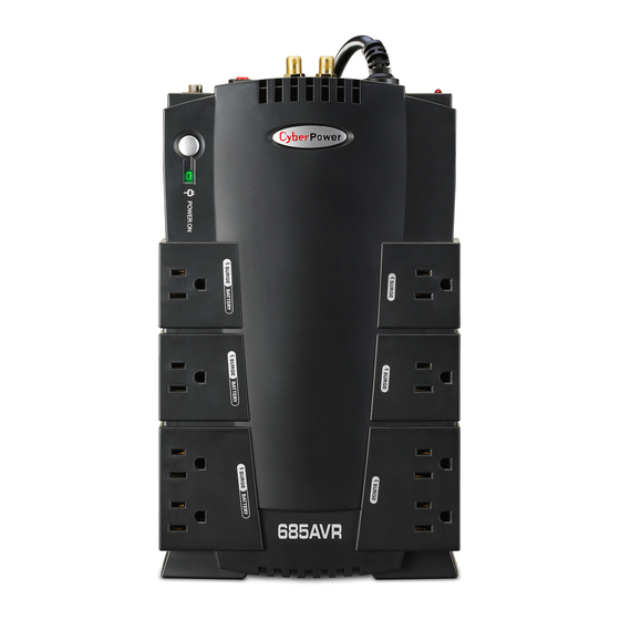
CP685AVR-G / CP825AVR-G
User's Manual
IMPORTANT SAFETY WARNINGS
(SAVE THESE INSTRUCTIONS)
This manual contains important safety instructions. Please read and follow all instructions carefully during installation and operation of the unit.
Read this manual thoroughly before attempting to unpack, install, or operate your UPS.
CAUTION! To prevent the risk of fire or electric shock, install in a temperature and humidity controlled indoor area free of conductive
contaminants. (Please see specifications for acceptable temperature and humidity range).
CAUTION! To reduce the risk of electric shock, do not remove the cover except to service the battery. There are no user serviceable parts
inside except for battery.
CAUTION! Hazardous live parts inside can be energized by the battery even when the AC input power is disconnected.
CAUTION! The UPS must be connected to an AC power outlet with fuse or circuit breaker protection. Do not plug into an outlet that is not
grounded. If you need to de-energize this equipment, turn off and unplug the unit.
CAUTION! To avoid electric shock, turn off the unit and unplug it from the AC power source before servicing the battery or installing a computer
component.
CAUTION! To reduce the risk of fire, connect only to a circuit provided with 20 amperes maximum branch circuit over current protection in
accordance with the National Electric Code, ANSI/NFPA 70.
DO NOT USE FOR MEDICAL OR LIFE SUPPORT EQUIPMENT! CyberPower Systems does not sell products for life support or medical
applications. DO NOT use in any circumstance that would affect, operation, safety of any life support equipment or with any medical
applications or patient care.
DO NOT USE WITH OR NEAR AQUARIUMS! To reduce the risk of fire or electric shock, do not use with or near an aquarium. Condensation
from the aquarium can cause the unit to short out.
INSTALLING YOUR UPS SYSTEM
UNPACKING
Inspect the UPS upon receipt. The box should contain the following:
®
(1) UPS unit; (1) User's manual; (1) PowerPanel
Personal Edition software CD; (1) USB device cable; (1) Telephone cable; (1) Warranty
registration card; (1) Coaxial Cable
WHAT IS AVR?
The CP685AVR-G / CP825AVR-G provide complete power protection from
utility power that is not always consistent. The CP685AVR-G / CP825AVR-G
feature 890 Joules / 1030 Joules of surge protection, and provide long lasting
battery backup during power outages. The CP685AVR-G / CP825AVR-G
ensure consistent power to your computer system and include software that
will automatically save your open files and shutdown your computer system
during a utility power loss.
AUTOMATIC VOLTAGE REGULATOR
The CP685AVR-G / CP825AVR-G stabilize utility power voltage levels that
can be inconsistent. The incoming utility power may be damaging to
important data files and hardware, but with Automatic Voltage Regulation, the
computer will not experience damaging voltage levels. An Automatic Voltage
Regulator automatically increases low or decreases high voltage to a
consistent, computer safe 110v/120v. The unit's powerful battery will provide
power only if the incoming voltage drops below 90v or increases above 140v.
SYSTEM FUNCTIONAL BLOCK DIAGRAM
EMI Filter
Surge
Input
Suppressor
Normal Mode
Battery Mode
HOW TO DETERMINE THE POWER REQUIREMENTS OF YOUR EQUIPMENT
1. Ensure that the equipment plugged into the outlet does not exceed the UPS unit's rated capacity (685VA/390W for CP685AVR-G,
825VA/450W for CP825AVR-G). If the rated capacities of the unit are exceeded, an overload condition may occur and cause the UPS unit
to shut down or the circuit breaker to trip.
2. There are many factors that can affect the amount of power that your computer system will require. It is suggested that the load you will be
placing on the outlet not exceed 80% of the unit's capacity.
HARDWARE INSTALLATION GUIDE
1. Your new UPS may be used immediately upon receipt. However, recharging the
battery for at least 8 hours is recommended to ensure that the battery's maximum
charge capacity is achieved. A loss of charge may occur during shipping and
storage. To recharge the battery, simply leave the unit plugged into an AC outlet.
2. With the UPS unit off and unplugged, connect your computer, monitor, and any other
peripherals requiring battery backup into the battery power supplied outlets. Plug
your other peripheral equipment (printer, scanner, speakers) into the full-time surge protection outlets. DO NOT plug a laser printer, paper
shredder, copier, space heater, vacuum, sump pump or other large electrical device into battery and surge protected outlets. The
power demands of these devices will overload and possibly damage the unit.
3. To protect a network connection from surges, connect a network cable into the IN jack of the UPS. Then connect
a network cable from the OUT jack on the UPS to the network device.
4. Plug the UPS into a 2 pole, 3 wire grounding receptacle (wall outlet). Make sure the wall branch outlet is
protected by a fuse or circuit breaker and does not service equipment with large electrical demands (e.g. air
conditioner, refrigerator, copier, etc...). The warranty prohibits the use of extension cords, outlet strips, and surge strips.
5. Press the power switch to turn the unit on. The power on indicator light will illuminate and the unit will "beep".
6. If an overload is detected, an audible alarm will sound and the unit will emit one long beep. To correct this, turn the UPS off and unplug at
least one piece of equipment from the battery power supplied outlets. Make sure the circuit breaker is depressed and then turn the UPS on.
7. To maintain optimal battery charge, leave the UPS plugged into an AC outlet at all times.
8. To store your UPS for an extended period, cover it and store with the battery fully charged. While in storage recharge the battery every three
months to ensure battery life.
K01-0000064-00
AVR
Output
Charger
Inverter
AC/DC
Battery
BASIC OPERATION
DESCRIPTION
④
Power On Indicator
This LED is illuminated when the utility power is normal and the UPS outlets are providing power, free of surges and spikes.
Electrical Wiring Fault Indicator
⑤
This LED indicator will illuminate to warn the user that a wiring problem exists, such as bad ground, missing ground or reversed wiring. If
this is illuminated, it is recommended to disconnect all electrical equipment from the outlet and have an electrician verify the outlet is
properly wired. The unit will not provide surge protection without being plugged into a grounded and properly wired wall outlet.
Communication Protection Ports
⑥
Communication protection ports will protect any standard modem, fax, telephone line, network or Ethernet connection (RJ11/RJ45).
⑦
Circuit Breaker
Located on the side of the UPS, the circuit breaker serves to provide overload and fault protection.
USB Port and DB-9 Contact Closure Port to PC
⑧
The ports allow connection and communication between the USB or DB-9 port on the computer and the UPS unit. The UPS
®
communicates its status to the PowerPanel
Personal Edition software. The DB9 interface is compatible with Power Management
®
provided by Windows
NT/2000/2003/XP and the USB interface is compatible with the Power Management provided by Windows Vista, OS
X, and Linux..
Note: Only one of the ports, USB or DB-9, can be used to communicate with your computer at one time.
®
Note: To install PowerPanel
Personal Edition Software the computer will need Microsoft
Note: If using the DB-9 port, users need to order the standard RS-232 cable. If you have any questions, email CyberPower
technical support for help.
tech@cyberpowersystems.com
Outlets Designed for AC Adapters
⑨
The unit has four outlets spaced to allow AC power adapter blocks to be plugged into the UPS without blocking adjacent outlets.
Coax/Cable/DSS Surge Protection
⑩
The Coax/Cable/DSS surge protection ports will protect any cable modem, CATV converter, or DSS receiver.
REPLACING THE BATTERY
Replacement of batteries located in an OPERATOR ACCESS AREA.
1.
When replacing batteries, replace with the same number of the following battery: BP8-12 / BB for CP685AVR-G; HR1234W / BB for
CP825AVR-G.
2.
CAUTION! Risk of Energy Hazard, 12 V, maximum 8(BP8-12 for CP685AVR-G) or 9(HR1234W for CP825AVR-G) Ampere-hour battery.
Before replacing batteries, remove conductive jewelry such as chains, wrist watches, and rings.
3.
CAUTION! Do not dispose of batteries in a fire. The batteries may explode;
4.
CAUTION! Do not open or mutilate batteries. Released material is harmful to the skin and eyes. It may be toxic.
CAUTION - RISK OF EXPLOSION IF BATTERY IS REPLACED BY AN INCORRECT TYPE. DISPOSE OF USED BATTERIES ACCORDING
TO LOCAL REGULATIONS.
TO REPLACE THE BATTERY
1.
Turn off and unplug all connected equipment.
2.
Unplug it from the AC power source.
3.
Turn the UPS upside down.
4.
Remove the 1 retaining screw.
5.
Slide the battery compartment cover completely off of the unit.
6.
Remove the battery from the compartment.
7.
Disconnect the battery wires from the battery.
8.
Install the replacement battery by connecting the red wire and black wire to the positive (+) and negative (-) terminal of the battery.
9.
Put the battery back into the compartment.
10. Slide back the battery compartment cover and tighten the retaining screw.
11. Charge the unit for 4 – 8 hours to fully charge the battery.
REMINDER: Batteries are considered HAZARDOUS WASTE and must be disposed of properly. Most retailers that sells lead-acid batteries
collects used batteries for recycling, as required by local regulations.
TROUBLE SHOOTING
Problem
Possible Cause
Full-time surge protection outlets
stop providing power to
Circuit breaker has tripped due to an
equipment. Circuit breaker
overload.
button is projecting from the side
of the unit.
Battery not fully charged.
The UPS does not perform
expected runtime.
Battery is worn out.
The on/off switch is designed to
prevent damage by rapidly turning it
off and on.
The unit is not connected to an AC
outlet.
The UPS will not turn on.
The battery is worn out.
Mechanical problem.
The USB / serial cable is not
connected.
The USB / serial cable is connected
to the wrong port.
®
PowerPanel
Personal Edition is
inactive (all icons are gray).
The unit is not providing battery
power.
The serial cable is not the cable that
was included with the UPS unit.
Additional troubleshooting information can be found at
www.cyberpowersystems.com/support.htm
Battery and Surge Protected Outlets
①
The unit has four battery powered/surge suppression outlets for connected
equipment to ensure temporary uninterrupted operation of your equipment
during a power failure. ( DO NOT plug a laser printer, paper shredder,
copier, space heater, vacuum, sump pump or other large electrical
device into battery and surge protected outlets. The power demands
of these devices will overload and possibly damage the unit.)
②
Full-Time Surge Protection Outlets
The unit has four surge suppression outlets which are always on.
Power Switch
③
Press the power button to turn the UPS ON or OFF.
○
Internet Explore 6.0 or higher installed.
R
Solution
Turn the UPS off and unplug at least one piece of equipment.
Wait 10 seconds, reset the circuit breaker by depressing the
button, and then turn the UPS on.
Recharge the battery by leaving the UPS plugged in.
Contact CyberPower Systems about replacement batteries at
tech@cyberpowersystems.com
Turn the UPS off. Wait 10 seconds and then turn the UPS on.
The unit must be connected to a 110/120v 60Hz outlet.
Contact CyberPower Systems about replacement batteries at
tech@cyberpowersystems.com
Contact CyberPower Systems at
tech@cyberpowersystems.com
Connect the USB / serial cable to the UPS unit and an open
USB / serial port on the back of the computer. You must use
the cable that came with the unit.
Check the back of the computer for an additional USB / serial
port. Move the cable to this port.
Shutdown your computer and turn the UPS off. Wait 10
seconds and turn the UPS back on. This should reset the unit.
If you are using a serial cable you must use a CyberPower serial
cable. If you need this cable please contact technical support.
tech@cyberpowersystems.com
Advertisement

Subscribe to Our Youtube Channel
Related Manuals for CyberPower CP685AVR-G


Summary of Contents for CyberPower CP685AVR-G
-
Page 1: Basic Operation
REPLACING THE BATTERY Replacement of batteries located in an OPERATOR ACCESS AREA. When replacing batteries, replace with the same number of the following battery: BP8-12 / BB for CP685AVR-G; HR1234W / BB for CP825AVR-G. CAUTION! Risk of Energy Hazard, 12 V, maximum 8(BP8-12 for CP685AVR-G) or 9(HR1234W for CP825AVR-G) Ampere-hour battery. -
Page 2: Technical Specifications
Limited Warranty and Connected Equipment Guarantee Read the following terms and conditions carefully before using the CyberPower CP685AVR-G / CP825AVR-G (the “Product”). By using the Product you consent to be bound by and become a party to the terms and conditions of this Limited Warranty and Connected Equipment Guarantee (together referred to as this “Warranty”).
Need help?
Do you have a question about the CP685AVR-G and is the answer not in the manual?
Questions and answers