Advertisement
Quick Links
Battery Replacement
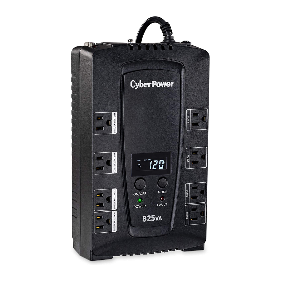
Intelligent LCD Series, AVR Series
MODEL: CP600LCD, CP825LCD, CP800AVR, CP685AVR-G,
CP825AVR-G, CP685AVRLCD-G, CP825AVRLCD-G,
AVRG750U, AVRG900U, AVRG750LCD, AVRG900LCD
1
2
1. Place the UPS on its top and remove the retaining screw (figure 1).
2. Slide the battery compartment cover completely off of the unit (figure 2).
3. Remove the battery from the compartment and disconnect the battery
wires from the battery. Install the replacement battery by connecting the
red wire to the positive (+) terminal and the black wire to the negative (-)
terminal of the battery. (figure 3)
4. Slide the battery compartment cover over the battery and tighten the
retaining screw.
5. Charge the unit for 4 – 8 hours to ensure the UPS performs expected
runtimes.
MODEL: CP850AVRLCD, CP1000AVRLCD
1
2
1. Place the UPS on its side and locate the battery compartment cover on
the bottom of the UPS. Remove the four (4) retaining screws and pull
the battery compartment cover off the UPS (figure 1 & 2).
2. Remove the battery from the compartment and disconnect the battery
wires from the batteries. Install the replacement batteries by connecting
the red wire and black wire to the same color wires from the battery
pack. Put the battery pack into the compartment (figure 3).
3. Slide the battery compartment cover over the battery and tighten the
retaining screw. Charge the unit for 4 – 8 hours to ensure the UPS
performs expected runtimes.
1
Smart APP SINEWAVE Series
MODEL: PR750LCD
1
2
3
4
1. Remove the front panel of the UPS.
2. Pull out both round knobs and remove the battery compartment cover
completely off of the unit.
3. Remove the batteries from the compartment.
4. Disconnect the battery wires from the batteries.
5. Install the replacement batteries by connecting the wire bundle
(composed of one red wire and one black wire) to the connector from
the battery pack. Put the batteries back into the compartment.
6. Re-install the battery compartment cover and push both round knobs
back into place. Put the front panel back on the UPS.
7. Connect to AC power and charge the new batteries for up to 16 hours
to insure a full charge.
MODEL: PR1000LCD
1
3
1. Remove the front panel of the UPS.
2. Remove two screws from the battery compartment cover and slide the
cover completely off of the unit.
3. Remove the batteries from the compartment. Disconnect the battery
wires from the batteries.
4. Install the replacement batteries by connecting the wire bundle
(composed of one red wire and one black wire) to the connector from
the battery pack.
5. Put the batteries back into the compartment. Re-install the battery
compartment cover and tighten the retaining screws. Put the front panel
back on the UPS.
6. Connect to AC power and charge the new batteries for up to 16 hours
to insure a full charge.
4
AVR Series
MODEL: CP900AVR, CP1200AVR, CP1500AVRT,
CP1285AVRLCD, CP1350AVRLCD, CP1500AVRLCD
1
4
3
1. Place the UPS on its side to locate and remove the front panel retaining
screws from the bottom of the UPS.
2. Slide the cover (front panel) towards the bottom of the UPS.
3. Remove it from the unit.
4. Disconnect the cable located at the top of the cover.
5. Disconnect the battery wires from the batteries.
6. Remove the batteries from the compartment.
7. Install the replacement batteries by connecting the red and black wires
to the same color wires from the battery pack. Put the battery pack
back into the compartment.
8. Replace the battery compartment cover and tighten the retaining screw.
Charge the unit for 4-8 hours to ensure the UPS performs expected
runtimes.
Smart APP Intelligent LCD Series
MODEL: OR500LCDRM1U, OR700LCDRM1U, OR1000LCDRM1U,
OR1500LCDRM1U
1
3
1. Remove the right side front panel.
2. Remove the three retaining screws for the cable protection cover and
remove the cover.
3. Disconnect the black and red cable.
4. Remove the one retaining screw holding the battery pack in place.
5. Remove the battery pack.
6. Install the new battery pack. Assemble the screws, cover, cable and
front panel in the reverse order of the previous steps. Charge the unit
for 4-8 hours to ensure the UPS performs expected runtimes.
MODEL: PR1500LCD
1
1. Remove the front panel of the UPS.
2. Remove two screws from the battery compartment cover and slide the
cover completely off of the unit.
3. Remove the batteries from the compartment. Disconnect the battery
wires from the batteries.
4. Install the replacement batteries by connecting the wire bundle
(composed of one red wire and one black wire) to the connector from
the battery pack.
5. Put the batteries back into the compartment. Re-install the battery
compartment cover and tighten the retaining screws. Put the front panel
back on the UPS.
6. Connect to AC power and charge the new batteries for up to 16 hours
to insure a full charge.
MODEL: PR2200LCD, PR3000LCD
1
2
1. Remove the front panel of the UPS and two screws from the battery
4
compartment cover and slide the cover completely off of the unit.
2. Pull out the battery pack on the outside from the compartment.
Disconnect the battery connector from the batteries.
3. Before removing the battery pack on the inside, unlock the cable tie and
pull out the battery wires. Disconnect the battery connector from the
batteries.
4. Install the replacement battery pack on the inside by connecting the
wire bundle connector (composed of one red wire and one black wire)
to the connector from the battery pack. Lock the battery wires back
with the cable tie.
5. Install the replacement batteries on the outside by connecting the wire
bundle connector (composed of one red wire and one black wire) to the
connector from the battery pack. Put the battery pack on the outside
back into the compartment.
6. Re-install the battery compartment cover and tighten the retaining
screws and put the front panel back on the UPS.
7. Connect to AC power and charge the new batteries for up to 16 hours
to insure a full charge.
Note: The battery pack on the outside has a fuse, while the battery pack
on the inside does not.
2
3
5
6
2
3
4
5
2
2
3
4
2
3
4
5
MODEL: OR1500LCDRM2U, OR2200LCDRM2U,
OR1500LCDRTXL2U, OR2200LCDRTXL2U
1
2
4
5
1. Remove the right side front panel.
2. Remove the three retaining screws for the cable protection cover and
remove the cover.
3. Remove the two retaining screws from the cable connectors.
4. Disconnect the black and red cable.
5. Remove the four retaining screws holding the battery pack in place.
6. Remove the battery pack.
7. Install the new battery pack. Assemble the screws, cover, cable and
front panel in the reverse order of the previous steps. Charge the unit
for 4-8 hours to ensure the UPS performs expected runtimes.
MODEL: CPS1500AVR
1
2
WARNING
WARNING
BATT
USING
BATTERY
BATT
BATTERY
USING
LOAD
AVR
LOAD
AVR
ON
POWER
POWER
ON
4
WARNING
BATT
USING
BATTERY
LOAD
POWER
AVR
ON
1. Remove the right side front panel.
2. Remove the two retaining screws for the cable protection cover and
remove the cover.
3. Disconnect the black and red cable.
4. Remove the four retaining screws holding the battery pack in place.
5. Remove the battery pack.
6. Install the new battery pack. Assemble the screws, cover, cable and
front panel in the reverse order of the previous steps. Charge the unit
for 4-8 hours to ensure the UPS performs expected runtimes.
3
MODEL: PR750LCDRM1U, PR1000LCDRM1U
1
2
4
5
1. Remove the right side front panel.
2. Remove the two retaining screws for the cable protection cover and
remove the cover.
3. Disconnect the black and red cable.
4. Remove the one retaining screw holding the battery pack in place.
5. Remove the battery pack.
6. Install the new battery pack. Assemble the screws, cover, cable and
front panel in the reverse sequence of the above steps. Charge the unit
for 4-8 hours to ensure the UPS performs expected runtimes.
MODEL: PR1500SWRM2U, PR2200SWRM2U
1
2
WARNING
WARNING
BATT
USING
BATTERY
BATT
BATTERY
USING
LOAD
ON
AVR
POWER
LOAD
ON
POWER
AVR
4
5
WARNING
BATT
USING
BATTERY
LOAD
AVR
ON
POWER
1. Remove the right side front panel.
2. Remove the two retaining screws for the cable protection cover and
remove the cover.
3. Disconnect the black and red cable.
4. Remove the four retaining screws holding the battery pack in place.
5. Remove the battery pack.
6. Install the new battery pack. Assemble the screws, cover, cable and
front panel in the reverse order of the previous steps. Charge the unit
for 4-8 hours to ensure the UPS performs expected runtimes.
6
3
6
3
WARNING
BATT
USING
BATTERY
LOAD
AVR
POWER
ON
5
WARNING
BATT
BATTERY
USING
LOAD
POWER
AVR
ON
3
3
WARNING
BATT
USING
BATTERY
LOAD
AVR
ON
POWER
WARNING
BATT
USING
BATTERY
LOAD
AVR
ON
POWER
Advertisement

Related Manuals for CyberPower CP825LCD


Summary of Contents for CyberPower CP825LCD
-
Page 1: Battery Replacement
Battery Replacement CP1285AVRLCD, CP1350AVRLCD, CP1500AVRLCD OR1500LCDRTXL2U, OR2200LCDRTXL2U Intelligent LCD Series, AVR Series MODEL: CP600LCD, CP825LCD, CP800AVR, CP685AVR-G, CP825AVR-G, CP685AVRLCD-G, CP825AVRLCD-G, AVRG750U, AVRG900U, AVRG750LCD, AVRG900LCD 1. Remove the right side front panel. 2. Remove the three retaining screws for the cable protection cover and 1. - Page 2 1. Remove the case screw. Cyber Power Systems, Inc. 2. Open the battery cover. 3. Loosen the battery strap. www.cyberpower.com 4. Disconnect battery cable connector to remove battery. 1. Remove the battery cover. 5. Replace with new battery and re-connect the battery connector.