Table of Contents
Advertisement
Quick Links
• When connecting the ACC conversion cable (OPC-599)
!3
Connect to ACC socket
o !0 !1 !2
t y u i
q w e r
D
DATA2 socket information
DATA2
PIN No.
1
2
q w
e
r
y
t
3
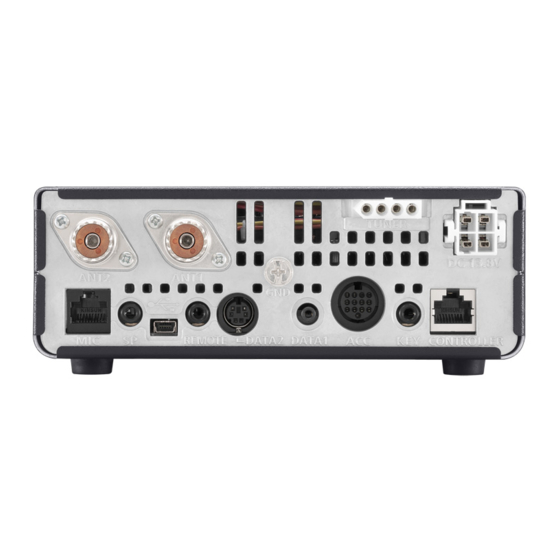
Rear panel view
4
5
6
D
Microphone connector information
MIC
PIN No.
1
2
3
4
8
7
6
5
4
3
2
1
5
Rear panel view
6
7
8
You can change this setting in "MIC AF Out" of the "Function" Set mode. (p. 6-6)
*
1
> Function > MIC AF Out
SET
ACC 1
q FSKK
w GND
e HSEND
r MOD
NAME
DESCRIPTION
Input terminal for data transmit.
DATA IN
( 1200 bps: AFSK/
9600 bps: G3RUH, GMSK)
Common ground for DATA IN, DATA
GND
OUT and AF OUT.
PTT terminal for packet operation.
PTT
Connect to ground to activate the
transmitter.
Data out terminal for 9600 bps opera-
DATA OUT
tion only.
Data out terminal for 1200 bps opera-
AF OUT
tion only.
Squelch out terminal. This pin is
grounded when the transceiver re-
ceives a signal which opens the
squelch.
SQL
• To avoid interfering transmissions,
connect squelch to the TNC to inhibit
transmission when squelch is open.
• Keep RF gain at a normal level, other-
wise a "SQL" signal will not be output.
NAME
8 V
+8 V DC output.
MIC U/D Frequency Up/Down
HM-151 connection
M8V SW
Ground to indicate the HM-151 is connected.
When the HM-151 is not connected; outputs an AF.*
PTT
PTT input
MIC E
Microphone ground
MIC
Microphone input
GND
Ground
DATA IN
When the HM-151 is connected; HM-151 data input
SQL SW When the HM-151 is not connected; Squelch switch
ACC 2
2
5
4
3
1
8
6
7
t AF
y SQLS
u 13.8 V
i ALC
Input level (1200 bps):
Input level (9600 bps):
Input voltage (High):
Input voltage (Low):
Output impedance:
Output level:
Output impedance:
Output level:
SQL open:
SQL closed:
DESCRIPTION
1-17
PANEL DESCRIPTION
2
5
4
3
1
6
7
q 8 V
t ALC
w GND
y VSEND
e HSEND
u 13.8 V
r BAND
SPECIFICATIONS
100 mV
0.2 to 0.5 Vp-p
———
2.0 V to 20.0 V
–0.5 V to +0.8 V
10 k˘
1.0 Vp-p
4.7 k˘
100–300 mV rms
Less than 0.3 V/
5 mA
More than 6.0 V/
100 µA
SPECIFICATIONS
Maximum 10 mA
UP: Ground
DN: Ground through 470 ˘
—
1
—
—
—
—
—
Open: 'Low' level
Close: 'High' level
1
Advertisement
Table of Contents

Related Manuals for Icom IC-700


Summary of Contents for Icom IC-700
- Page 1 PANEL DESCRIPTION • When connecting the ACC conversion cable (OPC-599) Connect to ACC socket ACC 1 ACC 2 o !0 !1 !2 t y u i q w e r q FSKK t AF q 8 V t ALC w GND y SQLS w GND y VSEND...
- Page 2 PANEL DESCRIPTION Microphone HM-198 (Supplied) q PTT SWITCH Hold down to transmit, release to receive. w UP/DOWN KEYS [UP]/[DN] Push either key to change the operating frequen- ➥ cy, memory channel, Set mode setting, and so on. (p. 3-9, AI sec. 4, 11) Hold down either key for 1 second to start scan- ➥...
-
Page 3: Transmit Led
> SPEECH > S-Level SPEECH • When RIT is ON, the RIT offset is not included in the • Icom’s triple band stacking register memorizes 3 fre- frequency announcement. quencies in each band. ❍ LOCK KEY Operation (AI sec. 5) -
Page 4: Power Led
PANEL DESCRIPTION Microphone HM-151 (Option) (Continued) SPCH TUNER /LOCK /CALL Mic element MODE GENE F-INP u MODE KEY [MODE] !2 TRANSMIT FREQUENCY CHECK KEY [XFC] Push to cycle through the operating modes: ➥ During split frequency or repeater operation, hold ➥... -
Page 5: Installation And Connections
Required Connections to a Transceiver ........2-5 The External Units Connections to a Transceiver ....2-6 Power Supply Connections ............2-7 Connecting the PS-126 power supply ........2-7 Connecting a non-Icom DC power supply .......2-7 Linear Amplifier Connections ..........2-8 Connecting the IC-PW1/EURO ..........2-8 Connecting a non-Icom linear amplifier ........2-8... -
Page 6: Selecting A Location
INSTALLATION AND CONNECTIONS Selecting a location Antenna connection Select a location for the transceiver that allows ad- For radio communications, the antenna is of critical im- equate air circulation, free from extreme heat, cold, portance, along with output power and receiver sensi- vibrations, away from TV sets, TV antenna elements, tivity. -
Page 7: Connect Controller To Transceiver
INSTALLATION AND CONNECTIONS Connect controller to transceiver The Main unit becomes hot when transmitted for long Rear panel period of time. DO NOT place anything on the transceiver. It may ob- struct radiation and cause mechanical trouble. Controller To the [CONTROLLER] connector Using Ferrite EMI filter* Ferrite EMI filter... -
Page 8: Connecting Accessories To The Controller
INSTALLATION AND CONNECTIONS Connecting accessories to the controller [MIC] Connector Adapter cable+Microphone HM-151 HM-198 OPC-589 HM-36 SM-50 Do not connect 2 microphones at same time. Both microphone have transmission if they are • External Keypad connected to controller and transceiver. Control the CW memory keyer transmission from external keypad by connecting control circuit to MIC connector. -
Page 9: Required Connections To A Transceiver
INSTALLATION AND CONNECTIONS Required Connections to a Transceiver [DC 13.8V] DC POWER SUPPLY [ANT1] HF, 50/70 MHz BANDS [ANT2] 144/430MHz BANDS (P. 2-7) CONNECTOR (P. 2-3) CONNECTOR (p. 2-2) Use a power supply with 13.8 V DC output and a capacity of at Connect a 50 Ω... -
Page 10: The External Units Connections To A Transceiver
INSTALLATION AND CONNECTIONS The External Units Connections to a Transceiver [TUNER] TUNER CONTROL SOCKET (AI sec.16) [DATA1] DATA1 JACK Connect the control AI sec. 10 For GPS operation ( cable from an op- • Connect a GPS receiver to the transceiv- tional AH-4 (HF/50 MHz automatic an- •... -
Page 11: Power Supply Connections
The transceiver needs followings: ing the DC power cable. • DC 13.8 V (Capacity: 22 A and over) • We recommend using Icom’s optional power supply • A power supply with an over current protective line (PS-126: DC13.8 V/25 A). -
Page 12: Linear Amplifier Connections
INSTALLATION AND CONNECTIONS Linear Amplifier Connections Connecting the IC-PW1/EURO To connect the Icom IC-PW1/EURO, see the diagram below. For IC-PW1/EURO operation, refer to the amplifier’s instruction manual. ACC cable 7-pin side To an antenna [ACC-1] OPC-599 conversion Remote Control [REMOTE]... -
Page 13: Basic Operation
Section Section BASIC OPERATION BASIC OPERATION Power ON ..................3-2 Before first applying power ............3-2 Tuning ON the power ...............3-2 Selecting a Function menu .............3-3 Selecting VFO/Memory mode ..........3-4 VFO operation ................3-5 Selecting VFO A or VFO B ............3-5 VFO equalization ..............3-5 Selecting a frequency band ............3-6 Using the band stacking registers... -
Page 14: D Before First Applying Power
BASIC OPERATION Power ON Before first applying power Before turning ON your transceiver for the first time, NOTE: When turning OFF the power, the transceiver make sure all connections required for your system are memorizes the settings. Thus the transceiver restarts complete by reviewing them in Section 2 of this man- with the settings before you turned OFF the power. -
Page 15: Selecting A Function Menu
BASIC OPERATION Selecting a Function menu Push (C) one or more times to select the “M-1” MENU screen (M-1 menu), “M-2” screen (M-2 menu) or “M-3” screen (M-3 menu). • In the DR mode, push (C) once or twice to select the MENU “D-1”...