Sam4s ER-650 Series Service Manual
Hide thumbs
Also See for ER-650 Series:
- Operation and program manual (287 pages) ,
- Service manual (88 pages)
Table of Contents
Advertisement
Quick Links
SERVICE
ELECTRONIC CASH REGISTER
All manuals and user guides at all-guides.com
ELECTRONIC CASH REGISTER
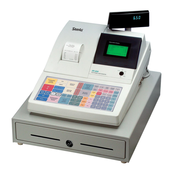
ER-650 / 650R
Manual
C O N T E N T S
1.
Precaution Statements
2.
Product Specifications
3.
Installation and Operation
4.
Assembly and Disassembly
5.
Maintenance Adjustment
6.
Exploded View and Part List
7.
PBA Layout and Part List
8.
Trouble Shooting
9.
Block diagram
10. Wiring Diagram
11. Schematic Diagram
Advertisement
Table of Contents

Related Manuals for Sam4s ER-650 Series


Summary of Contents for Sam4s ER-650 Series
- Page 1 All manuals and user guides at all-guides.com ELECTRONIC CASH REGISTER ER-650 / 650R SERVICE Manual ELECTRONIC CASH REGISTER C O N T E N T S Precaution Statements Product Specifications Installation and Operation Assembly and Disassembly Maintenance Adjustment Exploded View and Part List PBA Layout and Part List Trouble Shooting Block diagram...
- Page 2 All manuals and user guides at all-guides.com...
- Page 3 All manuals and user guides at all-guides.com Overview of this ECR This service manual provides the technical information for many individual component systems, circuits and gives an analysis of the operations performed by the circuits. If you need more technical information, please contact our service branch or R&D center.
-
Page 4: Precaution Symbols
All manuals and user guides at all-guides.com About this Manual This service manual describes how to perform hardware service maintenance for the SAM4S ER-650/R Series Electronic Cash Register. Notes Notes may appear anywhere in the manual. They describe additional information about the item. - Page 5 This manual may not, in whole or in part, be copied, photocopied, reproduced, translated or converted to any electronic or machine readable from without prior written permission of Shin Heung Precision . SAM4S ER-650/R SERIES Service Manual First edition. July 2007. V2.0 Printed in KOREA...
-
Page 6: Precaution Statements
Remplacer uniquement avec une batterie du même type recommended by the manufacturer. ou d’un type équivalent recommandé par le constructeur. Dispose used batteries according to the manufacturer’s Mettre au rebut les batteries usagées conformément aux instructions. instructions du fabricant. SAM4S ER-650 SERIES... -
Page 7: Servicing Precautions
5. Use only a grounded-tip soldering iron when soldering or unsoldering ESDs. 6. Use only an anti-static solder removal device. Many solder removal devices are not rated as anti-static; these can accumulate sufficient electrical charge to damage ESDs. SAM4S ER-650 SERIES... -
Page 8: Product Specifications
• AC 120V 60Hz, 230V 50Hz Power Requirement • Temperature : 0℃ ~ 45℃ Environment Condition • humidity : 30% ~ 80% RH • 13.7 Kg (SET), 15.8Kg (Box Packing) Weight • 400(W) × 450(D) × 282.7(H) Dimensions(mm) Table2-1 General Specifications SAM4S ER-650 SERIES... - Page 9 All manuals and user guides at all-guides.com 2 Product Specifications 2-2 Appearance 2-2 A. Appearance Dimensions (mm) 282.7 Figure2-1 Dimensions SAM4S ER-650 SERIES...
-
Page 10: Feature Locations
All manuals and user guides at all-guides.com 2 Product Specifications 2-2 B. Feature Locations Figure2-2 Feature Locations SAM4S ER-650 SERIES... -
Page 11: Printer Specification
• Reflecting Photo Sensor Sensor Paper-End Sensor • Micro Switch Cover Open Sensor • 15,000,000 Lines Life Reliability • 37,000,000 Line MCBF • 82.5 (W) ×147.3 (D) ×101.4 (H) Dimension (mm) • Approx. 365 g Weight Table2-2 Thermal Printer Specifications SAM4S ER-650 SERIES... -
Page 12: Paper Specification
• 12(W) × 24(H) Font (Including a horizontal spacing) Character Structure • 1.25 mm(W) ×3.0 mm(H) Character Size • 1.5 mm Column Pitch • 3.75 mm (Including 6-dot line spacing) Line Pitch • 32 (12×24 Font/Character) Number of Column Table2-4 Character Specification SAM4S ER-650 SERIES... -
Page 13: Other Component Specification
• 1A ~ 50 mA Current Rating • On when the printer head is load Detect Method Table2-5 Other Component Specification 2-3 F. Printer Connector 2-3 F-(a) Cover Open Sensor Pin Assignments Pin No. Signal Description Remark Table2-6 Printer Pin Assignment SAM4S ER-650 SERIES... - Page 14 Phase A Phase A_ 2-3 F-(c) Paper-End Sensor Pin Assignments Pin No. Signal Description Remark Paper End Signal 2-3 F-(d) Thermal Head Connector Pin Assignments Pin No. Signal Description Remark /LAT STB1 STB2 STB3 STB4 STB5 STB6 SAM4S ER-650 SERIES...
-
Page 15: Power Specification
: AC 230V, 80mA, 50Hz (Min : 198V, Max : 264V) • Stand-By : 10W Power Consumption • Operating : 15W • AC 19V 2.3A (Wire Color : Blue-Blue) Power Transformer Output Voltage Output • AC 24V 0.15A (Wire Color : Red-Red) Table2-7 Power Specification SAM4S ER-650 SERIES... -
Page 16: Interface Specifications
3 (TXD) 3 (RSD) 4 (RTS) HOST SIDE(9P) 5 (CTS) 8 (CTS) SIDE(25P) 6 (DSR) 6 (DSR) 4 (DTR) 20 (DTR) 7(S.G) 5 (S.G) DSR and CTS are shorted on I/F PBA of ER-5200 Figure2-5 RS232C Cable Connection SAM4S ER-650 SERIES... - Page 17 Then the host recognizes that the ECR is busy. So, the host does not transmit a data to the ECR. If the ECR is released from busy, the ECR transmits XON(ASCII 11h) to host through the Serial Data Line. Then the host recognizes that the ECR is not busy. And the host transmits a data to the ECR. 2-10 SAM4S ER-650 SERIES...
- Page 18 2-5 B-(c) Cable Connection 1 (TX/RX_B) 1 (TX/RX_B) 2 (TX/RX_B) 2 (TX/RX_B) 3 (F.GND) 3 (F.GND) MASTER or SLAVE SLAVE 4 (F.GND) 4 (F.GND) 5 (TX/RX_A) 5 (TX/RX_A) 6 (TX/RX_A) 6 (TX/RX_A) Figure2-7 IRC Cable Connection SAM4S ER-650 SERIES 2-11...
- Page 19 Transmit/Receive Data Line A Pin 4 and Pin 5 are shorted each other on I/F PBA. 6(12) TX/RX_A In/Out Table2-21 IRC Signal Description Note : The signal description of the Port#2 are same as it of the Port#1 2-12 SAM4S ER-650 SERIES...
-
Page 20: System Configuration
All manuals and user guides at all-guides.com 3 Installation and Operation 3-1 System Configuration 3-1 A. Configuration Figure3-1 System Configuration SAM4S ER-650 SERIES... -
Page 21: Paper Roll Installation
1. Connect the RS-232C serial cable to the RS-232C serial port on the right side of ECR. 2. Secure the serial cable with screws. 3. Connect the other end of the RS-232C serial Cable to your host computer. SAM4S ER-650 SERIES... - Page 22 Description Remark Paper Roll 1 EA Cable Tie 2 EA Ferrite Core RING-TR29A : 2 EA Mode Key VD, REG, X, Z, P, C User Manual 1 EA Clerk Key 5EA, 10EA, 15EA Option Table 3-2 Supplies SAM4S ER-650 SERIES...
-
Page 23: Operation
Off, Register, Manager, Clear Totals Void, Off, Register, Manager, Clear Totals, Program Void, Off, Register, Manager, Clear Totals, Program, Service Mode Table3-4 Key Function Note: The Key can be removed from the key lock in the OFF or REGISTER position. SAM4S ER-650 SERIES... -
Page 24: All Clear
= = = = = = = = = = = = = = = = = = = = = RAM ALL CLEAR OK ! = = = = = = = = = = = = = = = = = = = = = CLERK 00 No. 000001 00 Figure3-6 All Clear SAM4S ER-650 SERIES... - Page 25 3. After testing the buzzer, Some characters are displayed on the rear VFD display 4. After testing the rear VFD display, the LCD display tests. The LCD is filled with a black screen. And then the black screen erase. Figure3-9 Display Self Test SAM4S ER-650 SERIES...
- Page 26 5.Press 2 key on the key board. (2= Loop Back Test for IRC) The message (TEST IRC OK) is displayed on LCD. Note: When the ports is no connection or the cable is open, the Error occur. SAM4S ER-650 SERIES...
- Page 27 All manuals and user guides at all-guides.com 3 Installation and Operation Memo SAM4S ER-650 SERIES...
-
Page 28: Assembly And Disassembly
3. Remove the two screws (B-10). And separate the Clerk Key Ass’y (B-13) from the BRKT Mode S/W (B-8). (Page 6-3) Note: The position of Ferrite core and the number of turn refer to the display part of chapter specification. Note: To Install, Reverse the removal procedure. SAM4S ER-650 SERIES... - Page 29 1. Separate the Drawer, Compulsory harness (r, s) from the Main PBA (E-12). (Page 6-12) 2. Remove the four screws (E-10) on the Main PBA (E-12). (Page 6-12) 3. Remove the Main PBA (E-12). (Page 6-12) Note: To Install, Reverse the removal procedure. SAM4S ER-650 SERIES...
-
Page 30: Maintenance And Adjustment
Caution: Note that the thermal head becomes very hot during normal operation. To prevent the danger of Burn injury from thermal, be sure to wait for about 10 minutes after turning power off before beginning the cleaning. SAM4S ER-650 SERIES... -
Page 31: Lcd Display Contrast
You can adjust the view angle of the Operator LCD Display Figure5-2 Adjustment of the View Angle 5-2 B. LCD Display Contrast You can adjust the contrast of the Operator LCD Display by using the VR on the left side. Figure5-3 Adjustment of Contrast SAM4S ER-650 SERIES... -
Page 32: Exploded View And Part List
All manuals and user guides at all-guides.com 6 Exploded View and Part List Figure6-1 Total Disassembly (ER-650/ER-650R) SAM4S ER-650 SERIES... - Page 33 All manuals and user guides at all-guides.com 6 Exploded View and Part List Figure6-2 ASS’Y COVER-PRINTER A. ASS’Y COVER-PRINTER Parts No. Description / Specification Q`ty Design-Location Serviceable Remark JK97-10008A MEA HOU-COVER PRINTER:ER-650R,STD JK70-10320A IPR-CUTTER PAPER JK72-20011B PMO-COVER PRINTER SAM4S ER-650 SERIES...
- Page 34 All manuals and user guides at all-guides.com 6 Exploded View and Part List Figure6-3 ASS’Y CASE-UPPER SAM4S ER-650 SERIES...
- Page 35 PMO-WINDOW TURRET:PC,BL06,HB B-17 JK92-00970A PBA SUB-650,TURRET:BASIC B-18 JK68-00013A LABEL(P)-TURRET SHEET: PE,L100*W70 B-19 JK72-00016A PMO-TURRET BODY: HIPS(V0) B-20 JK72-00047A PMO-WINDOW LOWER: HIPS(V0) B-21 JK72-00038A PMO-CASE UPPER: HIPS(V0) B-22 6001-000367 SCREW-MACHINE:FH,+,M4,L10,NI C/U+C/L(RIGHT) B-23 JK72-00048A PMO-WINDOW HOLDER: POM,WHITE,HB B-24 6002-000174 SCREW-TAPPING:PWH,+,2,M3,L10,ZPC SAM4S ER-650 SERIES...
- Page 36 All manuals and user guides at all-guides.com 6 Exploded View and Part List Figure6-4 ASS’Y PRINTER(STM-210) SAM4S ER-650 SERIES...
- Page 37 All manuals and user guides at all-guides.com 6 Exploded View and Part List Figure6-5 Lubrication Points of the Printer (STM-210) SAM4S ER-650 SERIES...
- Page 38 JK47-10001A TPH: ROHM C-33 JK70-50005A TPH TAPE: 3M JK70-20006A HEAT-SINK: ZNDC C-34 JK70-30002A SPRING-TPH: SWP C-35 JK70-20005A IPR-BRACKET-REAR: SECC T1.0 C-36 6001-000665 SCREW-MACHINE: PWH,+,2,M3,L4,ZPC C-37 JK72-20002A PMO-PAPER SUPPLY: ABS+GF 20% C-38 JK92-01224A PBA-SUB PRT CONN BOARD: STM-210 SAM4S ER-650 SERIES...
- Page 39 ELA PARTITION ASS'Y: STM-220 STM-220 JK72-20114A PMO-PAPER SEPARATOR: ABS,BLACK C-49 JK72-20114A PMO-PAPER SEPARATOR: ABS,BLACK STM-220 C-50 JK72-20023A PMO-HOSUING-PAPER END C-51 JK72-20023A PMO-KNOB-PAPER END OPTION C-52 6002-000175 SCREW-TAPPING: PWH,+,2,M3,L8,ZPC C-53 JK96-01232A ELA NEAR PAPER END SENSOR PCB C-54 6002-001079 SCREW-TAPPING: PWH,+,2,M3,L5,ZPC SAM4S ER-650 SERIES...
- Page 40 PRINTER. 3. Disassemble the TPH assembly by pulling the 4. Assemble the TPH assembly in reverse order and lower part of TPH assembly and lift it up. close the COVER TOP. Figure6-6 Thermal Printer Head assembly replacement SAM4S ER-650 SERIES...
- Page 41 All manuals and user guides at all-guides.com 6 Exploded View and Part List Figure6-7 ASS’Y KEYBOARD (FLAT) Figure6-8 ASS’Y KEYBOARD (RAISED) 6-10 SAM4S ER-650 SERIES...
- Page 42 KEY-TOP,3 JK81-10936A KEY-TOP,4 JK81-10937A KEY-TOP,5 JK81-10938A KEY-TOP,6 JK81-10939A KEY-TOP,7 JK81-10940A KEY-TOP,8 JK81-10941A KEY-TOP,9 JK81-10942A KEY-TOP,0 JK81-10943A KEY-TOP,00 JK81-10944A KEY-TOP,● D-10 JK81-20002A KBD-HOUSING D-11 JK81-20003A AS-FPC ASSY:ER-650R D-12 JK81-20004A FRAME D-13 JK81-20005A SCREW-TAPTITE D-14 JK73-20211A WATER- PROOF:ER-650R,URETANE SAM4S ER-650 SERIES 6-11...
- Page 43 All manuals and user guides at all-guides.com 6 Exploded View and Part List Figure9-6 ASS’Y CASE-LOWER 6-12 SAM4S ER-650 SERIES...
- Page 44 JK39-00008A CBF- POWER S/W: UL1617,UL/CSA,150 JK39-10002A CBF-POWER CORD: AUSTRALIA JK39-10003A CBF-POWER CORD: USA E-18 JK39-10008A CBF-POWER CORD: UK JK39-10501A CBF-POWER CORD: EUROPE E-19 JK39-40200A CBF HARNESS: UL1007,250MM E-20 JK39-40302C CBF HARNESS: UL1007,180MM E-21 JK92-00948D PBA I/F-BOARD SAM4S ER-650 SERIES 6-13...
- Page 45 ASS'Y HOUSING d. ASS'Y LOCK b. ASS'Y TRAY-TILL e. ASS'Y BOTTOM Figure6-11 ASS’Y DRAWER (5B/5C) a. ASS'Y BILL-COIN (7B8C) c. ASS'Y HOUSING d. ASS'Y LOCK b. ASS'Y TRAY-TILL e. ASS'Y BOTTOM Figure6-12 ASS’Y DRAWER (7B/8C) 6-14 SAM4S ER-650 SERIES...
- Page 46 JK73-10203A RPR-TENSION: DRAWER,SPONGE,BLK JK75-10386A MEC-ROLLER: DRAWER,DR-10-B1/ Φ19 6031-000549 WASHER-PLAIN: IDΦ6.5,ODΦ13, T1.0 6003-000221 SCREW-TAPTITE: PWH,+2,M4,L8,ZPC(YEL) JK70-10324A IPR-SUPPORT TRAY: DRAWER,SBHG-1,T1.2 JK70-40302A ICT,SHAFT PIN: A-TYPE b-10 6044-000124 RING-E: IDΦ3,ODΦ7, T0.6,ZPC(BLK),STSC b-11 6002-001042 SCREW-TAPPING: FH,+2,M3,L6 b-12 JK70-10323A IPR-PLATE CLIP: DRAWER,SWP,T0.5 SAM4S ER-650 SERIES 6-15...
- Page 47 MEA-UNIT BOTTOM: A-TYPE JK97-01076B MEA-UNIT BOTTOM: A-TYPE,UNIVERSAL JK70-10938A IPR-PLATE BOTTOM: A-TYPE,SBHG-1,T1.0 JK73-40200A RMO-STOPPER: DRAWER,NR,BLK JK73-10902A RMO-STOPPER: DRAWER,NR,BLK,UNIVERSAL JK61-40200A RMO-FOOT RUBBER: DRAWER,NR,GRAY,80HB 6002-000234 SCREW-TAPPING: TH,+2,M4,L16,ZPC(YEL) 6003-000267 SCREW-TAPTITE: PWH,+2,M3,L8,ZPC(YEL) 6003-000267 SCREW-TAPTITE: PWH,+2,M3,L8,ZPC(YEL) JK70-10401A IPR-PLATE SPRING: DRAWER,STS304,T0.3 6003-000267 SCREW-TAPTITE: PWH,+2,M3,L8,ZPC(YEL) 6-16 SAM4S ER-650 SERIES...
- Page 48 All manuals and user guides at all-guides.com 7 PBA Layout and Part List 7-1 Main PBA SAM4S ER-650 SERIES...
- Page 49 3711-000033 CONNECTOR-HEADER:BOX,2P,1R,2.5mm,STRAIG CN15 3711-000041 CONNECTOR-HEADER:BOX,8P,1R,2.5mm,STRAIG 3711-000183 CONNECTOR-HEADER:1WALL,2P,1R,3.96mm,STR CN3,CN4 3711-000242 CONNECTOR-HEADER:1WALL,4P,1R,3.96mm,STR 3711-000840 CONNECTOR-HEADER:BOX,30P,2R,2MM,STRAIGH CN22 3711-001054 CONNECTOR-HEADER:BOX,6P,1R,2.5mm,STRAIG 3711-001133 CONNECTOR-HEADER:BOX,8P,1R,2.5mm,STRAIG CN16,CN18 3711-003359 CONNECTOR-HEADER:BOX,10P,1R,2.5mm,STRAIG CN6,CN17 3711-003969 CONNECTOR-HEADER:BOX,2P,1R,2.5mm,STRAIG CN2,CN5 3711-001011 CONNECTOR-HEADER:BOX,5P,1R,2.5mm,STRAIG 4302-000126 BATTERY-NICD(2ND):3.6V(1.2Vx3),60mAH,CYL BAT1 JK27-60100B COIL FILTER:SER-6500,220 UH,-,- JK27-60100D COIL FILTER:ER-350,140 UH,-,- SAM4S ER-650 SERIES...
- Page 50 2007-000653 R-CHIP:27KOHM,5%,1/10W,DA,TP,2012 2007-000457 R-CHIP:18KOHM,5%,1/10W,DA,TP,2012 R20,R110,R1,R82,R119,R2 2007-000468 R-CHIP:1KOHM,5%,1/10W,DA,TP,2012 R72,R77,R97,R86 2007-000493 R-CHIP:2.2KOHM,5%,1/10W,DA,TP,2012 R88,R92,R76,R37,R84,R81 2007-000686 R-CHIP:3.3KOHM,5%,1/10W,DA,TP,2012 R80,R90 R12,R42,R52,R60,R63,R103 R45,R62,R64,R55,R58,R33 R51,R50,R59,R57,R73,R32 R39,R78,R83,R46,R48,R71 2007-000872 R-CHIP:4.7KOHM,5%,1/10W,DA,TP,2012 R113,R54,R125,R74,R26 R47,R85,R56,R9,R14,R44 R38,R114,R61,R53,R49 R200,R201 2007-000941 R-CHIP:47KOHM,5%,1/10W,DA,TP,2012 2007-001071 R-CHIP:6.8KOHM,5%,1/10W,DA,TP,2012 2007-001113 R-CHIP:680KOHM,5%,1/10W,DA,TP,2012 R123 2007-001118 R-CHIP:680OHM,5%,1/10W,DA,TP,2012 R124 2007-001662 R-CHIP:36KOHM,1%,1/10W,DA,TP,2012 R17,R23 SAM4S ER-650 SERIES...
- Page 51 C-CERAMIC,CHIP:0.03nF,5%,50V,NP0,TP,2012 C52,C54,C59,C42,C43 C9,C56 C22,C23,C121,C34,C25,C14 2203-000938 C-CERAMIC,CHIP:0.47nF,5%,50V,NP0,TP,2012 C20,C48,C19 2402-000168 C-AL,SMD:100uF,20%,16V,GP,TP,8.3x8.3x6.3 C44,C90,C116 2402-000179 C-AL,SMD:47uF,20%,16V,GP,TP,6.6x6.6x5.4 C60,C75 2402-000139 C-AL,SMD:22uF,20%,35V,GP,TP,6.6x6.6x5.4 C38,C99 2402-000117 C-AL,SMD:10uF,20%,35V,GP,TP,5.3x5.3x5.4 L53,L44,L51,L56,L57,L37 L50,L41,L42,L47,L39,L4,L14 3301-000325 CORE-FERRITE BEAD:AB,3.2x2.5x1.3mm,-,- L40,L46,L17,L54,L45,L55 L52,L6,L5,L21,L48,L43,L38 L7,L49 L8,L29,L19,L18,L26,L24,L1 L22,L16,L12,L13,L31,L23 3301-000317 CORE-FERRITE BEAD:AB,2x1.25x0.9mm,-,- L30,L25,L28,L27,L11,L9,L3 L15,L20 JK41-00011C PCB-MAIN:ER-650/R,FR-4,2L,T1.6mm,RoHS Serial RTC SAM4S ER-650 SERIES...
- Page 52 Code No. Description / Specification Q’TY Design-Location Serviceable Remarks JK92-00949A PBA PWR-650;ER-650,BASIC,WORLD 1405-000111 VARISTOR;1800V,4500A,17.5x15mm 1405-000147 VARISTOR;470V,4500A,17x12mm,BK V1,2 2201-000023 C-CERAMIC,DISC;2.2nF,20%,125V, C4,5 2305-001021 C-FILM,MPEF;100nF,20%,275V,TP, 3601-000246 FUSE-FERRULE;250V,2A,TL,GLASS, 3602-000001 FUSE-CLIP;-,-,30mohm 3711-000829 CONNECTOR-HEADER;BOX,2P,1R,6.2 3711-000829 CONNECTOR-HEADER;BOX,2P,1R,6.2 3711-002104 CONNECTOR-HEADER;1WALL,2P,1R,7 JC27-60503A COIL FILTER-3mH;ML5500,3.0mH,0 PCB-650 POWER;ER-650,FR-1,1L,T JK41-00013A SAM4S ER-650 SERIES...
- Page 53 U2,U3 2203-000192 C-CERAMIC,CHIP:100nF,+80-20%,50V,Y5V,TP, C4,C6 C7,C10,C11,C12,C16,C1, 2203-000938 C-CERAMIC,CHIP:0.47nF,5%,50V,NP0,TP,2012 C20,C24 C8,C9,C13,C14,C15,C17, 2402-000170 C-AL,SMD:1uF,20%,50V,GP,TP,4.3x4.3x5.4, C18,C21,C22,C23 2203-000495 C-CERAMIC,CHIP:2.2nF,10%,50V,X7R,TP,2012 C2,C3 2203-000784 C-CERAMIC,CHIP:0.33nF,5%,50V,NP0,TP,2012 C1,C5 L2,L3,L5,L6,L7,L8,L9,L10, 3301-000317 CORE-FERRITE BEAD:AB,2x1.25x0.9mm,-,- L11,L12,L13,L14,L15,L16, L17,L18,L19,L20,L21,L22 0501-000279 TR-SMALL SIGNAL:KSA1182-Y,PNP,150mW,SOT- 2007-000931 R-CHIP:470OHM,5%,1/8W,DA,TP,2012 2007-000872 R-CHIP:4.7KOHM,5%,1/10W,DA,TP,2012 R2,R4,R5 2007-001013 R-CHIP:51OHM,5%,1/10W,DA,TP,2012 L1,L4 JK41-10546A PCB-I/O:ER-650/5200,FR-4,2L,T1.6,97*46mm SAM4S ER-650 SERIES...
-
Page 54: Display Layout
Serviceable Remarks JK92-00970A PBA SUB-650,TURRET:ER-650,BASIC ER-650 0402-000129 DIODE-RECTIFIER;1N4003,200V,1A 0402-000208 DIODE-RECTIFIER:EK-04,40V,1.5A,DO-41 2202-000579 C-CERAMIC,MLC-AXIAL:100nF,+80-20%,50V,Z5 C1,C2 1003-001381 IC-VFD:HV5812P,DIP,28P,540MIL,-,-,ST,PLA 3711-001133 CONNECTOR-HEADER;BOX,8P,1R,2,5 JC39-40511A CBF-HARNESS;ML-80,JUMPER,AWG22 J1 ~ J9 JK07-00005A DISPLAY VFD-DC10G:FUTABA,10-LT-50GK JK39-00042A CBF HARNESS-TURRET(WITH TUBE); TURRET TO MAIN JK41-10547A PCB-TURRET:ER-650/5200,FR-1,1L,T1.6 JK73-10207A RPR-PAD;ER-220N,SPONGE,-,BLK,- T5.0 SAM4S ER-650 SERIES... - Page 55 Description / Specification Q’TY Design Location JK92-00132C PBA SUB-FISCAL B/D;2MBITs 2MBITs ASSY 1102-000136 IC-EPROM:27C020,256Kx8BIT,DIP,32P,600MI 0403-000141 DIODE-ZENER:1N4735A,6.2V,5%,1W,DO-41,TP JK39-40305B CBF HARNESS:,-,UL 1007,120,WHT/BLU/RED,2 2007-000029 R-CHIP:0OHM,5%,1/10W,DA,TP,2012 2007-000030 R-CHIP:560OHM,5%,1/10W,DA,TP,2012 2007-000221 R-CHIP:1.2KOHM,5%,1/10W,DA,TP,2012 2007-000872 R-CHIP:4.7KOHM,5%,1/10W,DA,TP,2012 R1,R5~R13 2203-000192 C-CERAMIC,CHIP:100nF,+80-20%,50V,Y5V,TP, 0404-001051 DIODE-SCHOTTKY:SK14,40V,1000MA,DO-214AA, D1,D2 0501-000457 TR-SMALL SIGNAL:MMBT2222A,NPN,350MW,SOT- JK41-10531B PCB-FISCAL:ER-5240F,FR-4,2L,T1.6mm,348X5 SAM4S ER-650 SERIES...
- Page 56 All manuals and user guides at all-guides.com 7 PBA Layout and Part List MEMO SAM4S ER-650 SERIES...
-
Page 57: Troubleshooting
1. Check the IC34063 (U1) 2. Check the TR 1010 (Q11) 2. Check the TR1010,708 (Q2,3) 3. Check Generated Frequency 3. Check Generated Frequency Power VH (+8V) Ok? 1. CPU the Port 1.7 (VH_on_off) 2. Check the TR1010,708 (Q6,7) SAM4S ER-650 SERIES... -
Page 58: System Problem
2. Check & Change the EP-ROM SRAM 1. Check the /CS Decoder HC138 (U2) 2. Check the Each SRAM 3. Check the Addr/Data Pattern 1. Check the Main Clock(14.7456MHz) 2. Check the Addr/Data Pattern 3. Replace the Main PBA. SAM4S ER-650 SERIES... - Page 59 1. Check the CPU INTP1 (P8.3) 2. Check the TR A473, 2222 (14,16) 3. Check the LF33CV (U27) Contrast 1. Check the VR1(10K) 2. Check the LCD Output VO 3. Check the Harness 4. Check & Replace the LCD Module SAM4S ER-650 SERIES...
- Page 60 VCC Ok? 1. Refer to the Power Problem. 2. Check the Harness. VFD PBA Assy Ok? 1. Check and Replace the VFD PBA. 2. Check the UCL5812. 3. Check the VFD. 4. Check THE Harness & Soldering Point. SAM4S ER-650 SERIES...
- Page 61 2. Check the Harness. 3. Check the Sensor PBA. Feed Motor 1. Check the related Circuit and Pattern(IC LB1838). 2. Check the Harness. 3. Check the Feed Step Motor . Printer Work 1. Replace the Thermal Printer . SAM4S ER-650 SERIES...
-
Page 62: Key Board Problem
2. Check the Matrix Bus & Data Bus 3. Check the Diodes(D13~D28) 4. Check the Key Board Ass’y Mode Key 1. Check the Harness & Mode Key Ass’y 2. Check Diode (D23) 3. Check the HCT541 & Data Bus SAM4S ER-650 SERIES... - Page 63 1. Check the Compulsory Harness & Connector. 2. Check the micro switch in the Drawer. RTC Problem 1. Check the Clock (32.768KHz) 2. Check the Battery Voltage (VBU) 3. Check the RF5c15 & the related circuit. (Addr/Data bus, /CS signal) SAM4S ER-650 SERIES...
-
Page 64: Rs-232C Serial Communication Problem
3. Check whether Signal is affected by the Cable Noise. H/W Handshake 1. Check the connection of the H/W handshaking Line and Other side 2. Check the I/F Cable whether it is open or short. 3. Confirm the H/W handshaking Protocol. SAM4S ER-650 SERIES... - Page 65 3. Check the 75176 Driving Chip and related Circuit on I/F PBA. Communication Failure? 1. Check the connection of the IRC Connector and Other side. 2. Check the IRC Cable whether it is open or short. 3. Check whether Signal is affected by the Cable Noise. SAM4S ER-650 SERIES...
- Page 66 All manuals and user guides at all-guides.com 8 Trouble Shooting Memo 8-10 SAM4S ER-650 SERIES...
-
Page 67: Block Diagram
DRIVER DATA ADDRESS Expansion MODE KEY MODE KEY SRAM DRIVER (4 Mbit×2) DATA ADDRESS Real Time CLERK KEY CLERK KEY Clock DRIVER (32.768KHz) DATA THERMAL PRT THERMAL PRT BUZZER BUZZER DRIVER STM-210 CIRCUIT CLOCK CIRCUIT (14.7456MHz) Option SAM4S ER-650 SERIES... - Page 68 All manuals and user guides at all-guides.com 9 Block Diagram Memo SAM4S ER-650 SERIES...
-
Page 69: Wiring Diagram
Back Light Voltage CN15 Step Motor B- Step Motor B Disconnect Check Step Motor A Pull-Up Step Motor A- LATCH 8.5V Vdi(+30V) DATA MODE KEY Drawer signal CLERK KEY DRAWER Compulsory CN19 CN20 CN13 FISCAL MEMORY KEY BOARD SAM4S ER-650 SERIES 10-1... - Page 70 All manuals and user guides at all-guides.com 10 Wiring Diagram Memo 10-2 SAM4S ER-650 SERIES...
- Page 71 7) Key Scan Block ---------------------------------------------------- 11-8 8) LCD Display Block ------------------------------------------------ 11-9 9) Printer Block-------------------------------------------------------- 11-10 10) Printer Connection Block--------------------------------------- 11-11 2. Interface PCB Schematics. -------------------------------------- 11-12 3. Rear Display PCB Schematics----------------------------------- 11-13 4. Fiscal PCB Schematics-------------------------------------------- 11-14 SAM4S ER-650 SERIES 11-1...
- Page 72 All manuals and user guides at all-guides.com 11-1 CPU PART M30622SFP 100nF 100nF 100nF C103 100nF 100nF 100nF 100nF 100nF 100nF 100nF C117 100nF 100nF 100nF 100nF 100nF 100nF 11-2 SAM4S ER-650 SERIES...
-
Page 73: Memory Part
All manuals and user guides at all-guides.com 11-2 MEMORY PART SAM4S ER-650 SERIES 11-3... - Page 74 All manuals and user guides at all-guides.com 11-3 BUZZER / POWER FAIL / RTC PART 4.7K 4.7K 4.7K 4.7K 4.7K 4.7K 4.7K 4.7K 74HCT541 470pF 470pF 470pF 470pF 470pF 100nF 11-4 SAM4S ER-650 SERIES...
- Page 75 All manuals and user guides at all-guides.com 11-4 FISCAL PART SAM4S ER-650 SERIES 11-5...
-
Page 76: Power Part
All manuals and user guides at all-guides.com 11-5 POWER PART 11-6 SAM4S ER-650 SERIES... - Page 77 All manuals and user guides at all-guides.com 11-6 DRAWER / DISPLAY(VFD) PART SAM4S ER-650 SERIES 11-7...
- Page 78 All manuals and user guides at all-guides.com 11-7 KEY SCAN PART 11-8 SAM4S ER-650 SERIES...
-
Page 79: Lcd Display Part
All manuals and user guides at all-guides.com 11-8 LCD DISPLAY PART SAM4S ER-650 SERIES 11-9... -
Page 80: Printer Part
All manuals and user guides at all-guides.com 11-9 PRINTER PART 11-10 SAM4S ER-650 SERIES... - Page 81 All manuals and user guides at all-guides.com 11-10 PRINTER CONNECTION PART SAM4S ER-650 SERIES 11-11...
-
Page 82: Interface Pcb
All manuals and user guides at all-guides.com 11-11 Interface PCB 11-12 SAM4S ER-650 SERIES... - Page 83 All manuals and user guides at all-guides.com 11-12 Display (Rear) SAM4S ER-650 SERIES 11-13...
- Page 84 All manuals and user guides at all-guides.com 11-13 Fiscal PCB 11-14 SAM4S ER-650 SERIES...
-
Page 85: Update Log
Use this page to record any special servicing information such as Service Bulletins or Supplements. When possible, record changes to Code numbers directly on the actual Parts List. Always records Service Bulletin numbers and Application Dates on this log to ensure that your data is always as current as possible. SAM4S ER-650 SERIES... - Page 86 All manuals and user guides at all-guides.com...
- Page 87 All manuals and user guides at all-guides.com ⓒ Shin Heung Precision. July 2007 Printed in KOREA V2.0 Code No. : JK68-00061B...