Table of Contents
Advertisement
Quick Links
Advertisement
Table of Contents

Related Manuals for Clevo N150SC


Summary of Contents for Clevo N150SC
-
Page 2: Instructions For Care And Operation
Preface Instructions for Care and Operation The notebook computer is quite rugged, but it can be damaged. To prevent this, follow these suggestions: Don’t drop it, or expose it to shock. If the computer falls, the case and the components could be damaged. Do not expose the computer Do not place it on an unstable Do not place anything heavy... -
Page 3: Power Safety
Preface Avoid interference. Keep the computer away from high capacity transformers, electric motors, and other strong mag- netic fields. These can hinder proper performance and damage your data. Take care when using peripheral devices. Use only approved brands of Unplug the power cord before peripherals. - Page 4 Preface Battery Precautions • Only use batteries designed for this computer. The wrong battery type may explode, leak or damage the computer. • Do not continue to use a battery that has been dropped, or that appears damaged (e.g. bent or twisted) in any way. Even if the computer continues to work with a damaged battery in place, it may cause circuit damage, which may possibly result in fire.
-
Page 5: Related Documents
Preface Related Documents You may also need to consult the following manual for additional information: User’s Manual on CD/DVD This describes the notebook PC’s features and the procedures for operating the computer and its ROM-based setup pro- gram. It also describes the installation and operation of the utility programs provided with the notebook PC. System Startup 1. -
Page 6: Specifications
Introduction Specifications Processor Options Storage Design I: (Factory Option) One 9.5mm(h) Optical Device Type Drive (Super Multi Drive) Intel® Core™ i7 Processor (Factory Option) 2.5" 9.5mm 2nd HDD/SSD caddy i7-4720HQ (2.60GHz) One Changeable 2.5" 9.5mm/7.0mm (h) SATA HDD/SSD 6MB L3 Cache, 22nm, DDR3L-1600MHz, TDP 47W Latest Specification Information Intel®... - Page 7 Introduction NVIDIA® Discrete GPU M.2 Slots Power NVIDIA® GeForce GTX 960M Slot 1 for M.2 2230 WLAN Combo Module Card with PCIe & Full Range AC/DC Adapter 2GB GDDR5 Video RAM on board USB Interfaces AC Input: 100 - 240V, 50 - 60Hz Microsoft DirectX®...
-
Page 8: External Locator - Top View With Lcd Panel Open
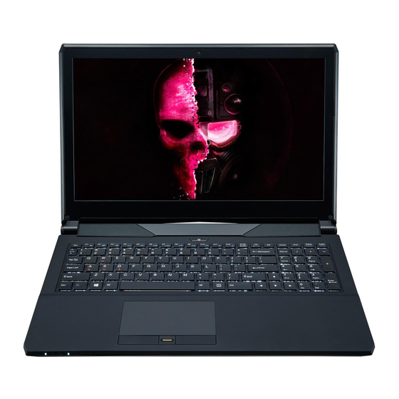
Introduction External Locator - Top View with LCD Panel Open Figure 1 Top View 1. PC Camera 2. *PC Camera LED *When the PC camera is in use, the LED will be illuminated. 3. Microphone 4. LCD 5. Speakers 6. Power Button 7. -
Page 9: External Locator - Front & Right Side Views
Introduction External Locator - Front & Right Side Views Figure 2 Front View 1. LED Indicators FRONT VIEW Figure 3 Right Side View 1. USIM Card RIGHT SIDE VIEW Reader (for 3G/ 4G USIM Cards) 2. Multi-in-1 Card Reader 3. USB 3.0 Port 4. -
Page 10: External Locator - Left Side & Rear View
Introduction External Locator - Left Side & Rear View Figure 4 Left Side View 1. Security Lock Slot 2. USB 3.0 Ports 3. S/PDIF-Out Jack LEFT SIDE VIEW 4. Microphone-In Jack 5. Headphone-Out Jack 6. Optical Device Drive Bay 7. Emergency Eject Hole Figure 5 REAR VIEW... -
Page 11: External Locator - Bottom View
Introduction External Locator - Bottom View Figure 6 Bottom View 1. Vent 2. Battery Overheating To prevent your com- puter from overhea- ting, make sure no- thing blocks any vent while the computer is in use. External Locator - Bottom View 1 - 7... -
Page 12: Chapter 2: Disassembly
Chapter 2: Disassembly Overview This chapter provides step-by-step instructions for disassembling the N150SC / N150SD series notebook’s parts and sub- systems. When it comes to reassembly, reverse the procedures (unless otherwise indicated). We suggest you completely review any procedure before you take the computer apart. -
Page 13: Removing The Battery
Disassembly Removing the Battery Figure 1 Battery Removal 1. Turn the computer off, and turn it over. 2. Locate the battery and remove screws (Figure 1a). a. Remove the screws. 3. Carefully lift the battery up in the direction of the arrow (Figure 1b b. -
Page 14: Removing The Hard Disk Drive
Disassembly Removing the Hard Disk Drive Figure 2 The hard disk drive can be taken out to accommodate other 2.5" serial (SATA) hard disk drives with a height of 9.5mm HDD Assembly or 7mm (h). Follow your operating system’s installation instructions, and install all necessary drivers and utilities (as Removal outlined in Chapter 4 of the User’s Manual) when setting up a new hard disk. - Page 15 Disassembly 5. Remove screws from the HDD assembly (Figure 3c). Figure 3 6. Lift the hard disk at a 45 degrees angle and slide it out in the direction of arrow (Figure 4d HDD Assembly 7. Remove the hard disk assembly out of the bay (Figure 4e Removal (cont’d.)
- Page 16 Disassembly 8. Remove screws from the hard disk assembly (Figure 4f Figure 4 9. Separate the hard disk from the bracket and mylar cover (Figure 4g HDD Assembly 10. Reverse the process to install a new hard disk (do not forget to insert the mylar cover between the bracket and Removal (cont’d.) hard disk as shown before replacing the screws).
- Page 17 Disassembly Hard Disk Size Note (Foam Rubber Insert) Note that the hard disks pictured on the following pages are all 9.5mm(H) hard disk drives. In some cases 7mm(H) hard disk drives will be installed. Also pay attention on the alignment of the hard disk and bracket when tightening the screws. For more information contact your distributor/supplier, and bear in mind your warranty terms.
-
Page 18: Removing The Optical (Cd/Dvd) Device
Disassembly Removing the Optical (CD/DVD) Device Figure 6 Optical Device 1. Turn off the computer, remove the battery (page 2 - 5), and bottom case (page 2 - Removal 2. Carefully push out the optical device out of the bay in the direction of the arrow (Figure 6a 3. -
Page 19: Removing The Keyboard
Disassembly Removing the Keyboard Figure 7 Keyboard Removal 1. Turn off the computer, remove the battery (page 2 - 5), and bottom case (page 2 - 2. Open it up with the LCD on a flat surface before pressing at point &... -
Page 20: Removing The System Memory (Ram)
Disassembly Removing the System Memory (RAM) Figure 8 RAM Module The computer has two memory sockets for 204 pin Small Outline Dual In-line Memory Modules (SO-DIMM) supporting Removal DDR3L up to 1600 MHz. The main memory can be expanded up to 32GB. The total memory size is automatically de- tected by the POST routine once you turn on your computer. -
Page 21: Removing The M.2 Ssd Module
Disassembly Removing the M.2 SSD Module Figure 9 M.2 SSD Module 1. Turn off the computer, remove the battery (page 2 - 5), and bottom case (page 2 - Removal 2. The M.2 SSD module will be visible at point on the mainboard (Figure 9a). -
Page 22: Removing The Wireless Lan Module
Disassembly Removing the Wireless LAN Module Figure 10 Wireless LAN 1. Turn off the computer, remove the battery (page 2 - 5), keyboard (page 2 - 11) and bottom case (page 2 - Module Removal 2. The Wireless LAN module will be visible at point on the mainboard (Figure 10a). -
Page 23: Wireless Lan, Combo, 3G & Lte Module Cables
Disassembly Wireless LAN, Combo, 3G & LTE Module Cables Note that the cables for connecting to the antennae on WLAN, WLAN & Bluetooth Combo, 3G and LTE modules are not labelled. The cables/covers (each cable will have either a black or transparent cable cover) are color coded for iden- tification as outlined in the table below. -
Page 24: Removing The 3G Module
Disassembly Removing the 3G Module Figure 11 3G Module Removal 3G Module Removal Procedure 1. Turn off the computer, remove the battery (page 2 - 5), and bottom case (page 2 - a. Locate the module. 2. Locate the module, it is visible at point Figure 11a b.