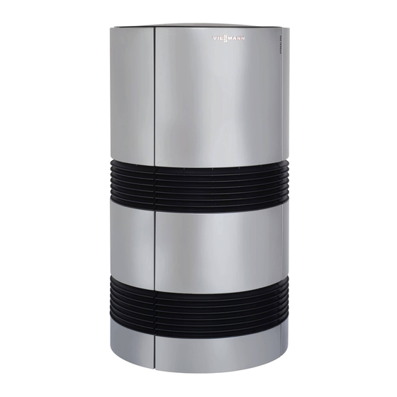
Viessmann Vitocal 300-A Connection And Wiring Diagram
Air/water heat pump with electric drive, 400 v
Hide thumbs
Also See for Vitocal 300-A:
- Installation and service instructions manual (212 pages) ,
- Installation and service instructions for contractors (124 pages) ,
- Operating instructions manual (60 pages)
Summary of Contents for Viessmann Vitocal 300-A
- Page 1 VIESMANN Connection and wiring diagram for contractors Vitocal 300-A Type AWO-AC 301.B11 to B14 Air/water heat pump with electric drive, 400 V~ VITOCAL 300-A Please keep safe. 5516 440 GB 5/2014...
-
Page 2: Safety Instructions
Safety instructions Safety instructions Please follow these safety instructions closely to prevent accidents and material losses. Safety instructions explained Flue systems and combustion air Danger Ensure that flue systems are clear and cannot be sealed, This symbol warns against the risk of injury. for instance due to accumulation of condensate or other cau- ses. - Page 3 Repair work Please note Repairing components that fulfil a safety function can compromise the safe operation of your system. Replace faulty components with genuine Viessmann spare parts. Auxiliary components, spare and wearing parts Please note Spare and wearing parts that have not been tested together with the system can compromise its function.
-
Page 4: Electrical Equipment
Connection and wiring diagram Notes ■ Observe the information on electrical connections in the Example: /7.5 installation and service instructions. = Cross-reference ■ In the case of a power supply with power-OFF facility, the 7. = Sheet number power to the control circuit (heat pump control unit) must be 5 = Current path supplied without interruption by the power supply utility. - Page 5 Connection and wiring diagram Sheet 1, compressor power circuit A Earth rivet F Inverter B Mains terminal G Inverter mains input C Fan H Modbus refrigerant circuit controller D Fan terminal K Compressor E Coils L Mains...
- Page 6 Connection and wiring diagram Sheet 2, safety chain A Mains K Thermal relay - fan B Power supply, cross connect PCB L Fan terminal C Demand externally M Frost stat D Jumper (fault message, lag heat pump) N Safety high pressure switch E Message, flow switch P Control high pressure switch F Block externally...
- Page 7 Connection and wiring diagram Sheet 3, main PCB A Safety chain B Ribbon cable to the controller and sensor PCB...
- Page 8 Connection and wiring diagram Sheet 4, expansion PCB A Ribbon cable to the controller and sensor PCB...
- Page 9 Connection and wiring diagram Sheet 5, controller and sensor PCB A EEV PCB F Temperature sensor, air discharge (Pt500A) B Ribbon cable to the main PCB and expansion PCB G Return temperature sensor, secondary circuit (Pt500A) C To the programming unit H Heat pump interface D Coding card K Flow temperature sensor, secondary circuit (Pt500A)
- Page 10 Connection and wiring diagram Sheet 6, cross connect PCB A Heat pump interface...
- Page 11 Connection and wiring diagram Sheet 7, EEV PCB A 4-way diverter valve K High pressure sensor B Solenoid valve, intermediate injection L Suction gas temperature sensor (upstream of compres- C Modbus: Inverter switching sor) (NTC 10 kΩ) M Liquid gas temperature sensor (downstream of con- D Modbus: Fan switching denser) (NTC 10 kΩ) E Modbus: Connection cable to the controller and sensor...
- Page 12 Viessmann Werke GmbH&Co KG Viessmann Limited D-35107 Allendorf Hortonwood 30, Telford Telephone: +49 6452 70-0 Shropshire, TF1 7YP, GB Fax: +49 6452 70-2780 Telephone: +44 1952 675000 www.viessmann.com Fax: +44 1952 675040 E-mail: info-uk@viessmann.com Viessmann Werke GmbH&Co KG Viessmann Limited...


