Table of Contents
Advertisement
Quick Links
57413
8/16/03
11:50 PM
P/N 57413
Page i
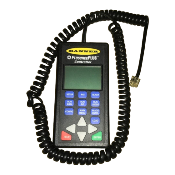
Instruction Manual
Model PRC1
Controller
WARNING . . . Not To Be Used for Personnel Protection
Never use these products as sensing devices for personnel protection. Doing
so could lead to serious injury or death.
These sensors do NOT include the self-checking redundant circuitry necessary to allow
their use in personnel safety applications. A sensor failure or malfunction can cause
either an energized or de-energized sensor output condition. Consult your current
Banner Safety Products catalog for safety products which meet OSHA, ANSI and IEC
standards for personnel protection.
08/03
Advertisement
Table of Contents

Related Manuals for Banner PresencePLUS PRC1


Summary of Contents for Banner PresencePLUS PRC1
- Page 1 A sensor failure or malfunction can cause either an energized or de-energized sensor output condition. Consult your current Banner Safety Products catalog for safety products which meet OSHA, ANSI and IEC standards for personnel protection.
- Page 2 57413 8/16/03 11:50 PM Page ii...
-
Page 3: Table Of Contents
Glossary ..........35 Banner Engineering Corp. • Minneapolis, MN U.S.A. - Page 4 57413 8/16/03 11:50 PM Page 2 P/N 57413...
-
Page 5: Overview
PRC1 SETUP TEACH To P ower Source, Trigger Device, and MAIN JUDGE MAIN IMAGE Output Receivers CONFIG MENU CNTRL LOAD HELP ENTER Controller Connection to the Sensor Banner Engineering Corp. • Minneapolis, MN U.S.A. www.bannerengineering.com • Tel: 763.544.3164 P/N 57413... -
Page 6: Product Overview
57413 8/16/03 11:50 PM Page 4 OVERVIEW Product Overview The PresencePLUS™ Model PRC1 Controller is a hand-held remote In the third step, the TEACH mode is used to “teach” the sensor to programmer for the PresencePLUS™ Model P1B65Q Pixel-Counting recognize good and (optionally) bad images by presenting a number of Sensor. -
Page 7: Controller Keypad
CONFIGURE CONFIG – Light auto-compensation – Tr igger settings Display information about – Output settings the selected option • U pload or Download configuration files LOAD Banner Engineering Corp. • Minneapolis, MN U.S.A. www.bannerengineering.com • Tel: 763.544.3164 P/N 57413... -
Page 8: Working With Screens
57413 8/16/03 11:50 PM Page 6 OVERVIEW Working with Screens • The screen name is underlined at the top of each screen. Screen name • In this manual, some screens are identified by a number. These numbers help show how MAIN MENU screens are related. - Page 9 LR TRIGGER/OUTPUTS DELAY msec corner FILE UPLOAD/DOWNLOAD RESTORE of mask DONE DONE DONE Example 1: Changing word values Example 2: Adjusting numerical values Example 3: Adjusting borders Banner Engineering Corp. • Minneapolis, MN U.S.A. www.bannerengineering.com • Tel: 763.544.3164 P/N 57413...
-
Page 10: Startup Screens
If the sensor is in RUN mode, the controller displays the RUN screen (#5) upon connection. MAIN MENU QUICK START Sensor not in RUN mode SETUP TEACH PresencePLUS CONFIGURE Copyright (c) 1999 Banner Engineering MAIN MENU Screen (#1) Corporation All Rights Reserved White: 147765 Remote Version: Sensor Version: JUDGE... -
Page 11: Main Menu Overview
(see page 21). CONFIGURE Set application type, pixel color to count, lighting options, and trigger/output options. Upload or download a configuration file (see page 26). Banner Engineering Corp. • Minneapolis, MN U.S.A. www.bannerengineering.com • Tel: 763.544.3164 P/N 57413... -
Page 12: Quick Start
57413 8/16/03 11:50 PM Page 10 QUICK START Using the QUICK START Option Use the QUICK START option as a simple, one-step way to program and run the sensor. SETUP Focus QUICK START may be used with any CONFIGURE settings and with a previously defined Region of Interest (ROI) or mask. -
Page 13: Setup
➡ To exit the screen, select DONE and press . If this screen was accessed from the QUICK ENTER TEACH START option, select NEXT and press to continue. ENTER CONFIGURE Banner Engineering Corp. • Minneapolis, MN U.S.A. www.bannerengineering.com • Tel: 763.544.3164 P/N 57413... -
Page 14: Roi
57413 8/16/03 11:50 PM Page 12 ROI Overview DRAW Screen (#3) DRAW Use this screen to define or remove Region of Interest (ROI) and mask areas. An ROI or mask MASK reduces the amount of area included in judgments or omits an area that could adversely affect Waiting FOCUS judgment... -
Page 15: Drawing A Region Of Interest (Roi)
FOCUS screen (see EXPOSE page 15). THRESH ➡ (Optional) Select EXPOSE and press ENTER MANUAL to re-calculate and optimize the exposure DONE TEACH time. CONFIGURE Banner Engineering Corp. • Minneapolis, MN U.S.A. www.bannerengineering.com • Tel: 763.544.3164 P/N 57413... -
Page 16: Drawing A Mask
57413 8/16/03 11:50 PM Page 14 Drawing a Mask MASK MASK MASK Screen (#3.2) arrow arrow Use MASK screens to define an area within the keys to keys to region of interest (ROI) to exclude from judgment or set UL set LR to remove a previously drawn mask. -
Page 17: Adjusting Focus
DONE exposure routine. FOCUS Screen (#3.3) MAIN MENU (#1) QUICK START SETUP DRAW (#3) MASK FOCUS FOCUS (#3.3) DONE EXPOSE THRESH MANUAL DONE TEACH CONFIGURE Banner Engineering Corp. • Minneapolis, MN U.S.A. www.bannerengineering.com • Tel: 763.544.3164 P/N 57413... -
Page 18: Adjusting Gray-Scale Thresholds
57413 8/16/03 11:50 PM Page 16 Adjusting Gray-Scale Thresholds IMAGE CONTROL Screen (#3.4) MAIN MENU (#1) Use IMAGE CONTROL screens to view auto- QUICK START exposure values and to adjust the upper and SETUP lower gray-scale threshold values. DRAW (#3) These values are set during the auto-exposure routine on the SETUP screen and whenever the MASK... - Page 19 Exposure: 0.70 ms Gain: 2 RESTORE RESTORE Thresholds ADJUST ADJUST UPPER: 255 LOWER: MANUAL MANUAL DONE DONE DONE Passed: Passed: IMAGE CONTROL Screen (#3.4) UPPER Screen LOWER Screen Banner Engineering Corp. • Minneapolis, MN U.S.A. www.bannerengineering.com • Tel: 763.544.3164 P/N 57413...
-
Page 20: Teach
57413 8/16/03 11:50 PM Page 18 TEACH TEACH Overview TEACH Screen (#4) TEACH If not using the QUICK START option, use TEACH screens to set judgment criteria. TEACH GOOD PRODUCT The controller uses the maximum, minimum, and average counts obtained from good and TEACH BAD PRODUCT (optionally) bad examples to calculate acceptable ranges (%Match values). -
Page 21: Setting Judgment Criteria
White Count RESTORE ENTER DONE ➡ To exit the screen, select DONE and press ENTER CONFIGURE ➡ If desired, select TEACH BAD PRODUCT and repeat the same procedure. Banner Engineering Corp. • Minneapolis, MN U.S.A. www.bannerengineering.com • Tel: 763.544.3164 P/N 57413... -
Page 22: Editing Judgment Criteria
The color is determined by counts during sensor operation, contact or the percent obtained by teaching. PIXEL TYPE option on the CONFIGURE Banner’s factory application engineers at the screen (#6). ➡ To adjust, select (–) % MATCH and press address or numbers listed on the back cover. -
Page 23: Run
(see page 9). ➡ To provide a trigger to the sensor, select MANUAL and press (or provide an external ENTER trigger). Banner Engineering Corp. • Minneapolis, MN U.S.A. www.bannerengineering.com • Tel: 763.544.3164 P/N 57413... -
Page 24: Viewing Pass/Fail Statistics
57413 8/16/03 11:50 PM Page 22 Viewing Pass/Fail Statistics P/F Screen (#5.1) White: 147765 Pass Use this screen to view the number of PASS and FAIL judgments since the last reset. Pass Fail Displays the number of counts that have passed judgment. CLEAR Fail MANUAL... -
Page 25: Viewing/Editing Judgment Criteria
Setting Judgment (–)% MATCH on page 19 and Criteria Editing Judgment REF COUNT White Count Criteria on page 20. RESTORE DONE MANUAL BACK STATS SINGLE CONFIG MANUAL MAIN Banner Engineering Corp. • Minneapolis, MN U.S.A. www.bannerengineering.com • Tel: 763.544.3164 P/N 57413... -
Page 26: Viewing Pixel Count Statistics
57413 8/16/03 11:50 PM Page 24 Viewing Pixel Count Statistics STATS Screen (#5.3) STATS White : 147765 Maximum Count: 147765 Use this screen to view pixel count statistics since the last reset. The White Black ) count at the top Average Count : 132562 of the screen is the pixel count result of the last captured image. -
Page 27: Viewing Images
SINGLE Screen (#5.4) ➡ To exit the screen, select BACK and press ENTER RUN (#5) JUDGE STATS SINGLE SINGLE (#5.4) NEXT FAIL PASS MANUAL BACK CONFIG MANUAL MAIN Banner Engineering Corp. • Minneapolis, MN U.S.A. www.bannerengineering.com • Tel: 763.544.3164 P/N 57413... -
Page 28: Configure
57413 8/16/03 11:50 PM Page 26 CONFIGURE Configuring Application Type, Pixel Type, and Lighting CONFIGURE Screen (#6) CONFIGURE APP TYPE Motion Use CONFIGURE screens to set application type, pixel color to count, lighting options, and PIXEL TYPE White trigger/output options, to test output signals, and to upload or download a configuration file. To LIGHTS Strobed restore configuration defaults, download the... - Page 29 TEST OUTPUTS Active #1 White: #2 Black : Off Inactive #2 Black: #3 Gray : NPN Inactive #3 Gray: BACK BACK DONE FILE UPLOAD/DOWNLOAD DONE TEST OUTPUTS Screen Banner Engineering Corp. • Minneapolis, MN U.S.A. www.bannerengineering.com • Tel: 763.544.3164 P/N 57413...
-
Page 30: Configuring Triggers
57413 8/16/03 11:50 PM Page 28 CONFIGURE Configuring Triggers TRIGGER Screen TRIGGER Use this screen to configure the trigger input signal. MODE ➡ On the TRIGGER/OUTPUTS screen (#6.1), select TRIGGER and press ENTER DIVIDE DELAY usec MODE Select the type of input that the trigger circuitry inside the sensor should expect: (current sinking) or (current sourcing). -
Page 31: Configuring Output
1 msec (If TYPE is set to Pulsed) ➡ To toggle between choices, select MODE and press ENTER DELAY 0 msec (Continued on page 30) OUTPUT Screen Defaults Banner Engineering Corp. • Minneapolis, MN U.S.A. www.bannerengineering.com • Tel: 763.544.3164 P/N 57413... - Page 32 57413 8/16/03 11:50 PM Page 30 CONFIGURE OUTPUT Screen (continued) TYPE For more information about configuring Select the type of output signal: Latched (signal stays on until a judgment occurs that changes the output signals, see Appendix A: Output Pulsed condition and inactivates the output) or (signal duration is determined by the user-defined on page 32.
-
Page 33: Uploading And Downloading Files
DONE screen when done. DOWNLOAD CONFIG FILE Select configuration file DONE ➡ To exit the screen, select DONE DONE press DONE ENTER Banner Engineering Corp. • Minneapolis, MN U.S.A. www.bannerengineering.com • Tel: 763.544.3164 P/N 57413... -
Page 34: Reference
57413 8/16/03 11:50 PM Page 32 REFERENCE Appendix A: Output Configuration Trigger Trigger Trigger Trigger Trigger Interval Trigger Interval Continuous signal until 50 msec condition changes 50 msec Continuous signal until Sensor response time condition changes Sensor Response Time User-defined DELAY Figure 1: Latched Output A latched output signal remains active until a judgment occurs that Trigger... -
Page 35: Appendix B: Gray-Scale Thresholds
Pixels with values above the upper threshold or below the lower threshold are ignored. If the sensor is counting black, only pixels with values below the lower threshold are counted. Banner Engineering Corp. • Minneapolis, MN U.S.A. www.bannerengineering.com • Tel: 763.544.3164 P/N 57413... -
Page 36: Specifications
57413 8/16/03 11:50 PM Page 34 REFERENCE Specifications Model PRC1 Controller Supply Voltage and Current 22 to 26V dc; 200 mA max. supplied through connection to the P1B65Q sensor Supply Protection Circuitry Protected against reverse polarity and transient voltages Display 128 x 64 pixel LCD Construction Housing: Black ABS or polystyrene... -
Page 37: Glossary
ROI is ignored. relation to the upper threshold (highest Latched output Pulsed output number) and lower threshold (lowest number) (see Appendix B on page 33). Banner Engineering Corp. • Minneapolis, MN U.S.A. www.bannerengineering.com • Tel: 763.544.3164 P/N 57413... - Page 38 57413 8/16/03 11:50 PM Page 36 REFERENCE Glossary Sensor gain (Gain) The amount of amplification of the pixel signal, prior to processing by the sensor. Trigger An input signal to the sensor. Configurable trigger parameters determine how the sensor responds to the trigger. Valid trigger A trigger that causes the sensor to capture an image.
- Page 39 57413 8/16/03 11:50 PM Page 37...
- Page 40 This warranty does not cover damage or liability for the improper application of Banner products. This warranty is in lieu of any other warranty either expressed or implied.