
Related Manuals for Bosch Conettix ITS-DX4020-G


Summary of Contents for Bosch Conettix ITS-DX4020-G
- Page 1 GPRS/GSM IP Communicator Conettix ITS-DX4020-G Installation and Operation Guide...
-
Page 3: Table Of Contents
Backup or Low Security Application (residential or other once-a-day reporting location) SIM Card Data Usage Testing GSM Trouble Indication Firmware Version Firmware Upgrade Download the Latest Firmware Install the Firmware 6.2.1 Install the Firmware using Hyper Terminal Bosch Security Systems, Inc. Installation and Operation Guide F01U163066 | 01 | 2010.05... - Page 4 Control Panel Bus Problem 7.2.14 Radio Initializing or No Signal Strength 7.2.15 GSM Network Registration 7.2.16 Unacceptable Signal Strength 7.2.17 Marginal RF Signal 7.2.18 Wireless Reception Issues F01U163066 | 01 | 2010.05 Installation and Operation Guide Bosch Security Systems, Inc.
-
Page 5: Introduction
Grey steel enclosure measuring 37 cm x 34 cm x 8.9 cm (14.6 in. x 13.4 in. x 3.5 in.). Includes a lock and accepts an optional tamper switch. Bosch Security Systems, Inc. Installation and Operation Guide F01U163066 | 01 | 2010.05... -
Page 6: Certifications And Approvals
NOTICE! When using a GV2 or GV3 Series control panel in GPRS mode, the ICP-SDI-9114 SDI Splitter is required. Refer to the ICP-SDI-9114 Installation Instructions (P/N: F01U030068). F01U163066 | 01 | 2010.05 Installation and Operation Guide Bosch Security Systems, Inc. -
Page 7: Overview
The ITS-DX4020-G enables two-way IP or dialed communication over a commercial GPRS / GSM network. Typical applications are event reporting to a central monitoring station and remote access to Bosch intrusion control panels. For a list of compatible control panels, refer to Section 1.4 Control Panel Compatibility, page 6. -
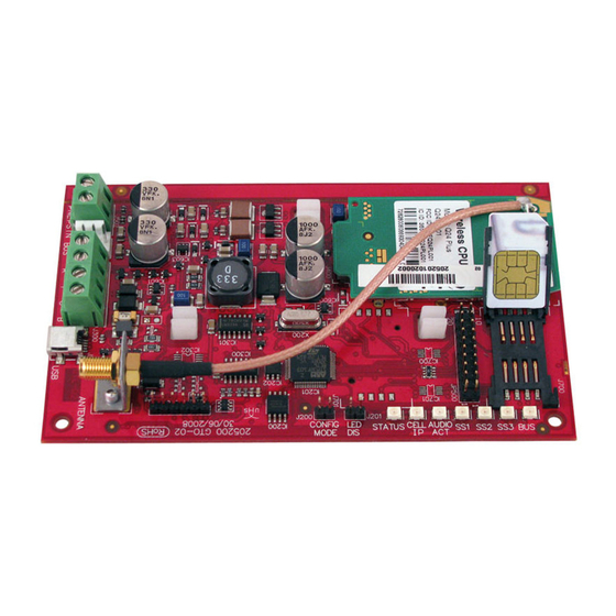
Page 8: Device Overview
SIM card in card holder NOTICE! To conserve power, disable the diagnostic LEDs by placing a jumper plug across the LED DIS jumper pins. Refer to Figure 2.2 for more information. F01U163066 | 01 | 2010.05 Installation and Operation Guide Bosch Security Systems, Inc. -
Page 9: Modes Of Operation
Refer to Figure 3.4, Page 15 Supported control panels: All. Refer to Section 1.4 Control Panel Compatibility, page 6. Table 2.2 PSTN over GSM Mode of Operation Bosch Security Systems, Inc. Installation and Operation Guide F01U163066 | 01 | 2010.05... -
Page 10: Configuration Options
Control Panel, page 17. NOTICE! The configuration options provide temporary connections to the ITS-DX4020-G for configuration purposes only. They are not intended for long-term, or permanent, connection. F01U163066 | 01 | 2010.05 Installation and Operation Guide Bosch Security Systems, Inc. -
Page 11: Installation
Depending on the SIM card used, first-time registration of the SIM card might take up to 3 minutes to complete. During this time, the signal levels displayed by the signal strength LEDS might fluctuate. Bosch Security Systems, Inc. Installation and Operation Guide F01U163066 | 01 | 2010.05... -
Page 12: Insert The Sim Card
The notched edge is away from the hinge, and the contacts are positioned as shown in Figure 3.1. Close the card holder door, and then slide the door away from the hinge to lock it. F01U163066 | 01 | 2010.05 Installation and Operation Guide Bosch Security Systems, Inc. -
Page 13: Mount The Its-Dx4020-G In The Control Panel Enclosure
Magnetic antenna (mount on top of the enclosure or other metallic surface); route the antenna cable through the enclosure knockout ANTENNA connector on ITS-DX4020-G Bosch Security Systems, Inc. Installation and Operation Guide F01U163066 | 01 | 2010.05... -
Page 14: Connect The Its-Dx4020-G To The Control Panel
Bus connection from ITS-DX4020-G to the control panel using the supplied Molex cable Bus connection from the ITS-DX4020-G to the control panel using the bus power terminals Bus power terminals on the control panel F01U163066 | 01 | 2010.05 Installation and Operation Guide Bosch Security Systems, Inc. - Page 15 Bus terminals on the control panel PNL/PSTN connection from ITS-DX4020-G to the control panel Phone terminals on the control panel (connect to the Ring [R] and Tip [T] terminals) Bosch Security Systems, Inc. Installation and Operation Guide F01U163066 | 01 | 2010.05...
-
Page 16: Check Signal Strength
Marginal: -89 dBm to -83 dBm Flash Good: -83 dBm to -77 dBm Very good: -77 dBm to -69 dBm Flash Excellent: > -69 dBm Table 3.1 Signal Strength Levels F01U163066 | 01 | 2010.05 Installation and Operation Guide Bosch Security Systems, Inc. -
Page 17: Configuration
DTMF digit is dialed. NOTICE! Bosch recommends that when using GSM mode, always enter a 10-digit phone number in the control panel. This is because the SIM card might have originated in a different area code from the installation location. - Page 18 Separate each ID or value pair with a line feed (<LF>), a carriage return (<CR> or < ENTER>), or a semi-colon <;>. Due to phone and carrier differences, Bosch recommends using semi-colons to create and send SMS messages. For example, %1;1=4020G;10=Airnet1;14=88;17=2;!.
-
Page 19: Send The Configuration Sms
Observe the LEDs on the ITS-DX4020-G. When all of the LEDs start a scrolling pattern, the ITS-DX4020-G is successfully configured. Refer to Table 4.6 for more information. Bosch Security Systems, Inc. Installation and Operation Guide F01U163066 | 01 | 2010.05... -
Page 20: Exit From Config Mode
PC or laptop. If the ITS-DX4040-G CD-ROM is not available: From your Internet browser, go to http://www.boschsecurity.com to open the Bosch Web site. Select the web site for your region and country. -
Page 21: Install The Usb Driver
Select Install from a list or specific location (Advanced), and click Next. On the resulting Please choose your search and installation options page, select the Search for the best driver in these locations option button. Bosch Security Systems, Inc. Installation and Operation Guide F01U163066 | 01 | 2010.05... - Page 22 Figure 4.3 Browse for Folder Dialog Box Navigate to and highlight the downloaded ITS-DX4020-G.inf file. Click OK and then click Next. The Found New Hardware Wizard Finish page appears. F01U163066 | 01 | 2010.05 Installation and Operation Guide Bosch Security Systems, Inc.
-
Page 23: Install A Communication Program
Select Components page of the wizard, select Compact installation from the drop-down list. Refer to Figure 4.5, Page 23. Figure 4.5 Setup - Tera Term Wizard’s Select Components Page Bosch Security Systems, Inc. Installation and Operation Guide F01U163066 | 01 | 2010.05... -
Page 24: Log Into The Usb Interface
If the ITS-DX4020-G is not connected to the computer, or the USB driver is not installed, the ITS-DX4020-G does not appear in this list. After the connection is established, press [Enter]. The ITS-DX4020-G USB login window opens. F01U163066 | 01 | 2010.05 Installation and Operation Guide Bosch Security Systems, Inc. - Page 25 ITS-DX4020-G by removing the jumper plug from the CONFIG MODE jumpers, and then repeat Steps 3 through 6. Press [Enter] to continue. The USB main menu opens. Refer to Figure 4.7, Page 26. Bosch Security Systems, Inc. Installation and Operation Guide F01U163066 | 01 | 2010.05...
-
Page 26: Usb Main Menu
If you press [Enter] without entering a new value, the current value is unchanged. To go to a specific menu option, enter the appropriate menu item number and press [Enter]. F01U163066 | 01 | 2010.05 Installation and Operation Guide Bosch Security Systems, Inc. - Page 27 Standard for Control Units and Accessories for Fire Alarm Systems, UL 864, certain programming features or options must be limited to specific values or not used at all as indicated in Table 4.9, Page 28. Bosch Security Systems, Inc. Installation and Operation Guide F01U163066 | 01 | 2010.05...
- Page 28 GPRS Transmit 6 to 120 sec (15 sec) Length of time the control panel messages remain buffer lifetime in the in the ITS-DX4020-G buffer before they are discarded. F01U163066 | 01 | 2010.05 Installation and Operation Guide Bosch Security Systems, Inc.
- Page 29 (for example, 10.10.10.1). Select “none” to disable the dynamic DNS server update. Dynamic DNS 1 to 65535 (7702) Enter a DNS server port number, if applicable. Server Port Bosch Security Systems, Inc. Installation and Operation Guide F01U163066 | 01 | 2010.05...
-
Page 30: Polling Configurations
ACK timeout (78 sec). The minimum GPRS session timeout setting is 1 hour; the default 4 hour setting is acceptable. D6x00 Receiver Settings – Control Panel Poll Rate: 60 sec – ACK Wait: 78 sec F01U163066 | 01 | 2010.05 Installation and Operation Guide Bosch Security Systems, Inc. -
Page 31: Medium Security Application
To set the control panel poll rate by the hour, ensure that the D6x00 Receiver has D6200CD V1.35 firmware or later. Because the Bosch D6x00 Receivers only have hours and seconds settings, the receiver would have to be set to 4 hours instead of 3 hours and 30 min. The receiver can only support up to 255 sec maximum for the ACK wait time. -
Page 32: Backup Or Low Security Application (Residential Or Other Once-A-Day Reporting Location)
F01U163066 | 01 | 2010.05 Installation and Operation Guide Bosch Security Systems, Inc. -
Page 33: Sim Card Data Usage
Other factors such as the number of session timeouts can increase data usage. Based on 60 sec polling and 5 events/day, you can expect to use ~5 MB of data per month not including RPS usage. Bosch Security Systems, Inc. Installation and Operation Guide F01U163066 | 01 | 2010.05... -
Page 34: Testing
USB connection. When you first install the LED Disable jumper, the LED flashes the firmware version as a series of three flashes (for example, 1 - 4 - 3 flashes signifies firmware version 1.4.3). F01U163066 | 01 | 2010.05 Installation and Operation Guide Bosch Security Systems, Inc. -
Page 35: Firmware Upgrade
To upgrade the firmware in the ITS-DX4020-G, you must download the latest firmware file from the Bosch Web site to the target PC or laptop, and then use either Hyper Terminal or Tera Term to install the firmware file on the ITS-DX4020-G. - Page 36 13. Click Send to start the firmware upgrade. The Xmodem file send for ITS-DX4020-G dialog box opens and indicates the upgrade progress. Refer to Figure 6.3, Page 37. F01U163066 | 01 | 2010.05 Installation and Operation Guide Bosch Security Systems, Inc.
-
Page 37: Install The Firmware Using Tera Term
– Stop bits: 1 – Flow control: None After the connection is established, press the [Enter] key. The ITS-DX4020-G USB login window opens. Figure 6.4, Page 38. Bosch Security Systems, Inc. Installation and Operation Guide F01U163066 | 01 | 2010.05... - Page 38 11. In the XMODEM Send dialog box, use the Look in: menu to navigate to and select the location to which you downloaded the ITS-DX4020-G binary file. Refer to Figure 6.6, Page 39. F01U163066 | 01 | 2010.05 Installation and Operation Guide Bosch Security Systems, Inc.
- Page 39 During the firmware upgrade process, pauses in the data transfer are normal. During these pauses, the module processes other information. If the process stops for more than 1 min, restart the module and repeat the process. Bosch Security Systems, Inc. Installation and Operation Guide F01U163066 | 01 | 2010.05...
-
Page 40: Troubleshooting
When the LED DIS jumper is applied, the STATUS LED flashes at a slower 4 sec interval to save power. The flashes do not indicate a trouble condition. F01U163066 | 01 | 2010.05 Installation and Operation Guide Bosch Security Systems, Inc. - Page 41 → = Scrolling LEDs, from left to right. = LED’s status is not significant. *Shifting flash = Every other LED flashes simultaneously, creating the shifting flash pattern. Bosch Security Systems, Inc. Installation and Operation Guide F01U163066 | 01 | 2010.05...
- Page 42 → = Scrolling LEDs, from left to right. = LED’s status is not significant. *Shifting flash = Every other LED flashes simultaneously, creating the shifting flash pattern. F01U163066 | 01 | 2010.05 Installation and Operation Guide Bosch Security Systems, Inc.
- Page 43 = Scrolling LEDs, from left to right. = LED’s status is not significant. *Shifting flash = Every other LED flashes simultaneously, creating the shifting flash pattern. Table 7.2 ITS-DX4020-G LED Descriptions Bosch Security Systems, Inc. Installation and Operation Guide F01U163066 | 01 | 2010.05...
-
Page 44: Troubleshooting Procedures
Perform the Factory Defaulting procedure using the USB menu as described in Table 4.8, Page 27. Upgrade the firmware as described in Section 6 Firmware Upgrade, page 35. If the problem continues, replace the ITS-DX4020-G. F01U163066 | 01 | 2010.05 Installation and Operation Guide Bosch Security Systems, Inc. -
Page 45: Radio Registration
GSM Signal Strength LEDs as described in the Signal strength indicators section of Table 7.2, Page 43. Bosch recommends connecting the module to the PC using USB in order to determine if the module is GSM registered on the network, or if the module cannot obtain a GPRS signal. -
Page 46: Control Panel Bus
Remove and replace the configuration jumper and try again. If the format appears correct but the SMS is not accepted, try to send the SMS from a different phone or computer. F01U163066 | 01 | 2010.05 Installation and Operation Guide Bosch Security Systems, Inc. -
Page 47: Firmware Upgrade In Process
Check for complete bus wiring to the control panel. Refer to Section 7.2.8 Control Panel Bus, page 46. If in GSM mode, make sure the data bus wires are not connected or touching any metal surfaces. Bosch Security Systems, Inc. Installation and Operation Guide F01U163066 | 01 | 2010.05... -
Page 48: Radio Initializing Or No Signal Strength
To reduce problems as conditions change, use the highest installation location possible. Bosch Security Systems, Inc. recommends a signal strength level of Good or higher for all installations. Refer to Table 3.1, Page 16 for signal strength measurements. -
Page 49: Marginal Rf Signal
Marginal RF Signal Description: Marginal signal strength: -89 dBm to -83 dBm. Bosch Security Systems, Inc. recommends trying to improve the signal further because this signal strength is near unacceptable levels. Poor weather and other environmental conditions can make this signal unacceptable. This signal level results in a trouble condition if the low signal strength setting for the ITS-DX4020-G is enabled. - Page 50 | Troubleshooting GPRS/GSM IP Communicator F01U163066 | 01 | 2010.05 Installation and Operation Guide Bosch Security Systems, Inc.
- Page 52 Bosch Security Systems, Inc. 130 Perinton Parkway Fairport, NY 14450 www.boschsecurity.com © Bosch Security Systems, Inc., 2010...