Samsung WW90M6 Service Manual
Washing machine drum type
Hide thumbs
Also See for WW90M6:
- User manual (136 pages) ,
- User manual (68 pages) ,
- User manual (136 pages)
Table of Contents
Advertisement
SERVICE
WASHING MACHINE (DRUM)
WW22N6850NX-A2_SM.indb 1
WASHING MACHINE
DRUM TYPE
Basic Model : WW90M6
(WW6800M PROJECT)
Model Name : WW22N6850Q*
(WW6850N PROJECT)
Model Code : WW22N6850QX/A2
(WW6850N PROJECT)
Manual
1. Safety Instructions
2. Features and Specifications
3. Disassembly and Reassembly
4. Troubleshooting
5. PCB Diagram
6. Wiring Diagram
7. Reference
CONTENTS
2018/2/1 17:15:26
Advertisement
Table of Contents

Related Manuals for Samsung WW90M6


Summary of Contents for Samsung WW90M6
- Page 1 WASHING MACHINE DRUM TYPE Basic Model : WW90M6 (WW6800M PROJECT) Model Name : WW22N6850Q* (WW6850N PROJECT) Model Code : WW22N6850QX/A2 (WW6850N PROJECT) SERVICE Manual WASHING MACHINE (DRUM) CONTENTS 1. Safety Instructions 2. Features and Specifications 3. Disassembly and Reassembly 4. Troubleshooting 5. PCB Diagram 6.
-
Page 2: Table Of Contents
CONTENTS 1. Safety instructions ..............1 1-1. -
Page 3: Safety Instructions
1. SAfETy INSTRuCTIONS 1-1. SAfETy INSTRuCTIONS fOR SERvICE ENgINEERS ► Make sure to observe the following instructions to operate the product correctly and safely and prevent possible accidents and hazards while servicing. ► Two types of safety symbols, Warning and Caution, are used in the safety instructions. Hazards or unsafe practices that may result in severe personal injury or death. WARNINg Hazards or unsafe practices that may result in minor personal injury or property damage. CAuTION WARNINg BEfORE SERvICINg... - Page 4 WARNINg WHILE SERvICINg • Check if the power plug and outlet are damaged, flattened, cut or otherwise degraded. 4 If faulty, replace it immediately. Failing to do so may result in electric shock or fire. • Completely remove any dust or foreign material from the housing, wiring and connection parts. 4 This will prevent a risk of fire due to tracking and shorts in advance. • When connecting wires, make sure to connect them using the relevant connectors and check that they are completely connected. 4 Do not use tape instead of the connectors, it may cause fire due to tracking. • Make sure to discharge the PBA power terminals before starting the service. 4 Failing to do so may result in a high voltage electric shock. • When replacing the heater, make sure to fasten the nut after ensuring that it is inserted into the bracket-heater. 4 If not inserted into the bracket-heater, it touches the drum and causes noise and electric leakage. WARNINg AfTER SERvICINg • Check the wiring. 4 Ensure that the wiring can not be damaged by any sharp edges or moving parts. • Check for any water leakage. 4 Perform a test run for the washing machine using the standard course and check whether there is any water leakage through the floor section or the pipes. • Do not allow consumers to repair or service any part of the washing machine themselves. 4 This may result in personal injury and shorten the product lifetime.
- Page 5 CAuTION BEfORE SERvICINg • Do not sprinkle water onto the washing machine directly when cleaning it. 4 This may result in electric shock or fire, and may shorten the product lifetime. • Do not place any containers with water on the washing machine. 4 If the water is spilled, it may result in electric shock or fire. This will also shorten the product lifetime. • Do not install the washing machine in a location exposed to snow or rain. 4 This may result in electric shock or fire, and shorten the product lifetime. • Do not press a control button using a sharp tool or object. 4 This may result in electric shock or damage to the product. CAuTION WHILE SERvICINg • When wiring a harness, make sure to seal it completely so no liquid can enter. 4 Take care when disconnecting connectors, do not use excessive force as this may damage the connector. • Check if there is any residue that shows that liquid entered the electric parts or harnesses. 4 If any liquid has entered into a part, replace it or completely remove any remaining moisture from it. • If you need to place the washing machine on its back for servicing purposes, place a support(s) on the floor and lay it down carefully so its side is on the floor. 4 Do not lay it down on its front. This may result in the inside tub damaging parts. Safety Instructions _ 3 WW22N6850NX-A2_SM.indb 3 2018/2/1 17:15:26...
- Page 6 CAuTION AfTER SERvICINg • Ensure that all components are reassembled correctly and are safe before connecting the appliance to the mains supplies. • Check the insulation resistance. 4 Disconnect the power cord from the power outlet and measure the insulation resistance between the power plug and the grounding wire of the washing machine. The value must be greater than 10MΩ when measured with a 500V DC Megger • Check whether the washing machine is level in relationship with the floor. Check whether it is installed firmly on the floor. 4 Vibrations can shorten the lifetime of the product. 4 _ Safety Instructions WW22N6850NX-A2_SM.indb 4 2018/2/1 17:15:27...
-
Page 7: Features And Specifications
2. fEATuRES AND SPECIfICATIONS 2-1. CONCEPT ■ COMMON fEATuRES features Description Q-Drive • Innovative Q-Drive technology reduces the washing time by up to 50%* and cuts energy use by 20%*, without compromising the cleaning performance. The motion of the Drum moves clothes from top to bottom, while a pulsator creates a wide and intense shower, so it quickly, gently and thoroughly removes dirt. ※ Test Condition : eCotton 60℃, half load * Tested by Intertek Smart Control • Smart Control lets you remotely control and monitor your washing using a smartphone App*. At any time and from anywhere, you can quickly start or pause it and keep an eye on program selections, time remaining and finishing alerts. And it will even diagnose errors and provide the best solution. *Available on iPhones and Android devices. A Wi-Fi connection is required. Features and Specifications _ 5 WW22N6850NX-A2_SM.indb 5 2018/2/1 17:15:28... - Page 8 Description Eco Bubble • Before the normal cycle begins, the unique bubble generator starts working. It helps dissolve and activate the detergent using air and water to generate bubbles that penetrate faster and more evenly throughout the wash load. This brings the detergent into contact with each fiber in the load. ※ Based on internal bench top test water temp.15℃, IEC60456 EU standard detergent, grease soil swatch (EMPA120). Bubble Soak • With the simple touch of a button the Samsung washing machine’s Bubble Soak technology helps remove a wide variety of normally stubborn stains. It adds an extra phase to a normal washing cycle in which clothes are thoroughly soaked in active bubbles, so any dirt and stains are loosened and can be removed much more effectively. 6 _ Features and Specifications WW22N6850NX-A2_SM.indb 6 2018/2/1 17:15:29...
-
Page 9: Specifications
2-2. SPECIfICATIONS Type front loading washing machine Model name WW22N6850Q* Dimensions W600 × D600 × H850 (mm) Water pressure 50-800 kPa Net weight 77 kg Washing 120 V 200 W Washing and 120 V 1150 W Power heating consumption Spin 120 V 550 W Drain 120 V 80 W Spin revolutions 1400 rpm Features and Specifications _ 7 WW22N6850NX-A2_SM.indb 7... - Page 10 D1115 H850 W600 D600 Dimension Height-Overall (A) Width (B) Depth (C) Depth with door open 90° (D) 1115 8 _ Features and Specifications WW22N6850NX-A2_SM.indb 8 2018/2/1 17:15:29...
-
Page 11: Comparing Specifications With Existing Models
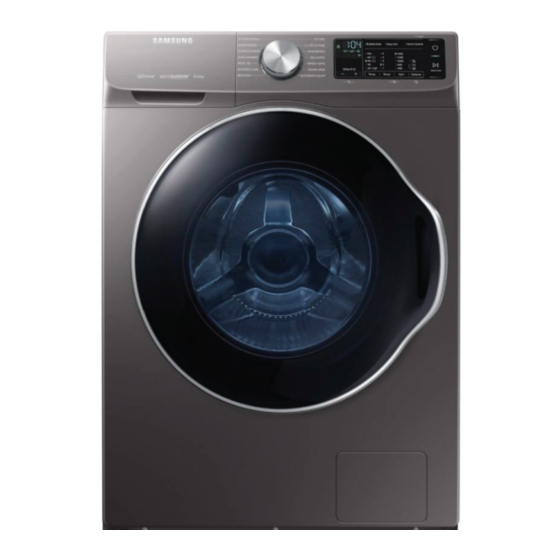
2-3. COMPARINg SPECIfICATIONS WITH EXISTINg MODELS (★) : Special models only Project WW6850N WW6800M Model Name WW22N6850Q* WW9*M64* Image Blue Crystal, Add Wash , Feature Blue Crystal, Smart Control, Q-Drive Smart Control, Q-Drive Capacity 9.0 kg /8.0kg Drum Volume 63 L 63 L Max Rpm 1400 1400 DIM, DIM, Motor DC93-00586G, 5.7Ω±5% DC93-00586D, 5.7Ω±5% (25℃) (25℃) Control Sys General General Weight Detection 3Stage 3Stage Main Spec... -
Page 12: Options Specifications
2-4. OPTIONS SPECIfICATIONS Unit Part Code Figure Description To remove the shipping bolts Bolt Spanner DC60-00104A To adjust the leveling leg DC97-15648A (COLD) Assy Hose Cold only 1, To setup water supply. Water Cold+Hot 2(★) DC97-15648B (HOT) ASSY HOSE WATER DC62-00079A To setup water supply. 1(★) (Aqua-Stop) To explain the product Manual Users DC68-03645B operation and installation Cap Fixer DC67-00307A To cover the holes To cover the hole from which you removed the Cap Fixer DC67-00208B power cord at the back of the product. Hose Hanger DC62-10278A To secure the drain hose. -
Page 13: Disassembly And Reassembly
3. DISASSEMBLy AND REASSEMBLy 3-1. TOOLS fOR DISASSEMBLy AND REASSEMBLy Tool Type Remarks Heater(1),Tub(12), Fixer screw(5), Motor(2), 10mm Balance(9) Box driver Shock Absorber (2 holes each in left/right), 13mm Damper(2), Damper(friction 2) 19mm Pulley(1) 10mm Replaced by box driver Double-ended 13mm spanner 19mm A Tool for protecting empty turning of bolt or abrasion from using box driver Vice pliers For disassembly of Spin drum Others Common tools for servicing (screwdriver, nipper, long nose pliers) Torque wrench The Tool for assembly of heater and Tub Disassembly and Reassembly _ 11 WW22N6850NX-A2_SM.indb 11 2018/2/1 17:15:30... -
Page 14: Standard Disassembly Drawings
3-2. STANDARD DISASSEMBLy DRAWINgS ► This is a standard disassembly diagram and may differ from the actual product. Use this material as a reference when disassembling and reassembling the product. Part figure Description 1. Remove the 2 screws holding the Top Cover at the back of the unit. 2. Remove the top-cover by lifting it up after pulling it back about 15mm. Assy Cover Top Noise filter Water valve 3. Then, the Water (Pressure) Sensor, Noise Filter and Water Valve can be replaced. Sensor pressure 12 _ Disassembly and Reassembly WW22N6850NX-A2_SM.indb 12 2018/2/1 17:15:32... - Page 15 Part figure Description 1. Remove the 2 screws holding the front operating panel. 2. Remove the screws at the top of the ASSY- PANEL CONTROL. Sub-PCB Panel 3. Hold the ASSY-PANEL CONTROL while pulling it upwards and release the terminals to remove it. 5. Release the hooks and screws to remove the PCB for repair / replacement. Disassembly and Reassembly _ 13 WW22N6850NX-A2_SM.indb 13 2018/2/1 17:15:33...
- Page 16 Part figure Description 1. Remove 1 screw. 2. Remove the Band-ring. Assy Housing- Drawer 3. Separate the water supply valve wire. 4. Remove the screws holding the water supply valve. 14 _ Disassembly and Reassembly WW22N6850NX-A2_SM.indb 14 2018/2/1 17:15:34...
- Page 17 Part figure Description 1. Using long nose pliers, pick up one of the rings on Wire-Diaphragm which connect the spring and the wire ends. then Separate the Wire-Diaphragm from the FRAME-FRONT and Disconnect the Diaphragm. 2. Remove the 2 screws holding the FRAME- FRONT. 3. Remove the 3 screws holding the bottom frame front of the FRAME-FRONT. 4. Disconnect the terminal for the DOOR- 120V LOCK switch. Disassembly and Reassembly _ 15 WW22N6850NX-A2_SM.indb 15 2018/2/1 17:15:34...
- Page 18 Part figure Description • Unfasten the 4 screws that hold the back cover in place. Remove the back cover by Cover-Back sliding it down. (When assembling, slide the back cover up.) 1. Remove the Cover back . 2. Separate the belt and then assembly it. 3. Check if the belt position is at the center of Belt the Pulley. Assembling the belt Place the belt around the Motor-Pulley (①) and then over the Pulley (②). 16 _ Disassembly and Reassembly WW22N6850NX-A2_SM.indb 16 2018/2/1 17:15:35...
- Page 19 Part figure Description 1. Separate the blet. 2. Remove the 2 screws and connector. Separate the cover heater. BLDC Motor 3. Separate the bolts of motor. 4. Separate the motor. Caution When installing the Belt around the Motor Pulley, the bottom of the belt must be located on the second tooth of the motor pulley of the Motor Pulley. Disassembly and Reassembly _ 17 WW22N6850NX-A2_SM.indb 17 2018/2/1 17:15:36...
- Page 20 Part figure Description 1. Separate the Assy Cover-Top. 2. Separate the water supply valve wire. Water Supply valve 3. Remove the screws holding the water supply valve. Water valve Noise filter 1. Separate the Assy Top-Cover. Sensor pressure 2. Disconnect the wire between the Water Level Sensor PRESSURE HOSE and the water level sensor for repair / replacement. 3. Push the clip of the water level sensor behind sensor to one side of the frame and pull it out to remove it. 18 _ Disassembly and Reassembly WW22N6850NX-A2_SM.indb 18 2018/2/1 17:15:37...
- Page 21 Part figure Description 1. Separate top cover & panel control. 2. Open the door, removing the two screws Assy Door holding the door hinge. 3. Seperate the door. Disassembly and Reassembly _ 19 WW22N6850NX-A2_SM.indb 19 2018/2/1 17:15:37...
- Page 22 Part figure Description 1. Remove the Frame Front. Drain Pump 2. Remove the remaining water through the drainage hose. Place a bowl under the drainage hose, hose to catch any water that may flow out. 3. Remove the 2 screws holding the drain pump. 20 _ Disassembly and Reassembly WW22N6850NX-A2_SM.indb 20 2018/2/1 17:15:39...
- Page 23 Part figure Description 5. Disconnect the terminal and Holder. 6. Release the BAND RING (3EA) and Drain Pump remove the HOSE (3EA). 7. Push the TUB inward slightly to remove the PUMP. Pump wire harness is connected to main wire harness. Drain Pump 4 Check Points for Troubleshooting 1. S eparate the Drain Filter and check if any alien substances are inside the pump (e.g. coins, buttons .., etc.) → Remove these if found. 2. C heck if the wire driving the pump has come loose → Take the relevant countermeasure if necessary. 3. W hen water leaks, check the assembly status of the Clamp Hose, and Cap Drain → Take the relevant countermeasure if necessary. Turn the filter counterclockwise to remove the remaining water. Disassembly and Reassembly _ 21 WW22N6850NX-A2_SM.indb 21 2018/2/1 17:15:40...
- Page 24 Part figure Description 1. Open the Door. Remove the Wire Diaphragm and remove it from The Front Frame. For easier disassembly, remove the spring from the lower part of the Diaphragm with a (-) screwdriver. Since the Diaphragm can be damaged when removing it. Use a Longnose plier and remove it slowly in one direction. Door-Lock S/W 2. Remove the 2 screws. 3. Remove the screw holding the Door-Lock S/W. Remove the Door-Lock S/W. Remove the connection wire.(Remove the connector after releasing it by pressing the catch.) 1. Remove the Frame Front. Door S/W 2. Remove the 1 screw. 3. Remove the screw holding the Door S/W. Remove the Door S/W. Remove the connection wire.(Remove the connector after releasing it by pressing the catch.) 22 _ Disassembly and Reassembly WW22N6850NX-A2_SM.indb 22 2018/2/1 17:15:42...
- Page 25 Part figure Description 1. Disconnect two wire connectors. Leakage Sensor (OPTION) 2. Remove the 2 screws. Disassembly and Reassembly _ 23 WW22N6850NX-A2_SM.indb 23 2018/2/1 17:15:43...
- Page 26 Part figure Description 1. Separate the Back Cover. Heater 2. Separate the Belt pulsotor. 3. Remove the 2 screws and connector. Separate the cover heater. 24 _ Disassembly and Reassembly WW22N6850NX-A2_SM.indb 24 2018/2/1 17:15:44...
- Page 27 Part figure Description 4. Remove the nut holding the heater and separate the Heater. Use box Drivers (Socket size: 10mm) 5. Remove the Heater from the Tub Caution Make sure to insert the Heater into the Heater correct position of the bracket inside the Tub when reassembling it. Otherwise, there is a danger of a fire. Make sure to push it inwards until the packing part comes into the Tub completely when reassembling it so that the packing part is completely stuck to the Tub. Fasten the holding nut with a force of 5Kgf/ cm2. If the nut is not fastened properly, there is a danger of water leaking. Disassembly and Reassembly _ 25 WW22N6850NX-A2_SM.indb 25 2018/2/1 17:15:45...
- Page 28 Part figure Description 1. Remove the Cover Back. 2. Remove the 2 screws. Assy PCB Main 3. Push the TUB inward slighhtly to remove the PBA. 4. S eparate the guide cover pcb and remove the wire harness. 26 _ Disassembly and Reassembly WW22N6850NX-A2_SM.indb 26 2018/2/1 17:15:46...
- Page 29 Part figure Description 1. Remove the Cover Back. 2. Separate the blet. 3. R emove the 2 screws and connector. RSeparate the cover heater. Assy Kit 4. Separate the motor. 5. Remove the 2 screws on the back of frame. Disassembly and Reassembly _ 27 WW22N6850NX-A2_SM.indb 27 2018/2/1 17:15:48...
- Page 30 Part figure Description 6. Separate the Cover PCB。Remove the wire harness from the hook. Assy Kit 7. Separate Assy Kit and the connector. 4 Check Points for Troubleshooting 1. Check whether there is any error in applying the power. 2. Check the voltage between the DC 5V and GND terminals. 3. If an information code occurs when there is no characteristic code in the electric harnesses, check these information code: Replacement of the 3C : The resistance of motor(U-V/V-W/W-U) is 4.5 to 7.0 Ω Main PCB HC/HC1 : The resistance of heater(for 2000W unit) is 25.19 to 27.84 Ω DC1 : The resistance of door switch is 500 to 1,500 Ω DC3/DDC : The resistance of door switch is 31.57 to Ω 61.57 5C : The resistance of drain motor is 182 to 222 Ω...
-
Page 31: Troubleshooting
4. TROuBLESHOOTINg 4-1. INfORMATION CODE ► When an abnormal condition occurs, melody sounds and displays Info. code indications as shown in the following Info. codes are shown until the status has cleared. Information Information Causes Corrective Actions Type Code - The part of the hose where the water level sensor is located is damaged (punctured). - Page 32 Information Information Causes Corrective Actions Type Code - The signals between the sub and main PBAs are not sensed because of a communications error. • M ain PCB and Sub PCB Signal - Check the connector connections between the sub Detection fault Communication and main PBAs carefully. → Check for incorrect or • M ain PCB and Sub PCB wire loose connections, etc. connection fault - Remove the sub PBA C/Panel and check for any faulty soldering. - A button other than the Power button is continually • When pressed Power button pressed (for more than 30 seconds). SWITCH • W hen pressed button except - Deformation of an internal plastic injection part. for power button (Main relay ) - A screw for assembling the sub PBA is tightened • Main PCB relay fault too much.
- Page 33 Information Information Causes Corrective Actions Type Code - Heater engagement fault. (out of place) - The air hose is out of place and water leakage occurs during the spin cycle. - The tub back at the safety bolts fixing part is broken. - Water leakage occurs at the front with foaming because of too much detergent. • Check Water Leakage - Water leakage occurs because the connecting • D V CASE foreign material hose to the detergent drawer is connected occurs incorrectly. Water Leakage • L eakage of the product inside - The drain pump filter cover is engaged incorrectly. the hose and parts molded - Water leakage occurs at the drain hose. problem - The duct condensing holding screws are worn. - The nozzle-diaphragm is engaged in the opposite direction or the rubber packaging is omitted.
- Page 34 Information Information Causes Corrective Actions Type Code - As laundry causes this error, check the laundry. UNBALANCE • This occurs by laundry. - Find the reason for the unbalance and solve it as directed in the user manual. • C heck the consumer’s power conditions. : Make sure to check the operating voltage. • C onnect a tester to the internal power terminals during the Boil or Dry operations and - Power condition fault. observe the washing machine’s - An error occurs when under or over voltage is operation carefully. supplied. Power : Check the voltages. (9C) (An error occurs when under or - Plug receptacle is used over voltage is supplied.) - Main PBA fault (sometimes) : Check whether a plug receptacle is used. When the connecting wire is 1m, a...
-
Page 35: Diagnostic Code & Corrective Action
4-2. DIAgNOSTIC CODE & CORRECTIvE ACTION ► These are common troubleshooting procedures for each drum-type washer error mode. For detailed information, refer to the general repair scripts. Infor- Information mation Causes Corrective Actions Description of Photo Type Code • Check the water level sensor Check the water level sensor frequency. terminal connections and - C heck it after the water level sensor and the contacts. connector are connected. • Water level sensor fault • An error occurs if an incorrect - Frequency: Approx. 25.0 KHz with no load • Incorrect connections of the water level sensor is used. Make water level sensor terminal sure to check the material code. - Page 36 Infor- Information mation Causes Corrective Actions Description of Photo Type Code 1. Check the resistance for the water supply valve. Resistance: 3.6 to 4.4 kΩ between two terminals • If the water supply valve has a of each solenoid. wire disconnected, replace it. • Water supply value fault • Check whether the water supply • Main PCB fault valve is clogged with foreign material and whether water is • Freezing in the winter season supplied continually. Water Supply Check the water supply valve • Check whether no water is whether only cold model or 2. Check whether there is foreign material at the supplied because of freezing in hot and cold model Incorrect inlet filter of water supply valve. the winter season. connection can occur an error • If the PBA relay operates abnormally, replace the PBA.
- Page 37 Infor- Information mation Causes Corrective Actions Description of Photo Type Code • Check the wire connections and terminal contacts between the main and inverter PBAs. • The diagnosis of the DR • Check for disconnected wires. communication error. • If the main or Inverter PBA’s communication circuit is faulty, replace it. • Check the wire connections and terminal contacts between the sub and main PBAs. • Check for disconnected wires. • The diagnosis of the Wifi Communication • Check whether the sub PBA communication error. is short-circuited because of moisture. • I f the main PBA’s communication circuit is faulty, replace it.
- Page 38 Infor- Information mation Causes Corrective Actions Description of Photo Type Code Check the resistance on the Heater. (For faulty features) • This error occurs if the water Temperature is more than 50 ˚C in Check the voltages both terminals of the Heater draining. Check the temperature. while washing. • If the water temperature is normal, Check 25.19 ~ 27.84Ω on both terminals and the • Washing Temperature sensor this error is due to a temperature voltage of the Heater. fault sensor fault. Replace the washing Cooling • Description of PL hazard heater. prevention When replacing the washing heater, take care to prevent water leakage. ▶ Type1 The resistance of Nos. 3 and 5 of the DOOR LOCK SWITCH must be approximately 1000Ω±50%. • If a dC error occurs, check whether it occurs during the Boil cycle.
- Page 39 Infor- Information mation Causes Corrective Actions Description of Photo Type Code Check resistance values normally displayed when you press the • DDC/ddC means add door is door switch opened Close the add door. button. • Check add door switch, Barrier, Lock module’s movement is • Add door switch fault Check door lock DDC/ operate normally. check Open motor resistance. detection switch and Barrier ‘s Door • Main PCB fault (1-2 pin Lock pillars coming down while • Bending connector 46.57±15Ω) pressing in operation normally. • Main PBA door detection circuit is Lock stroke fault or connector combination.
- Page 40 Infor- Information mation Causes Corrective Actions Description of Photo Type Code • Check the connections for the washing heater temperature • Washing temperature sensor sensor connector. fault • If the washing heater • Dry temperature sensor fault temperature sensor has a • Faulty and incorrect functional error, replace it. Temperature connections of the dry - A tC1 error occurs. condensing sensor Sensor • Check the connections for the • Main PCB fault dry heater temperature sensor connector. • Freezing in the winter season •...
-
Page 41: Problem Check Point
4-3. PROBLEM CHECK POINT PROBLEM SOLuTION • Make sure the washing machine is plugged in. • Make sure the door is properly closed. The washing machine won’t start. • Make sure the water tap is open. • Tap Start or Press Start/Pause button again. • Open the water tap fully. • Make sure the water supply hose is not frozen. Water supply is insufficient, or no water is supplied. • Make sure the water supply hose is not kinked or clogged. • Clean the filter on the water supply hose. • Make sure the washing machine is installed on a level floor. If the floor is not level, use the leveling feet to adjust the level. The washing machine vibrates badly, • Make sure that the shipping bolts are removed. or makes noise. • Make sure the washing machine is not touching any other object. • Make sure the laundry load is balanced. • Make sure the drain hose is straightened all the way to the drain system. The washing machine does not drain and/or spin. • Make sure the debris filter is not clogged. • Press the Start/Pause button to stop the washing machine. • The door stays locked as long as the washing machine is still hot inside The door won’t open. after a heating operation. • It may take several seconds to disengage the door lock mechanism. Button Check • bC occurs. Refer the bC troubleshooting. Troubleshooting _ 39 WW22N6850NX-A2_SM.indb 39 2018/2/1 17:15:51... -
Page 42: Pcb Diagram
5. PCB DIAgRAM 5-1. MAIN PCB DIAgRAM ► This Document can not be used without Samsung’s authorization. : Pin 1 ● Location Part No. function Description POWER SUPPLY RELAY Supply AC Power to All Loads HEATER RELAY Supply power to Heater CN11 POWER/DOOR LOCK TERMINAL Supply AC Power and door lock sensing CN300 ADD DOOR CONTROL TERMINAL Control the Add Door CN10 DRIVING SECTION TERMINAL Signal Output for door lock, water valve, drain pump and bubble pump. CNS801 COMMUNICATION TERMINAL Communicate with SUB PBA & INVERTER PBA CNS202 PROGRAM UPDATE TERMINAL Update the Software of Main PBA CN803 Drum Light TERMINAL Signal Output for Drum Light CNS502 SENSING TERMINAL... -
Page 43: Detailed Descriptions Of Contact Terminals (Main Pba)
5-2. DETAILED DESCRIPTIONS Of CONTACT TERMINALS (MAIN PBA) ► This Document can not be used without Samsung’s authorization. ► CNS502 1. GND 2. Door open Check 3. Leakage Sensing ► CN803 4. Dry air Temperature 1. RX to LCD 6. LCD Reset 5. Dry duct Temperature 2. TX to LCD 7. Start SW 6. Water Temperature 3. 12V 8. Power SW 7. Water level out sensing 4. GND 9. Drum Light 8. Water level in sensing 5. 5V 10. -
Page 44: Inverter Pcb Diagram
5-3. INvERTER PCB DIAgRAM ► This Document can not be used without Samsung’s authorization. : Pin 1 ● Location Part No. function Description CNP102 POWER SUPPLY TERMINAL Supply AC Power to Inverter(N) CNP101 POWER SUPPLY TERMINAL Supply AC Power to Inverter(L) CNP902 MOTOR DRIVE TERMINAL(DRUM) Motor Signal Output(DRUM) CNP901 MOTOR DRIVE TERMINAL(PULSATOR)) Motor Signal Output(PULSATOR) CNS801 COMMUNICATION TERMINAL Communicate with MAIN PBA CNP202 PROGRAM UPDATE TERMINAL Update the Software of Inverter PBA 42 _ PCB Diagram WW22N6850NX-A2_SM.indb 42 2018/2/1 17:15:53... - Page 45 INvERTER PCB DIAgRAM (Cont.) ► This Document can not be used without Samsung’s authorization. ► CNP202 1. 5V 2. RXD_PROGRAM 3. TXD_PROGRAM ► CNS801 4. GND 1. RXD(from Main) 5. MODE 2. TXD(to Main) 6. N.C 7. RESET(N.C) 3. GND ► CNP901 (PULSATOR) ► CNP102 1. Motor U Phase Signal 1. LI_IN 2. Motor V Phase Signal 3. Motor W Phase Sign ► CNP101 ► CNP902 (DRUM) 1. N.C 1. Motor W Phase Signal 2. NE_IN 2. Motor V Phase Signal 3. Motor U Phase Signal PCB Diagram _ 43 WW22N6850NX-A2_SM.indb 43...
-
Page 46: Sub Pcb Diagram
5-4. SuB PCB DIAgRAM ► This Document can not be used without Samsung’s authorization. Location Part No. function Description CN802 WiFi Communication UART Communication with WiFi CN801 Main Communication UART Communication with Main CN502 Mems Sensor Communication SPI Communication with Mems Sensor CN501 Touch Sensor Communication I2C Communication with Touch Sensor CN201 Flash Writing Sub Micom on board writing connector 44 _ PCB Diagram WW22N6850NX-A2_SM.indb 44 2018/2/1 17:15:54... - Page 47 SuB PCB DIAgRAM (Cont.) ► This Document can not be used without Samsung’s authorization. ► CN802 ► CN801 ► CN502 ► CN501 WiFi Communication Main Communication CN502 MEMS Sensor Communication Touch Sensor Communication 1. RX (From WiFi) 1. RX (From Main PBA) 1. +3.3V 1. N.C 2. TX (To Sub PBA) 2. TX (To WiFi) 2. CS1 2. 12V input for Touch 3. WiFi Enable 3. Reset 3. MISO 3. GND 4. GND 4. 5V 4. MOSI 4.
-
Page 48: Assy Pba Service Bom
5-5. ASSy PBA SERvICE BOM Service BOM (SA: SERVICE AVAILABLE, SNA: SERVICE NOT AVAILABEL) SvC_ Code No. Description Specification Code FWM_INV,MK_ DC92-02140D ASSY PCB MAIN PJT,160*121,Y,Washer,110V,Non-Add- Wash,Super-Speed,Bubble,STANDARD DC92-02139B ASSY KIT FWM_INV,MK_PJT,Washer,110V,Standard FWM_INV,MK_ 1-1-1 DC92-02138H ASSY PCB DISPLAY PJT,292*80,9kg,1400rpm,6000 jog,America,STANDARD 46 _ PCB Diagram WW22N6850NX-A2_SM.indb 46 2018/2/1 17:15:57... -
Page 49: Wiring Diagram
6. WIRINg DIAgRAM 6-1. WIRINg DIAgRAM ► This Document can not be used without Samsung’s authorization. REfERENCE INfORMATION BLACK BLUE GREEN GRAY NATURAL ORANGE PINK SKYBLU SKYBLUE VIOLET WHITE YELLOW Wiring Diagram _ 47 WW22N6850NX-A2_SM.indb 47 2018/2/1 17:15:57... -
Page 50: Reference
7. REfERENCE 7-1. WW6850N PROJECT NAME ► Feature3 (display,Wifi,depth) ► Body & Display Color Code Wifi Type Code Body Display Full Touch LCD_9000H ● White Black(blue) or LCD Color LCD_8000H ● Silver Black(blue) or LCD ► Project 7000 '15 ● Inox Black(blue) or LCD ► Capacity 6000 '15 ● Black STS Black(blue) or LCD Code Year Code Content 6000 '15 Gold Black(blue) or LCD... -
Page 51: Terminology
7-2. TERMINOLOgy The pump that drains the water from the washing machine generated while the 1. Drain Pump washing machine is running The heater is located on the tub inside the washing machine. It heats the water to 2. Heater increase wash efficiency. Detects whether the door of the washing machine is open or closed if the door is open 3. Door Lock Switch while the washing machine is running the cycle is temporary stopped. 49 _ Reference WW22N6850NX-A2_SM.indb 49 2018/2/1 17:15:57... - Page 52 (gLOBAL SERvICE PARTNER NETWORK) Area Web Site Europe, CIS, Mideast & Africa gspn1.samsungcsportal.com Asia gspn2.samsungcsportal.com North & Latin America gspn3.samsungcsportal.com China china.samsungportal.com This Service Manual is a property of Samsung Electronics Co.,Ltd. © 2018 Samsung Electronics Co.,Ltd. All Any unauthorized use of Manual can be punished under applicable rights reserved. International and/or domestic law. Printed in Korea WW22N6850NX-A2_SM.indb 50 2018/2/1 17:15:58...