Table of Contents
Advertisement
Quick Links
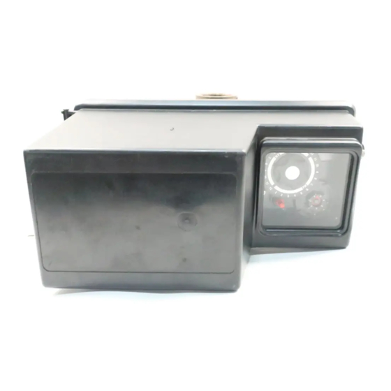
Fleck 3150 Downflow
Service Manual
TABLE OF CONTENTS
JOB SPECIFICATION SHEET ...............................................1
INSTALLATION ......................................................................2
START-UP INSTRUCTIONS ..................................................2
3200 TIMER SETTING PROCEDURE ...................................3
3210 TIMER SETTING PROCEDURE ...................................4
SETTING PROCEDURE (DOWNFLOW) ...............................5
3200 TIME CLOCK TIMER ASSEMBLY .................................6
3210 METER DELAYED TIMER ASSEMBLY ........................7
3220 METER IMMEDIATE TIMER ASSEMBLY .....................8
3230 REMOTE START TIMER ASSEMBLY ...........................9
CONTROL VALVE ASSEMBLY ..............................................10
CONTROL DRIVE ASSEMBLY ..............................................12
FLOW CONTROL ASSEMBLY ...............................................14
2" BRASS METER ASSEMBLY ..............................................17
SERVICE VALVE OPERATOR ASSEMBLY ..........................18
2350 SAFETY BRINE VALVE.................................................19
GENERAL SERVICE HINTS FOR METER CONTROL .........20
TROUBLESHOOTING ...........................................................21
WATER CONDITIONER FLOW DIAGRAMS .........................22
FLOW DATA & INJECTOR DRAW RATES ...........................23
DIMENSIONAL DRAWING .....................................................24
SYSTEM #4 ...........................................................................25
SYSTEM #5 ...........................................................................25
SYSTEM #6 ...........................................................................25
SYSTEM #7 ...........................................................................25
VALVE WIRING ......................................................................26
SERVICE ASSEMBLIES ........................................................32
JOB SPECIFICATION SHEET
Job Number: ___________________________________________________
Model Number: _________________________________________________
Water Hardness: _______________________________________ ppm or gpg
Capacity Per Unit: _______________________________________________
Mineral Tank Size:
________ Diameter: ________ Height: _________
Salt Setting per Regeneration: _____________________________________
1. Type of Timer:
A. 7 Day or 12 Day
B. Meter Initiated
2. Downflow:
Upflow
3. Meter Size:
A. 3/4" Std Range (125 - 2,100 gallon setting)
B. 3/4" Ext Range (625 - 10,625 gallon setting)
C. 1" Std Range (310 - 5,270 gallon setting)
D. 1" Ext Range (1,150 - 26,350 gallon setting)
E. 1-1/2" Std Range (625 - 10,625 gallon setting)
F. 1-1/2" Ext Range (3,125 - 53,125 gallon setting)
G. 2" Std Range (1,250 - 21,250 gallon setting)
H. 2" Ext Range (6,250 - 106,250 gallon setting)
I.
3" Std Range (3,750 - 63,750 gallon setting)
J. 3" Ext Range (18,750 - 318,750 gallon setting)
K. Electronic _________ Pulse Count ________ Meter Size _______
4. System Type:
A. System #4: 1 Tank, 1 Meter, Immediate, or Delayed Regeneration
B. System #4: Time Clock
C. System #4: Twin Tank
D. System #5: 2-5 Tanks, Interlock Mechanical
2-4 Tanks, Interlock Electronic
Meter per unit for Mechanical and Electronic
E. System #6: 2-5 Tanks, 1 Meter, Series Regeneration, Mechanical
2-4 Tanks, 1 Meter, Series Regeneration, Electronic
F. System #7: 2-5 Tanks, 1 Meter, Alternating Regeneration,
Mechanical
2 Tanks only, 1 Meter, Alternating Regeneration,
Electronic
G. System #9: Electronic Only, 2-4 Tanks, Meter per Valve, Alternating
H. System #14: Electronic Only, 2-4 Tanks, Meter per Valve. Brings
units on and offline based on flow.
5. Timer Program Settings:
A. Backwash: ___________________________________ Minutes
B. Brine and Slow Rinse: __________________________ Minutes
C. Rapid Rinse: _________________________________ Minutes
D. Brine Tank Refill: ______________________________ Minutes
E. Pause Time: __________________________________ Minutes
F. Second Backwash: ____________________________ Minutes
6. Drain Line Flow Control: ______________________________gpm
7. Brine Line Flow Controller: ____________________________gpm
8. Injector Size#: ____________________________________________
9. Piston Type:
A. Hard Water Bypass
B. No Hard Water Bypass
Upflow Variable
16504 Rev F
OC11
Advertisement
Table of Contents

Related Manuals for Pentair Fleck 3150 Downflow


Summary of Contents for Pentair Fleck 3150 Downflow
-
Page 1: Table Of Contents
Fleck 3150 Downflow Service Manual TABLE OF CONTENTS JOB SPECIFICATION SHEET JOB SPECIFICATION SHEET ..........1 Job Number: ___________________________________________________ Model Number: _________________________________________________ INSTALLATION ..............2 Water Hardness: _______________________________________ ppm or gpg START-UP INSTRUCTIONS ..........2 Capacity Per Unit: _______________________________________________ 3200 TIMER SETTING PROCEDURE ........3... -
Page 2: Installation
7. Put salt in the brine tank. foreign material (usually solder) that may have resulted NOTE: Do not use granulated or rock salt. from the installation. Once clean, close the water tap. 2 • OC11 Fleck 3150 Downflow... -
Page 3: 3200 Timer Setting Procedure
7. Push the red button and locate the pointer one more time to ensure the desired regeneration time is correct. 8. Reset the time of day and restore power to the unit. 61502-3200 Rev A Figure 2 Fleck 3150 Downflow OC11 • 3... -
Page 4: 3210 Timer Setting Procedure
NOTE: The program wheel to the left may be different than the program wheel on the product. NOTE:To set meter capacity rotate manual knob one - 360° revolution to set gallonage. 61502-3200 Rev A Figure 3 4 • OC11 Fleck 3150 Downflow... -
Page 5: 3200, 3210 Regeneration Cycle Program Setting Procedure (Downflow)
2. To change the length of rapid rinse time, add or remove pins at the higher numbered end of this section as required. The number of pins times two equals the rapid rinse time in minutes. Fleck 3150 Downflow OC11 • 5... -
Page 6: 3200 Time Clock Timer Assembly
17 ....1 ..15424 ....Spring, Detent, Timer ......61420-04 ...Program Wheel, Gear Assy, 18 ....1 ..15066 ....Ball, 1/4”, Delrin Softener, 2 Min Per Pin 19 ....1 ..15465 ....Label, Caution *Call your distributor for Part Number 6 • OC11 Fleck 3150 Downflow... -
Page 7: 3210 Meter Delayed Timer Assembly
*Call your distributor for Part Number 22 ....1 ..14276 ....Spring, Meter, Clutch 23 ....1 ..14253 ....Retainer, Clutch Spring 24 ....3 ..11384 ....Screw, Phil, 6-32 x 1/4 25 ....1 ..13881 ....Bracket, Hinge Timer Fleck 3150 Downflow OC11 • 7... -
Page 8: 3220 Meter Immediate Timer Assembly
21 ....3 ..11384 ....Screw, Phil, 6-32 x 1/4 Zinc Filter Immediate 2 Min Per Pin 22 ....1 ..13881 ....Bracket, Hinge Timer *Call your distributor for Part Number 23 ....3 ..14087 ....Insulator 24 ....1 ..15414-00 ...Micro Switch 8 • OC11 Fleck 3150 Downflow... -
Page 9: 3230 Remote Start Timer Assembly
Filter Immediate 2 Min Per Pin *Call your distributor for Part Number 1 ..18826-1 .....Motor, 24V, 50Hz, 1/30 RPM 1 ..19659-1 .....Motor, 24V, 60Hz, 1/30 RPM 1 ..19660-1 .....Motor, 230V, 60Hz, 1/30 RPM Fleck 3150 Downflow OC11 • 9... -
Page 10: Control Valve Assembly
CONTROL VALVE ASSEMBLY 61500-3150 Rev B 61414 Rev B 10 • OC11 Fleck 3150 Downflow... - Page 11 18 ....1 ..40368 ....O-ring, -160, Sidemount, Flange 19 ....1 ..40365 ....Base, 3130/3150, Rotating 20 ....7 ..40375 ....Washer, Flat, 3/8, Type A 21 ....7 ..19768 ....Screw, Hex Hd, 3/8 - 16 x 1, Cap 18-8 Fleck 3150 Downflow OC11 • 11...
-
Page 12: Control Drive Assembly
CONTROL DRIVE ASSEMBLY 61501-3150 Rev B 12 • OC11 Fleck 3150 Downflow... - Page 13 38 ....3 ..10872 ....Screw, Hex Wsh, 8-32 x 17/64 39 ....1 ..40084-12 ...Power Cord, 12’ US, Round, 120V 40 ....1 ..17967 ....Fitting Assy, Liquid Tight, Blk 41 ....1 ..19691 ....Plug, .750 Dia, Recessed, Black Fleck 3150 Downflow OC11 • 13...
-
Page 14: 1800 Series Brine System And Drain Line Flow Control Assembly
1800 SERIES BRINE SYSTEM AND DRAIN LINE FLOW CONTROL ASSEMBLY 60036 Rev C 14 • OC11 Fleck 3150 Downflow... - Page 15 16 ....1 ..18703 ....Tube, Brine, 5/8 OD Annealed ..18703-01 ...Tube, Brine, 5/8 OD, Short, Upflow 17 ....1 ..60009-00 ...Air Check, #900, Commercial Less Fittings ..60009-01 ...Air Check, #900, Commercial, HW Less Fittings Fleck 3150 Downflow OC11 • 15...
- Page 16 29 ....1 ..19089 ....Body Regulator 3150 1 ..19860 ....Fitting, Brine Valve, 1800 30 ....1 ..10242 ....Fitting, Nipple, 1/2", Close 31 ....1 ..19091 ....Pin, Regulator 3150 32 ....1 ..19093 ....Stand-Off Regulator 3150 16 • OC11 Fleck 3150 Downflow...
-
Page 17: 2" Brass Meter Assembly
Brass, Paddlewheel ........Meter Assy, 2" Inline, BSP, STD, Brass Paddlewheel 14 ...........Meter Assy, 2" Inline, NPT, EXT, Brass Paddlewheel ........Meter Assy, 2" Inline, BSP, EXT, Brass, Paddlewheel Not Shown ..61439 ....Meter Sleeve w/O-ring, 1-1/2" Fleck 3150 Downflow OC11 • 17... -
Page 18: Service Valve Operator Assembly
14 ....3 ..10329 ....Fitting, Tube, 3/8 Nut, Brass 15 ....1 ..16503 ....Fitting, Elbow, 90 Deg. 16 ....1 ..60150-3150 ..SVO Assy, 3150/3900 (Includes Items 1-15) Not Shown ....1 ..16511 ....Tube, 3150, PVC, SVO 18 • OC11 Fleck 3150 Downflow... -
Page 19: 2350 Safety Brine Valve
3 ....1 ..60009-00 ...Air Check, #900, Commercial Less Fittings ....1 ..60009-01 ...Air Check, #900, Commercial, Hot Water Less Fittings Not Shown ....1 ..18603 ....Fitting Assy, 900 Air Check 2350 ....1 ..18602 ....Fitting Assy, 900 Air Check Fleck 3150 Downflow OC11 • 19... -
Page 20: General Service Hints For Meter Control
Program wheel must move without binding and clutch must give positive clicks when program wheel strikes regeneration stop. If it does not, replace timer. Reason: Meter is not measuring flow. Correction: Check meter with meter checker. 20 • OC11 Fleck 3150 Downflow... -
Page 21: Troubleshooting
Replace power head assembly if not positioning properly. Foreign material in control. Remove power head assembly and inspect bore. Remove foreign material and check control in various regeneration positions. Internal control leak. Replace seals and piston assembly. Fleck 3150 Downflow OC11 • 21... -
Page 22: Water Conditioner Flow Diagrams
WATER CONDITIONER FLOW DIAGRAMS 1 Service Position 4 Rapid Rinse 2 Backwash Position 5 Brine Tank Refill Position 3 Brine and Slow Rinse Position 22 • OC11 Fleck 3150 Downflow... -
Page 23: Flow Data & Injector Draw Rates
FLOW DATA & INJECTOR DRAW RATES TR20395 Fleck 3150 Downflow OC11 • 23... -
Page 24: Dimensional Drawing
DIMENSIONAL DRAWING 24 • OC11 Fleck 3150 Downflow... -
Page 25: System #4
Twin Series Regeneration Installation with a Meter Remote Meter SYSTEM #5 SYSTEM #7 Interlock - Typical Twin Tank Installation with Twin Alternator Installation with a Remote Meter Optional Meter Interlock and No Hard Water Bypass Fleck 3150 Downflow OC11 • 25... -
Page 26: Valve Wiring
VALVE WIRING System #4 Immediate/Delayed Regeneration Valve Wiring 26 • OC11 Fleck 3150 Downflow... - Page 27 VALVE WIRING continued System #4 Remote Signal Start Valve Wiring Fleck 3150 Downflow OC11 • 27...
- Page 28 VALVE WIRING continued System #5 Duplex Valve Wiring 18690-01 Rev E 18690-02 Rev E 28 • OC11 Fleck 3150 Downflow...
- Page 29 VALVE WIRING continued System #6 Duplex Valve Wiring 18671-01 Rev E 18671-02 Rev E Fleck 3150 Downflow OC11 • 29...
- Page 30 VALVE WIRING continued System #7 Duplex 24V / 120V 3-Way Valve Wiring 40503-01 Rev C 40503-02 Rev C 30 • OC11 Fleck 3150 Downflow...
- Page 31 VALVE WIRING continued System #7 Duplex 230V 3-Way Valve Wiring 40504-01_REVC 40504-02_REVC Fleck 3150 Downflow OC11 • 31...
-
Page 32: Service Assemblies
60710-5.0 ....BLFC, 1"F x 1"M, NPT, 5.0 GPM 60131-10 3900 Upper Seal Kit: 60710-7.0 ....BLFC, 1"F x 1"M, NPT, 7.0 GPM 10368......Spacer 60710-9.0 ....BLFC, 1"F x 1"M, NPT, 9.0 GPM 10369......Spacer 11720-02 .....Seal, 1-1/2", Silicone © 2011 Pentair Residential Filtration, LLC 16504 Rev F OC11...