
Related Manuals for Invacare SB 400


Summary of Contents for Invacare SB 400
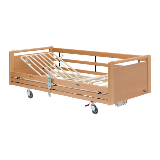
- Page 1 Invacare® SB® 400 en Bed Service Manual DEALER: Keep this manual. The procedures in this manual MUST be performed by a qualified technician.
- Page 2 All rights reserved. Republication, duplication or modification in whole or in part is prohibited without prior written permission from Invacare. Trademarks are identified by ™and ®. All trademarks are owned by or licensed to Invacare Corporation or its subsidiaries unless otherwise noted.
-
Page 3: Table Of Contents
Contents 1 General ........1.1 Introduction . -
Page 4: General
For pre-sale and user information, please see the user This product complies with Directive 93/42/EEC manual. The user manual can be found on Invacare’s website. concerning medical devices. The launch date of this product is stated in the CE declaration of conformity. -
Page 5: Safety
Safety 2 Safety • • Iin — Current in kg — kilogram • • Uin — Voltage in Max — maximum • • Int. — Intermittency min — minutes • • AC — Alternating Current A — Ampere 2.1 General warning All symbols in this table might not be applicable for your WARNING! product. -
Page 6: Assembly
Invacare® SB® 400 3 Assembly All accessories (bed ends, side rails, lifting pole etc) have to dismounted before disassambly of bed, 3.1 Receiving the bed IMPORTANT! Risk of injury while lifting heavy bed parts When you receive the bed, check the packaging. If the packaging –... -
Page 7: Assembly Of Mattress Support (1 Person)
Assembly Both persons: Stand one person on each side and hold both sections. Fit the inserts into the tubes and press the sections together. Make sure the inserts are pushed all the way in (no Both persons: Grab the sides of the lower half of the mattress gap on the frame). -
Page 8: Disassembly Of Mattress Support (2 Persons)
Invacare® SB® 400 Move over to the upper half of the mattress support. Person one = in the head end of the bed. Person two = in the foot end of the bed. Lock the brakes. Insert the plug from the hi/lo motor in the control box and connect the bed to the mains. -
Page 9: Disassembly Of Mattress Support (One Person)
Assembly Loosen the wires. Loosen and remove the finger screws in the middle of the mattress support. Stand at the end of the upper half of the mattress support, hold the sides on the frame and pull it straight out until it comes to a stop. -
Page 10: Disassembly Of Shear Arms
Invacare® SB® 400 Lift the shear arms in both ends, onto the base frame. • The person in the head end of the bed fits the square plastic guides into the guideways. Attach the hi/lo motor to the frame with the cotter pin. Make sure the clamp is closing properly. -
Page 11: Bed Ends
Assembly 3.4 Bed ends Start at the bed foot end. CAUTION! Risk of squeezing If the bed end is not correctly locked it can fall down and cause injury to user. – Make sure the locking pins are engaged. Risks when using bed end with removable plate. –... -
Page 12: Side Rails
Invacare® SB® 400 3.5 Side Rails Mounting Lift the upper bar in one end of the side rail. The release buttons 3.5.1 Scala 2 side rail C must face up/outwards. Press in the locking pin A in the end of the side rail. -
Page 13: Mattress Retainers
Assembly Leg- and hi/lo motor Head end Crosswise laths: Place the mattress retainers A between lath 3 and 4. Lead both wires between the upper frame crossbar and the Lenghtwise laths: Place the mattress retainers between the small shear arms crossbar. brackets C on the outer laths. -
Page 14: Accumulator Backup
Invacare® SB® 400 Mounting the backup battery Install the box, on the bed´s base frame, next to the control unit B. Connect the cable to the control unit. Charging the batteries Connect the control unit to the mains. • The control unit must be connected to the mains for 24 hours prior to first use. -
Page 15: Maintenance
4.1 Maintenance 4.2 Inspection after relocation - Prepare for new user A service contract can be made in the countries, where Invacare® has its own sales company. In certain countries Invacare®offers courses IMPORTANT! in service and maintenance of the bed. Spare parts lists and additional When the bed has been relocated;... -
Page 16: Cleaning And Disinfection
Invacare® SB® 400 4.4 Cleaning and disinfection Electrical components Method: Wipe off with a wet cloth or soft brush. IMPORTANT! Max temp: 40 °C Wrong fluids or methods can harm or damage you product. Solvent/ Water – Follow instructions carefully for either Non-washable chemicals: or Washable components. -
Page 17: Troubleshooting
Troubleshooting 5 Troubleshooting 5.1 Troubleshooting electrical system Symptom Possible cause Remedy Mains are not connected Connect mains Mains indicator does not light up Fuse in the control unit is blown Replace the control unit Control unit is defective Replace the control unit Motor plug is not fully inserted into the Insert the motor plug properly into the control unit. -
Page 18: Technical Data
= release button Line standard l = 206 cm Full length aluminium Invacare® reserves the right to change the stated measurements and h = 40 cm m= on bed end guideways angles without warning. r = centered on side rail... -
Page 19: Electrical System
Technical data Be aware that when a bed has been stored under low Sound level 48 dB (A) temperatures, it must be adjusted to operating conditions Degree of The control unit, external power supply, motors and before use. protection hand controls are protected according to IPx4 or IPx6 (depending on configuration). - Page 20 Invacare® SB® 400 < 5% U (>95% dip in U < 5% U (>95% dip in U Mains power quality should be that of a typical for 0,5 cycle for 0,5 cycle Voltage dips, short commercial or hospital environment. If the user of the...
- Page 21 Technical data Portable and mobile RF communications equipment should be used no closer to any part of the medical bed including cables, than the recommended separation distance calculated from the equation applicable to the frequency of the transmitter. Recommended separation distance: Conducted RF IEC 61000-4-6 Radiated RF...
- Page 22 Invacare® SB® 400 These guidelines may not apply in all situations. Electromagnetic propagation is affected by absorption and reflection from structures, objects and people. 1581143-A...
- Page 23 Notes...
- Page 24 Invacare Sales Companies Ireland: United Kingdom: Invacare Ireland Ltd, Invacare Limited Unit 5 Seatown Business Campus Pencoed Technology Park, Pencoed Seatown Road, Swords, County Bridgend CF35 5AQ Dublin Tel: (44) (0) 1656 776 222 Tel : (353) 1 810 7084...