Table of Contents
Advertisement
Quick Links
Advertisement
Table of Contents

Related Manuals for AOR AR5000A


Summary of Contents for AOR AR5000A
- Page 1 ® AR5000A The New Horizon wide band all mode receiver Operating manual...
-
Page 2: Table Of Contents
Contents 6-18 CONFIG - EXTERNAL I.F. output (SDU5000) ..... 29 6-19 CONFIG - Computer control BPS ........29 (1) Table of contents ................1 6-20 CONFIG - Advanced aerial switching ........30 (2) Introduction ................... 2 6-21 CONFIG - Frequency standard ..........32 2-1 Key information and common menus ........ -
Page 3: Introduction
(2) Introduction (13) Frequency Pass ................58 13-1 Register PASS Frequency ..........59 Thank you for purchasing the AOR AR5000 wide band all 13-2 Manually adding a PASS frequency ........59 mode receiver. The AR5000 uses the very latest NCO 13-3 Editing pass frequencies ........... -
Page 4: Key Information And Common Menus
2-1 Key information and common menus Config menu (6-16, 6-17, 6-18, 6-19, 6-20, 6-21): Press The five VFOs are assigned special status (6-2): LAMP ON VFO-A (VA Manual search between VFO-A BEEP 4 and VFO-B EXT-IF OFF VFO-B (VB Manual search between VFO-A BPS 9600 and VFO-B ANT 1... -
Page 5: Accessories Supplied
Clock programming (14-2): receiver. This inclusion will greatly simplify both frequency entry and search programming. Press then press and hold the key for more The receiver will automatically select the appropriate mode than one second. and channel step. Of course, should you wish then both SELECT 24H / SELECT 12H the mode and channel step may be manually changed as 6-25-00 1 / AM.6-25-00 1... -
Page 6: Looking After Your Receiver
Active short wave desktop loop aerials Designed for the short wave bands (such as the AOR LA320), loop aerials have the advantage of small size when compared to long wire aerials, and being within easy reach of the operator it can be rotated to provide directivity. -
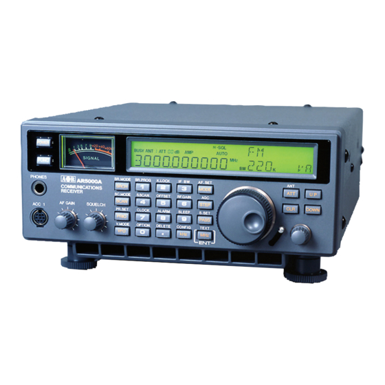
Page 7: Controls And Functions
(5) Controls and functions 5-3 Liquid Crystal Display (LCD) The AR5000 receiver is housed in a strong metal cabinet. Controls for operation are located on the front of the Display of operational information is provided via a high cabinet with connections to the rear. contrast wide angle backlit green LCD, this includes Front panel frequency, mode, bandwidth, alpha-numeric comments... - Page 8 The display is split into 28 specific areas, a summary of which follows: hold for more than one second. A sleep selection menu will be displayed, use the MAIN DIAL or SUB DIAL to 1 “BUSY” legend appears when the squelch is open select the required time (between 1 &...
-
Page 9: Main (Large) Rotary Tuning Control - Main Dial
SR” In search mode only a bank number and the legend “SR the MHz / kHz LCD legends. The available selection of is displayed - but no channel number. AGC is: OFF, FAST, MIDDLE & SLOW. 17 The one or two digit number indicates which scan or 25 I.F. -
Page 10: Removable Feet
Note: A microprocessor reset switch is hidden behind clockwise until the background noise just disappears the upper section of the lever’s slot. Reset can be useful (threshold), this is the most sensitive setting of the control. if the receivers operation has been upset due to static In practice the control is usually rotated a little further discharge or power supply transients. -
Page 11: Volume Control (Af Gain)
5-10 Volume control (AF GAIN) 4 & 5 Tape record motor switching using a non-polarised photo-MOS relay. The switched output is designed for The volume control is located to the left of the front panel low voltage (12V) d.c. with a maximum current of 350mA, underneath the signal meter. - Page 12 - SR.MODE If the sequence is keyed, additional parameters affecting VFO search operation may be Pressing the key places the receiver into program configured: DELAY, L-SQ & VOICE. search mode. There are twenty search banks in total numbered from 00 to 19. To change the bank number - SR.PROG rotate the SUB DIAL, the bank number appears in the top right of the LCD.
- Page 13 - OFFSET - ALARM Figure FIVE for the numeric input of frequencies, bank, Figure EIGHT for the numeric input of frequencies, bank, channel numbers etc. channel numbers etc. The sequence initiates FREQUENCY The sequence activates the ALARM which OFFSET where the receiver will automatically jump to a can be programmed to switch the receiver on automatically pre-programmed frequency offset, this is very useful for as an alarm clock or for unattended recording with the...
- Page 14 - CONFIG In addition unusual step sizes may be entered using the numeric keypad (i.e. for 22 kHz or This key is used to accept frequency input via the numeric for 200 Hz). keypad in kHz format. For example: To key in a frequency of 954 kHz key the LCD will display The SUB DIAL may also be configured for: MAIN (same as...
- Page 15 may also be controlled via the optional AS5000 switching key also allows selection On/Off of certain unit. AUTO may be selected where the aerial will be options while in menus (such as step-adjust) and selects automatically switched based upon the programming of defaults in other menus.
-
Page 16: Rear Panel
If held for more than one second while in VFO mode, a more than two aerials (up to four) may be connected to frequency search is initiated. If held for more than one the receiver and switched manually or automatically from second while in memory recall mode, the scan process the receivers front panel. -
Page 17: Ext Sp - External Speaker Output Socket
2 Locate and cut the yellow jumper wire positioned above This BNC socket provides a suitable output to drive the the MUTE terminal. optional AOR SDU5000 spectrum display unit providing 3 Refit the upper case. a usable ± 5 MHz of bandwidth. The output to this socket... -
Page 18: Ant 2
5-21 ANT 2 the last right hand digit of the frequency readout (Hz position) to ensure the receiver is in AUTO MODE. This This is the secondary aerial (antenna) input for the AR5000 places the receiver into a known state of operation ready receiver. -
Page 19: Tuning The Receiver Using The Rotary Controls
VFO-E Accept the frequency from the scan mode key for more than one second, the “AUTO” legend will appear on the LCD to confirm selection. If a frequency is keyed in to VFO-E and the held for more than one second the search process will 6-4 Entering a frequency via the numeric keypad commence from the displayed frequency. -
Page 20: Correction Of Frequency Input Via The Numeric Keypad
Providing the AUTOMODE facility has been engaged Most known step sizes are available with the exceptions (so that the “AUTO” legend is displayed above the right such as TV channels which are allocated with 6MHz or hand digit of frequency readout), you may monitor the 4MHz spacing. -
Page 21: Step-Adjust
Note: The MAIN DIAL is a mechanical encoder and as Step-adjust is used when the receiving frequency is not such small variations in tuning may be experienced or the divisible by the step size in use (It is possible that step- frequency may move slightly after rotation, this is normal. - Page 22 Select receive bandwidth: For point-to-point Note: You may review the step-adjust value quite simply... communications a bandwidth of 15 kHz usually provides While in VFO mode, press followed by best results, however if adjacent channel interference is access the step-adjust sub menu. In the above example experienced a bandwidth of 6 kHz may provide better the step-adjust value will be 2.0 kHz, refer to the following t o access the I.F.
-
Page 23: Frequency Offset
LCD inviting you to enter the value for step-adjust (2 kHz 2. While the “FR-OFS” legend is flashing on the display to indicate that the frequency offset menu has been in the example). Press selected, rotate the SUB DIAL to select a new (blank) location (i.e. - Page 24 The SUB DIAL is used to change mode. When you have used on any frequency within the set’s range. made your selection, press to accept the new In normal operation AUTOMODE should be used. The mode. The display will revert to VFO mode and the legend “AUTO”...
-
Page 25: If Bandwidth
In FM mode the options are AGC ON / OFF and in other modes are OFF, FAST, MIDDLE and SLOW. When AGC Lower Side Band - is a form of Single Side Band (SSB). OFF has been selected, two horizontal bars “=“ are LSB tends not to be used commercially but is extensively displayed on the LCD between the kHz and MHz legends. -
Page 26: Af Set - (Audio Characteristics)
Manually selecting I.F. bandwidth. 1 Audio Low Pass Filter The audio low pass filter is useful to cut off high tones The sequence activates the I.F. bandwidth (allowing low tones to pass) to improve intelligibility of weak menu. signals in close proximity to adjacent interference and to remove hiss making listening for extended periods easier on the ears. - Page 27 The audio high pass filter selection is accessed via a 4 CW Pitch sub menu. Comfortable listening to CW (Continuous Wave, often A-LPF 3.0 kHz referred to as Morse code) is usually centred around a A-HPF 0.05 A-HPF 0.05 A-HPF 0.05 A-HPF 0.05 A-HPF 0.05 kHz <<<...
-
Page 28: Audio Tone Eliminator (T-Elmt)
3. Press to accept the changes, to abort Unwanted tone Suggested setting to move on to the audio internal / external selection. 0.4 (kHz) 0 ~ 31 50 ~ 81 6-12 Audio tone eliminator (T-ELMT) 88 ~ 113 Various utility radio users are permitted to transmit their 136 ~ 155 signals with an accompanying continuous tone (pilot tone) which is over ridden by the operator’s audio (voice). -
Page 29: Dtmf Decoder
6-13 DTMF decoder 6-14 RF Attenuator & preamplifier DTMF (Dual Tone Multi Frequency) tones are used by The AR5000 features an RF stepped attenuator and 00 dB” and “AMP” are many VHF/UHF communications services and amateur preamplifier. LCD legends “ATT 00 radio operators to control switching devices and to enable used to display the settings in use. -
Page 30: Config - Lamp
The CONFIG menu provides access to: lamp, keypad 6-18 CONFIG - EXTERNAL I.F. output beep tone, external IF output, remote RS232 baud rate, (SDU5000) aerial automatic switching and internal / external frequency reference. The AR5000 is capable of providing a 10.7 MHz I.F. output suitably wide enough to drive the optional SDU5000 spectrum display unit with a bandwidth of up to ±... -
Page 31: Config - Advanced Aerial Switching
onto paper (see later in this section 6-20) to form a clear Use the keys to scroll through the menu picture of what is required. Each aerial may be until the REMOTE BPS menu is displayed. programmed for 10 separate frequency ranges (each LAMP ON being referred to as a channel, ANT 1 channel 0 ~ 9, BEEP 4... - Page 32 Entering simple aerial switching data In this example all four aerials have been used as if the optional AS5000 were in use, complex programming is In this example aerial 2 (“ANT 2 2 2 2 2 ”) will be programmed for still possible using the standard two aerial inputs “ANT 1 1 1 1 1 ”...
-
Page 33: Config - Frequency Standard
7 Rotate the MAIN DIAL to select “ANT 4 4 4 4 4 ”. Delete any 6-21 CONFIG - Frequency standard data already programmed using the key until the The AR5000 is fitted with a 12.8 MHz internal TCXO legend “- - - - - - - - - -” is displayed. (Temperature Compensated Crystal Oscillator) as standard to ensure the ultimate in frequency precision. -
Page 34: Memory Banks & Channels
(7) Memory banks & channels Note: When the receiver is switched OFF using the front panel key, all VFO data will be automatically stored It is very convenient to store commonly used frequencies into EEPROM memory storage. However, should the into a memory bank along with mode and attenuator power be removed while the receiver is switched on (power status, this saves having to key the data in over and over... -
Page 35: Memory Recall - Recalling Receive Data From Memory
bank, select scan channel, pass frequency etc). The “< - -” legend then reverses to point back to 1 = Display a blank “ ”, cancel whatever where the frequency was displayed. If the legend letter is currently displayed “- - - - - - - - - -” is displayed then the current memory 2 = Start at number “1 1 1 1 1 ”... -
Page 36: Transfer Of Memory Channel To Vfo
If the desired memory channel is not immediately displayed For example, let’s assume that you wish to store a new it may be RECALLED by keying in the required location. frequency of 92.7 MHz into memory bank “1 1 1 1 1 ” location “00 00”... -
Page 37: Deleting Memory Channels And Banks
Once a channel has been recalled, to delete data from Press to over-write memory location 123. The memory channel “123 123” press . The legend TXT” legend will be displayed inviting you to select new “TXT MEM-CH MEM-CH” is displayed on the left of the LCD MEM-CH “DEL MEM-CH... -
Page 38: Scan - Scanning Memory Channels & Banks
(8) SCAN - scanning memory channels AUTO-STORE reserves memory bank “0 0 0 0 0 ” so that active & banks frequencies found while conducting a SEARCH may be automatically written to memory (see SEARCH at section The AR5000 has a SCAN MODE whereby the contents 12 with auto-store at section 12-19). -
Page 39: Scanning A Memory Bank
Limitations of SCAN mode Finally when the channel becomes clear again (the signal disappears and squelch closes), the receiver will wait for Should a number of different modes and wide range of an additional two seconds (initial default) to allow for a frequencies be used, then the SCAN process may be reply on the channel before resuming the scanning affected by noise or differences in squelch characteristic... -
Page 40: Memory Bank Linking To Scan All Memory Banks
8-5 Memory bank linking to scan ALL Deselecting linked banks memory banks It is not necessary to deselect bank link identifiers if you wish to scan a single scan bank, simply access the bank When shipped from the factory using default settings all link menu and use the key to switch the bank link memory banks are UNLINKED so may only be scanned... -
Page 41: Scan Channel Pass (Lockout)
Alternatively you could switch bank link OFF or select a Pressing when in memory recall mode toggles bank link profile where group programming has not been the status of the displayed memory channel scan pass selected. (lockout)... To return to the GROUP selection, rotate the SUB DIAL until “PASS”... -
Page 42: Cyber Scan In Scan Mode
To access the additional facilities of BANK LINK / SETUP . Initially the BANK LINK menu is press displayed, the keys allow selection of the additional facilities operating as a carousel. The MAIN DIAL and SUB DIAL may be rotated to change 8-9 Cyber Scan in SCAN mode values on each menu. -
Page 43: Scan - Delay
is used to select OFF, use of the MAIN DIAL 9-2 SCAN - DELAY If the and SUB DIAL afterwards will result in the value continuing The scan DELAY parameter affects the time the AR5000 from whatever was last selected, this speeds up the will remain on an active channel in scan mode once the selection process. -
Page 44: Scan - Mode (Receive Mode Am, Fm Etc)
selection process. In fact the key may be used as To accept the changes to MODE scan press a toggle between OFF and the new setting. return to normal display (SCAN, SEARCH or VFO mode). Alternatively you may move to previous options using the keys. -
Page 45: Select Scan - While In Scan Mode
to be tagged or un-tagged, the SUB DIAL is used to change 10-2 SELECT SCAN - while in SCAN bank number. mode (tagging and un-tagging) When the memory channel has been tagged using the While the receiver is scanning, the AR5000 will stop on , the legend “S S S S S ”... -
Page 46: Priority Operation
The right of the LCD will display the legend “* *” if select scan channels exist and “- -” if there are none to delete. Once priority has been activated, the contents of the delete select scan channels memory channel used (default 000) may be altered without affecting the data used for PRIORITY operation which is (un-tag them all) press , the legend will change to... -
Page 47: Search
P-INTER P-INTER P-INTER P-INTER When the interval menu is selected the legend “P-INTER Pressing for more than 1 second will initiate the 05” is displayed (with 05 being the default of 5 seconds). process of storing the frequency into a memory channel. Limitations of SEARCH mode SEARCH mode is extremely effective for AM &... -
Page 48: Simple Search (Vc, Vd, Ve)
Cancelling manual search Manual search may be cancelled by pressing . The display will either revert to VFO-A or VFO-B depending upon which was being used when manual search was 2 Select VFO-B. Press the , the legend “VB VB” is selected. -
Page 49: Optimising Vfo Search Parameters
Saving busy frequencies into memory It is possible to save interesting frequencies into memory. While stopped on an active frequency press and hold the key for more than one second, the MEMORY VC” or “VD VD” 2 To initiate simple frequency search (while “VC INPUT menu will appear. -
Page 50: Program Search Banks
VFO SEARCH - LEVEL SQUELCH You may find this facility useful for skipping over STRONG signals but WEAKER noisy signals may fool the AR5000 The LEVEL SQUELCH parameter causes the receiver into thinking that modulation is present as will signals which to check the signal strength of active frequencies and to have pilot tones or heterodynes present. -
Page 51: Starting Program Search
An example of possible programming is as follows (in these The key has the effect of a TEN key, i.e. bank 13 examples the mode, step etc are taken from the may also be selected as in a similar way to the AUTOMODE bandplan data): action of some TV &... -
Page 52: Programming And Reprogramming Search Banks
12-7 Programming and reprogramming PROGRAM SEARCH BANKS You may wish to specify your own frequency limits or modes for program search banks. There are 20 program 05” and initiate the To accept the bank location of “05 search banks in total 00, 01, 02, 03, 04, 05, 06, 07, 08, programming process press 09, 10, 11, 12, 13, 14, 15, 16, 17, 18 &... - Page 53 MODE FM MODE FM <<< <<< MODE FM MODE FM MODE FM <<< <<< <<< MODE FM IFBW 0.5 (skipped if AUTOMODE is used) IFBW 15.0 STEP 1.000 (skipped if AUTOMODE is used) STEP 25.000 <<< <<< <<< <<< <<< To aid text entry, a decimal “.”...
-
Page 54: Deleting Program Search Banks
search bank is desired then override the current aerial 12-9 SEARCH - outline introduction to selection by pressing additional facilities available select automatic aerial switching... of course ANT 1, ANT 2, ANT 3 or ANT 4 may be selected using this menu During program search, the AR5000 tunes to every , use the SUB DIAL instead). -
Page 55: Linking Program Search Banks
12-10 Linking program search banks = search bank 11 = search bank 12 When shipped from the factory (using default settings) all = search bank 13 program search banks are UNLINKED so may only be = search bank 14 searched on an individual basis by selecting the search = search bank 15 bank identifier by rotating the SUB DIAL or keying in the two = search bank 16... -
Page 56: Linking Only A Few Search Banks
To return to the GROUP selection, rotate the SUB DIAL until 12-11 Linking only a few search banks one of the desired search bank numbers is displayed. When the BANK LINK menu has been selected “ON ON” (as per section 12-10 of this manual), ALL search banks are 12-13 Additional PROGRAM SEARCH linked. -
Page 57: Program Search - Delay
PAUSE saves you having to manually intervene to force the search process to resume or the need to lockout frequencies using the FREQUENCY PASS facility. The limits are OFF and 01 to 60 seconds (default OFF). To accept the changes to DELAY, press to return Press to access the BANK LINK menu. -
Page 58: Program Search - Voice
specific requirements... the lower level settings may not be usable when high noise is present. 12-17 PROGRAM SEARCH - VOICE 12-18 Cyber Search The search VOICE parameter determines the way in which an active frequency is determined by sampling the audio A special facility has been provided to speed up the search modulation. -
Page 59: Auto-Store
PAUSE OFF 12-19 AUTO-STORE DELAY 2.0 The auto-store (A.STORE) facility enables the first 100 L-SQ OFF VOICE OFF busy frequencies located during search to be automatically saved in memory bank “0 0 0 0 0 ” for later review and scanning. A.STORE OFF A.STORE OFF A.STORE OFF... -
Page 60: Register Pass Frequency
Frequencies which have been registered as a pass Press the key to enter add/edit/delete mode. The frequency will not be received during a subsequent search. selected bank number will be displayed under the legend “BANK”, if in VFO mode the bank number will be replaced All search banks are independent from each other. -
Page 61: Editing Pass Frequencies
00” being displayed under the Notes: You can enter a PASS frequency down to the displayed with the legend “00 100kHz order only (as a PASS frequency is valid within a bank number. range of ± 10kHz). The PASS frequency can be entered anywhere within The AR5000’s receive range but it must be noted that the search rate will slow down if the pass frequency is entered outside of the selected program... -
Page 62: Deleting Complete Banks Of Pass Frequencies
search bank does not contain any frequency pass channels. Press the key to enter add/edit/delete mode. The selected bank number will be displayed under the legend “BANK”, if in VFO mode the bank number will be replaced by the letter “V V V V V ”. Rotate the SUB DIAL to review the pass channels. -
Page 63: Setting Time
SELECT 24H / SELECT 12H 14-2 Setting time 6-23-16 1 / AM.6-23-16 1 <<< <<< Clock 1 and clock 2 may display different hours and text <<< <<< <<< 4-23-30 2 / PM.4-23-30 2 but the minutes and seconds will be common to both TXT 2 clocks. -
Page 64: Alarm Clock
SELECT 24H / SELECT 12H Alarm BEEP 6-25-00 6-25-00 6-25-00 6-25-00 6-25-00 / AM.6-25-00 / AM.6-25-00 / AM.6-25-00 / AM.6-25-00 / AM.6-25-00 <<< <<< <<< <<< <<< During ALARM BEEP mode, the AR5000 will power-up TXT 1 at the pre-set time causing the beep sounder to activate 4-23-30 2 / PM.4-23-30 2 (repeated three beeps) at the pre-set volume level. -
Page 65: Alarm Activation
Rotate the MAIN DIAL or SUB DIAL to select how long Note: An audible low level noise may be heard while rotating the SUB DIAL in this menu with a click while passing (in minutes) the ALARM or RADIO will stay powered-on once the alarm has activated. -
Page 66: Option - Descrambler (Voice Inverter) - Ds8000
(such as some cordless phones). Such a board 1 Press the key then press and hold the is not produced by AOR but the receiver has been for more than one second. designed to accept the DS8000 - available from dealers in some countries. -
Page 67: Descrambler Operation
Assuming that power is connected to the AR5000 and To increase versatility different CTCSS tones may be programmed into each memory and VFO. the power switch is currently OFF, press and hold key then power up the receiver by pressing and releasing the switch while still holding the key. -
Page 68: Installation Of The Ct5000
16-1 Installation of the CT5000 key then power up the receiver by pressing and releasing the switch while still holding the Only the upper case of the AR5000 needs to be removed CTCSS CTCSS key. Now release the key. The “CTCSS CTCSS CTCSS”... -
Page 69: Ctcss Squelch
Note: When the CTCSS search is active it is not possible (17) Optional I.F. filters (500 Hz, 2.5 kHz to toggle the frequency display and text display. If the & 5.5 kHz) optional CT5000 board is not fitted the above procedure will result in no audio being produced. -
Page 70: Installation Of Other Filters
3 Pull the PCB towards the front panel and lift it as shown 17-2 Installation of other filters in the diagram. Consult your AOR dealer if you wish to install other filters such as 2.5 kHz and 5.5 kHz. To add these substitute filters, the standard ceramic filters must be replaced, this requires good quality tools and technical skill. -
Page 71: Trouble Shooting - Microprocessor Reset
The reset switch is located at reset the top of the slot about 10mm behind the front panel. Should the AR5000 fail to operate correctly, refer to the following instructions before contacting your AOR dealer for support. Memory / search bank corruption 18-1, 18-2, 18-3... -
Page 72: Af.set Int/Ext
18-5 What next - dealer support position extinguishes. Not used on current unit. If any apparent fault symptom repeatedly occurs contact your AOR dealer for advice, have the serial number and Power-On date of purchase to hand. Ensure that you can provide a detailed description of the fault condition. -
Page 73: Optional Accessories
DS8000 speech inverter Compact aerial designed for installation where space is a problem. The WA7000 is active on Speech inverter board (non AOR product). the lower frequency band 30kHz to Not available in all countries. 30MHz and passive on the higher band between 30MHz to 2000MHz. - Page 74 at VHF/UHF frequencies than for short wave. If possible It is quite easy to make a dipole for short wave, for that the aerial should have a clear path to the horizon. Results matter one can be easily made up for VHF or UHF too. If are usually disappointing when an installation is in a loft being made for VHF-UHF, the centre connection of the space.
- Page 75 Short wave desktop loop aerials have the advantage of called the ABF125. This will help minimise the possible small size (such as the AOR LA320). They too have tuning effects of breakthrough when listening to VHF airband in controls to reject unwanted signals. As the loop is within...
-
Page 76: Propagation - Short Wave Bands
(21) Propagation - short wave bands If the transmitted frequency is too high to be reflected by the ionosphere, VHF and UHF transmissions generally only propagate or the angle too steep, transmissions will simply pass relatively short distances when compared to short wave straight though the ionosphere without being reflected and signals. -
Page 77: Specification
transmissions will pass straight into space. MINimum Aerial input 50 OHM unbalanced. N-TYPE usable frequency is also stated for similar reasons. & SO239 Many propagation predictions and statistics are published Audio output (13.5V) 1.7 WATT into 8 OHMS and usually available from most country’s National @ 10% THD Amateur Radio and short wave listeners representatives. - Page 78 AR5000 OPERATING MANUAL PAGE 77...
- Page 79 AR5000+3 English language operating manual addendum V1.3 20/10/99 ©AOR LTD, 1997, 1998, 1999 E&OE - Page 1...
- Page 80 AOR USA, INC. 20655 S. Western Avenue, Suite # 112 Torrance, CA. 90501, USA Tel: (310) 787 8615 Fax: (310) 787 8619 info@aorusa.com www.aorusa.com AR5000+3 English language operating manual addendum V1.3 20/10/99 ©AOR LTD, 1997, 1998, 1999 E&OE - Page 2...
- Page 81 AOR Ltd ® 2-6-4 Misuji, Taito-ku, Tokyo 111, Japan. Tel: +81 3 3865 1681 Fax: +81 3 3865 1697 AOR (UK) Ltd Unit 9 Dimple Road Business Centre, Matlock, Derbys DE4 3JX, England Tel: +44 1629 581222 Fax: +44 1629 580070 e-mail: info@aoruk.com...