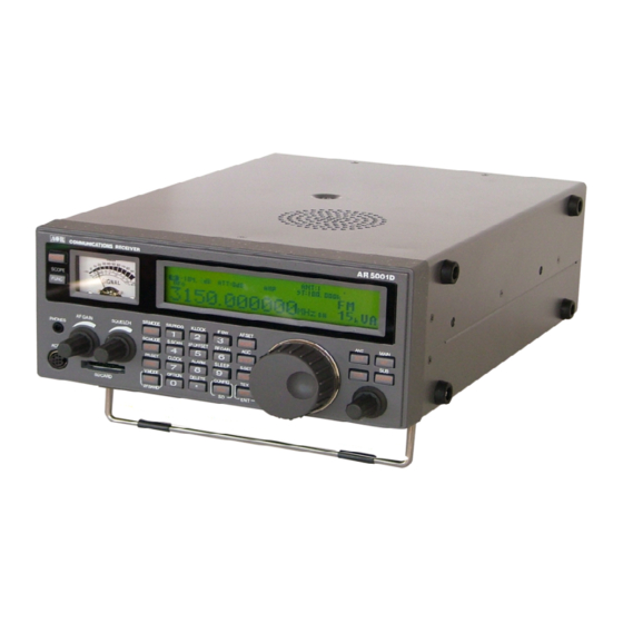
AOR AR5001D Manual
Digital processing communications receiver
Hide thumbs
Also See for AR5001D:
- Operating manual (96 pages) ,
- Manual (52 pages) ,
- Operating manual (95 pages)
Table of Contents
Advertisement
Quick Links
Download this manual
See also:
Operating Manual
Advertisement
Table of Contents

Related Manuals for AOR AR5001D


Summary of Contents for AOR AR5001D
- Page 1 All manuals and user guides at all-guides.com ® AR5001D Digital Processing Communications Receiver PC Command List AOR, LTD. Aug.30, 2010...
- Page 2 All manuals and user guides at all-guides.com...
-
Page 3: Table Of Contents
AUX 1............................. 5 SYSTEM REQUIREMENTS ......................6 1-3-1 USB DRIVER INSTALLATION....................6 CONTROL COMMANDS ........................9 COMMAND FORMAT........................9 RESPONSE FORMAT......................... 10 POWER ON/OFF THE AR5001D ....................10 2-3-1 WAKE UP..........................10 2-3-2 STANDBY MODE........................10 2-3-3 SLEEP TIMER ........................10 2-3-4 END REMOTE CONTROL .................... - Page 4 All manuals and user guides at all-guides.com 2-9-1 LEVEL SQUELCH (RQ COMMAND) ................... 17 2-9-2 LEVEL SQUELCH (HQ COMMAND) ................... 17 2-9-3 VOICE SQUELCH ........................ 18 2-9-4 NOISE SQUELCH (NQ COMMAND) ................... 18 2-9-5 NOISE SQUELCH (QN COMMAND) ................... 18 2-9-6 NOISE SQUELCH ON/OFF ....................
- Page 5 All manuals and user guides at all-guides.com 3-6-6 DELETE MEMORY BANK ....................31 SCAN ............................31 3-7-1 START SCAN........................31 3-7-2 SCAN GROUP SETTING ..................... 31 3-7-3 MEMORY BANK LINK ON/OFF ................... 32 3-7-4 MEMORY BANK LINK ......................33 3-7-5 MODE SCAN ........................
- Page 6 PLAYBACK ..........................43 OPERATION STATUS ......................... 44 SEND MEMORY DATA TO SD CARD..................44 7-10 SEND SD MEMORY FILE TO AR5001D................... 44 7-11 RENAME SD FILE NAMES ....................... 45 DATA EDITOR ............................ 46 CONFIGURATION SETTINGS OF OTHER PARAMETERS ............46 SELECTING INTERFACE ......................
-
Page 7: Pc Control
All functions of the AR5001D can be controlled by a PC. 1-1-1 USB DRIVER Before connecting the AR5001D to a PC, the USB driver for the AR5001D needs to be installed. The USB driver can be downloaded from the manufacturer’s website. (Shown Below) http://www.ftdichip.com/ftdrivers.htm Click “VCP Drivers”, then select the device name “FT232B”. -
Page 8: System Requirements
All manuals and user guides at all-guides.com With an optional LAN interface unit, the AR5001D can be controlled via the internet. All the control commands for the LAN interface are the same as the USB control commands. SYSTEM REQUIREMENTS Hardware: PC with 2GHz Dual Core CPU with 1GB RAM USB Port (USB 2.0) - Page 9 All manuals and user guides at all-guides.com 9. Check “No, not this time” and click “Next”. 10. Check “Install from a list or specific location [Advanced]” and click “Next”.
- Page 10 All manuals and user guides at all-guides.com 11. Check “Search for the best driver in these locations.”, “Include this location in the search:”. Select the folder where the driver data you downloaded is located. 12. Click “Next”.
-
Page 11: Control Commands
All manuals and user guides at all-guides.com 13. When the installation is completed, click “Finish”. 14. In order to find the assigned serial port for the USB port, click the “Start”, “Control Panel”, “System”, “Hardware”, “Device Manager”, “Ports (COM&LPT)” on the PC monitor screen.. USB Serial port (COM x) will be indicated. -
Page 12: Response Format
Although there is no local echo, a specified response should come back from the AR5001D after confirming the correct command. If an invalid command is sent to the AR5001D, ? <CR><LF> (0x3f, 0x0d, 0x0a) will be returned as an unrecognized command. -
Page 13: Frequency/Channel Up/Down
All manuals and user guides at all-guides.com To read: ST<CR> Response: STnnnnnn FREQUENCY/CHANNEL UP/DOWN ^(1EH) Frequency / memory channel up v (1FH) Down Frequency/memory channel down RECEIVE MODES, IF BANDWIDTH, AUTO MODE, DESTINATION 2-7-1 RECEIVE MODES (Note: Some functions below 25MHz may not be available due to its configuration.) Command Description Mode... -
Page 14: If Bandwidth
All manuals and user guides at all-guides.com To read: MD<CR> Response: MDnn 2-7-2 IF BANDWIDTH (n: 0 ~ 9) (default: 7) 0: 200 Hz 1: 500 Hz 2: 1 kHz 3: 3 kHz 4: 6 kHz 5: 15 kHz 6: 30 kHz 7: 100 kHz 8: 200 kHz 9: 300 kHz... -
Page 15: Decode Assist Functions
All manuals and user guides at all-guides.com DECODE ASSIST FUNCTIONS 2-8-1 AUTO NOTCH (NOTCH) (n: 0 ~ 3) (default: 0) 0: Off 1: Low 2: Medium 3: High To read: LS<CR> Response: LSn 2-8-2 NOISE REDUCTION (NR) (n: 0 ~ 3) (default: 0) 0: Off 1: Low... -
Page 16: If Shift
All manuals and user guides at all-guides.com 127: 700 (7000Hz) To read: SC<CR> Response: SCnnn 2-8-5 IF SHIFT Not available in FM mode. ISxnnn X: +, - (shift direction) (n: -120 ~ +120) (default: +000) (-1200Hz ~ +1200Hz) Incremental 5 (50Hz) +000: Off To read: IS<CR>... -
Page 17: Tone Squelch (Ctcss)
Response:CNnn Note: When a CTCSS tone is detected, its frequency will be displayed. If the decoded tone frequency matches the set frequency, the AR5001D will display its frequency followed by an asterisk (*). (Example) CN15 103.5* The set CTCSS frequency matches the decoded tone frequency. -
Page 18: Dtmf Code
DCS codes To read: DC<CR> Response:DCnnn Note:When the AR5001D is detecting a DCS code, it will be displayed. If the decoded code matchess the set code, the AR5001D will display its code followed by an asterisk (*). (Example) DS131 131* The set DCS code matches the decoded DCS code. -
Page 19: High Pass Filter
All manuals and user guides at all-guides.com To read: LP<CR> Response: LPn 2-8-14 HIGH PASS FILTER (n: 0 ~ 2) (default: 0) 0: Thru 1: 300Hz 2: 600Hz To read: LP<CR> Response: LPn SQUELCH 2-9-1 LEVEL SQUELCH (RQ COMMAND) The RQ command is used to automatically set squelch level according to the receive frequency. (i.e. -
Page 20: Voice Squelch
All manuals and user guides at all-guides.com 2-9-3 VOICE SQUELCH (n: 0, 1) 0: Off, 1: On (default: 0) VTnnn nnn:000 ~ 255 Delay time (default: 008) nn: 0 ~ 7 Squelch level (default: 3) To read: VQ<CR> or VT<CR> or VL<CR> Response: VTnnn or VVn 2-9-4... -
Page 21: Antenna Select
All manuals and user guides at all-guides.com Response: ATyn y : 0, 1 0: Auto attenuator Off 1: Auto attenuator Onf n : 0 ~ 3 See above 2-11 ANTENNA SELECT (n: 0 ~ 4) (default: 1) Auto select Antenna 1, Antenna 2 Antenna 3, Antenna 4... -
Page 22: S-Meter
/scan finished one circle. 2-13-2 AUTO SIGNAL LEVEL REPORT LTnnnn (n: 0000 ~ 6000) (default: 0000) (in approximately 10 mS step) 100: One second interval 0000: Off (default) The AR5001D sends s-meter level with above interval. To read: LT<CR> Response: LTnnnn... -
Page 23: Audio Recorder Control
All manuals and user guides at all-guides.com 2-14 AUDIO RECORDER CONTROL 2-14-1 CONTROL RELAY STATUS (n: 0 , 1) 0: Off (Relay contact open) (default) 1: On (relay contact closed) The relay contact is available at the ACC1 connector to control an external audio recorder device. -
Page 24: Receive Commands
All manuals and user guides at all-guides.com RECEIVE COMMANDS VFO MODE (x: A ~ E) RFnnnnnnnnnn nnnnnnnnnn (Hz) (default:0088.000000) (MHz) The Vx command is to select VFO A ~ VFO E. To set the frequency, use the RF command after selecting the VFO. To set the frequency in MHz, use a (.) (decimal). -
Page 25: Vfo Mode Noise Squelch (Db Command)
All manuals and user guides at all-guides.com VFO MODE NOISE SQUELCH (DB COMMAND) The DB command is used in VFO mode to automatically set noise squelch level according to the receive frequency. (i.e. if the receive frequency is below 25 MHz, then squelch will be set to HF band.) DBnnn (nnn: 000 ~ 255) (default: 000) -
Page 26: Search Bank
All manuals and user guides at all-guides.com Response: DDn.n (0.0 ~ 9.9 seconds) 3-5-3 SEARCH BANK SEnn (nn: 00 ~ 39) Search Bank number SLnnnnnnnnnn (Lower limit Frequency, Hz) SUnnnnnnnnnn (Upper limit Frequency, Hz) STnnnnnn (Search frequency step, Hz) 0 ~ 1000 kHz SHnnnnnn (Search step adjust frequency, Hz) 0 ~ 999.999 kHz (n: 0, 1) 0: Auto mode Off (default: 1) 1: Auto mode On... - Page 27 All manuals and user guides at all-guides.com Format:GSnn<SP>SDnn<SP>SBnnn<SP>SAnnn<SP>SPnn<SP>ASn<SP>BQn<SP>B Kaabbccdd……<CR> Note: Refer to individual command for details of each field To read: GS<CR>, GSnn<CR>, or GS%%<CR> Response: GS<CR> Displays the current search group parameters GSnn<CR> Displays the designated search group parameters (nn: 00 ~ 19) GS%%<CR>...
-
Page 28: Pass Frequency
All manuals and user guides at all-guides.com Response: SA<SP>nnn nnn: 000 ~ 255 Bit 7: Voice squelch on/off (similar to VQ command) Bit 6 ~ 4: Voice squelch level (similar to VV command) Bit 3 ~ 0: Voice squelch delay (upper 4 bit) (similar to VT command) 3-5-3-6 SEARCH MODE NOISE SQUELCH... -
Page 29: Pass Frequency (Ps Command)
In VFO search mode, search mode, or FFT search mode, register the specified frequency to the current search bank. 3-5-6 SEARCH FREQUENCY LIST There are 1024 channels of search memory in the AR5001D. By executing the FL command, 40 channels of data will be displayed. -
Page 30: Copy Search Frequency List To Memory Bank
All manuals and user guides at all-guides.com (n: 0 ~ 4, %) 0: Displays the latest 40 channels (frequencies may duplicate.) 1: Displays the latest 40 channels (frequency not duplicated) 2: Displays 40 channels with the strongest signal (frequency may duplicate). 3: Displays 40 channels with the strongest signal (frequency not duplicated.) 4: Displays most frequently detected signals. -
Page 31: Memory Channel
They must always be used in conjunction with the FF command.) MEMORY CHANNEL The AR5001D features 2,000 memory channels (50 channels in each of the 40 banks). The number of memory banks can be reconfigured between 5 ~ 95 (in 5 incremental). -
Page 32: Memory Channel Setting (Mr Command)
All manuals and user guides at all-guides.com 3-6-2 MEMORY CHANNEL SETTING (MR COMMAND) MXbbcc<SP>RFnnnnnnnnnn<SP>AUn<SP>….. MXbbcc: bb: 00 ~ 39 (Memory bank) cc: 00 ~ 95 (Memory channel) RFnnnnnnnnnn Frequency (Hz) or Frequency with decimal (MHz) (i.e. 123.5 (MHz)) GAn: n: 0, 1 (Memory select, de-select) 0: De-select (default) 1: Select MPn:... -
Page 33: Memory Channel Registration Status
All manuals and user guides at all-guides.com 3-6-4 MEMORY CHANNEL REGISTRATION STATUS MZbb Acquire memory channel registration status. Response: MZbb<SP>nnxxxxxxxxxxxxxxxxxxxxxxxxxx nn: Assigned number of memory channel for the specified bank (default: 50) xx……… : Status of memory channels (00 ~ 99) Converts 2 characters into hexadecimal data from LSB. -
Page 34: Memory Bank Link On/Off
All manuals and user guides at all-guides.com The AR5001D features 20 scan groups. GMnn: nn: 00 ~ 19 (Scan bank number) (default: 00) XDnn: nn: 00 ~ 99 (Squelch delay time) (in 0.1 sec.) (Time before resuming scan after signal dropped) (default: 20) -
Page 35: Memory Bank Link
All manuals and user guides at all-guides.com 3-7-4 MEMORY BANK LINK BMnn<SP>nn<SP>nn<SP>…. (nn: 00 ~ 39, %%) Memory bank number %%: Link clear To read: BM<CR> Response: BM<SP>b<SP>b<SP>b…. (40 banks) ….. Note: When bank is not linked, “b” will be displayed as “-“. 3-7-5 MODE SCAN XMnn... -
Page 36: Scan Mode Delay Time
All manuals and user guides at all-guides.com Response: XA<SP>nnn nnn: 000 ~ 255 Bit 7: Voice squelch on/off (similar to VQ command) Bit 6 ~ 4: Voice squelch level (similar to VV command) Bit 3 ~ 0: Voice squelch delay (upper 4 bit) (similar to VT command) 3-7-8 SCAN MODE DELAY TIME... -
Page 37: Multi Frequency Receive
All manuals and user guides at all-guides.com To read: GA<CR> Response: GAn 3-7-11-3 SELECT SCAN MEMORY CLEAR Clear select scan memory (direct command) 3-7-11-4 READ SELECT MEMORY Read select memory (direct command) To read: GR<CR> Response: GRnnnn<SP>MXnnmm<SP>RFnnnnnnnnnn<SP>TMcccccccccccc MULTI FREQUENCY RECEIVE The Duo frequency / Tri frequency receive functions allow you to monitor two or three separate frequencies simultaneously. -
Page 38: Duo Frequency Receive (Frequency Offset Mode)
All manuals and user guides at all-guides.com 3-8-1-2 AUDIO OUTPUT BALANCE VHnnn: n: 000 ~ 255 (default: 128) 000: Main band 100%, Sub band 0 % 128: Main band 50%, Sub band 50% 255: Main band 0%, Sub band 100% To read: VH<CR>... -
Page 39: Tri Frequency Receive
All manuals and user guides at all-guides.com the sub frequency. To read: WM<CR> Response: WMpnnnnnnnnnn 3-8-2-3 DUO FREQUENCY RECEIVE WRn: n: 0, 1 0: Duo receive Off (default) 1: Duo receive On To read: WR<CR> Response: WRn 3-8-2-4 AUDIO OUTPUT BALANCE WVnnn: n: 000 ~ 255 (default: 128) -
Page 40: Starting Priority Receive
All manuals and user guides at all-guides.com 4-1-2 STARTING PRIORITY RECEIVE POn: n: 0, 1 0: Priority Off (default) 1: Priority On To read: PO<CR> Response: POn STEP ADJUST SHnnnnnn: nnnnnn: (in Hz) Range:0 ~ 999.999 kHz (default: 000.000) To read: SH<CR> Response:SHnnnnnn SUB FREQUENCY STEP (FOR SUB DIAL) SJx:... -
Page 41: End Frequency
All manuals and user guides at all-guides.com END FREQUENCY EFnnnnnnnnnn: nnnnnnnnnn (Hz) (default: 93.000) (MHz) To read: EF<CR> Response: EFnnnnnnnnnn CENTER FREQUENCY CFnnnnnnnnnn: nnnnnnnnnn (Hz) (default: 88.000) (MHz) To read: CF<CR> Response: CFnnnnnnnnnn SPAN FREQUENCY FPnnnnnnnnnn: nnnnnnnnnn (Hz) (default: 10.000) (MHz) To read: FP<CR>... -
Page 42: Transfer Marker Frequency To Receive Frequency
All manuals and user guides at all-guides.com To read: KC<CR> Response: KCn Data output:MKnnnnnnnnnn –mmm ( -mmm: signal level (in dB)) 5-6-3 TRANSFER MARKER FREQUENCY TO RECEIVE FREQUENCY (Direct command) SPECTRUM DATA OUTPUT Output the level data of each frequency on the screen. GL<SP><CR><LF>/<SP><CR><LF>... -
Page 43: Sd Card
All manuals and user guides at all-guides.com n: 0, 1 (default: 0) 0: Normal shift 1: Reverse shift To read: VN<CR> Response: VNn SD CARD SD CARD INFORMATION SD<SP>INF SD<SP>INF Displays the card’s capacity, memory usage. To read: SD<SP>INF<CR> Response: SD<SP>INF<SP>Free:nnnnnnnnnnKB(tt.hh)<SP>Total:mmmmmmmmmmKB<SP>... -
Page 44: Delete Data File
All manuals and user guides at all-guides.com To read: SD<SP>DIR<CR> Response: Following message will display for each file WAV file: SD<SP>DIR<SP>ffffffff.WAV<SP>hh:mm:ss.s<SP>yyyy/mm/dd<SP>hh:mm:ss Others: SD<SP>DIR<SP>ffffffff.eee<SP><SP>nnnnnnnnnn<SP><SP>yyyy/mm/dd <SP>hh:mm:ss ffffffff.eee: File name, extention hh:mm:ss.s: Recordable time in WAV file nnnnnnnnnn: File size (in Byte) yyyy/mm/dd: File time stamp At the end of file data: SD<SP>DIR<SP>nnnFile(s) nnn: Number of files Error message: SD<SP>DIR<SP>CardBusy ---- Busy processing... -
Page 45: Squelch Skip In Record Mode
All manuals and user guides at all-guides.com Response: While in formatting SD<SP>FMT<SP> NowFormatting… When finished SD<SP>FMT<SP>Completed formmating Error message: SD<SP>FMT<SP>CardBusy ---- Busy processing SD<SP>FMT<SP>NoCard --- SD card not detected SD<SP>FMT<SP>FAT12 --- Unusable SD card (FAT12 format) SD<SP>FMT<SP>TimeOut --- Time out SD<SP>FMT<SP>error ---- Other errors SQUELCH SKIP IN RECORD MODE... -
Page 46: Operation Status
--- SD card not detected SD<SP>MMW<SP>FAT12 --- Unusable SD card (FAT12 format) SD<SP>MMW<SP>CardFull --- Card Full SD<SP>MMW<SP>error ------ Other errors 7-10 SEND SD MEMORY FILE TO AR5001D SD<SP>MMR SD<SP>MMR<SP>ffffffff Read memory file (ffffffff.mmd) in the SD card and send it to AR5001D. -
Page 47: Rename Sd File Names
All manuals and user guides at all-guides.com Response: At the beginning of processing SD<SP>MMR<SP>start When finished SD<SP>MMR<SP>Completed Error message: SD<SP>MMR<SP>CardBusy ---- Busy processing SD<SP>MMR<SP>NoCard --- SD card not detected SD<SP>MMR<SP>FAT12 --- Unusable SD card (FAT12 format) SD<SP>MMR<SP>NoFile --- No File SD<SP>MMR<SP>DataFormatError --- Incorrect data format SD<SP>MMR<SP>error ------ Other errors... -
Page 48: Data Editor
All manuals and user guides at all-guides.com DATA EDITOR Transfer, copy, or delete data DEnn<SP>xxxx<SP>yyyy nn: Process number (see below) xxxx: Channel origin (see below) yyyy: Channel destination (see below) Process Transfer memory bank xx to memory bank yy. Copy memory bank xx to memory bank yy. Transfer search bank xx to search bank yy. -
Page 49: Communication Speed
All manuals and user guides at all-guides.com (AUX 1 will be selected if n=1) To read: CL<CR> Response: CLmn m: 0, 1 0: USB 1: AUX n: 2, 3 (see above) COMMUNICATION SPEED n: 0 ~ 4 (default: 0) 0: 115,200 bps 1: 57,600 bps 2: 38,400 bps 3: 19,200 bps... -
Page 50: Flash Memory
All manuals and user guides at all-guides.com Response: Reinitializes the configuration parameters, however, VFO and memory channel contents are not be reinitialized. RS2 (Direct command) Response: Reinitializes the configuration parameters and VFO data, however, memory channel contents are not reinitialzed. RS! (Direct command) Reinitializes the receiver and returns it to factory’s default settings. - Page 51 All manuals and user guides at all-guides.com dd: day hh: hour (0 ~ 23) mm: minute ss: second...
- Page 52 All manuals and user guides at all-guides.com Manufacturer: AOR, LTD. 2-6-4, Misuji, Taito-Ku, Tokyo, 111-0055, Japan URL: www.aorja.com e-mail: post@aorja.com US distributor: AOR USA, INC. 20655 S. Western Ave. Suite 112 Torrance, CA 90501 Phone: 310-787-8615 Fax: 310-787-8619 URL: www.aorusa.com e-mail: info@aorusa.com...