
Related Manuals for Gigabyte G292-Z43


Summary of Contents for Gigabyte G292-Z43
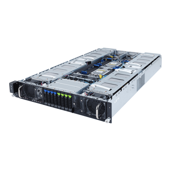
- Page 1 G292-Z43 HPC Server - 2U DP 16 x Gen4 GPU Server (Broadcom solution) User Manual Rev. 1.0...
- Page 2 GIGABYTE's prior written permission. Documentation Classifications In order to assist in the use of this product, GIGABYTE provides the following types of documentation: User Manual: detailed information & steps about the installation, configuration and use of this product (e.g. motherboard, server barebones), covering hardware and BIOS.
- Page 3 Conventions The following conventions are used in this user's guide: NOTE! Gives bits and pieces of additional information related to the current topic. CAUTION! Gives precautionary measures to avoid possible hardware or software problems. WARNING! Alerts you to any damage that might result from doing or not doing specific actions.
- Page 4 Server Warnings and Cautions Before installing a server, be sure that you understand the following warnings and cautions. WARNING! To reduce the risk of electric shock or damage to the equipment: • Do not disable the power cord grounding plug. The grounding plug is an important safety feature.
- Page 5 Electrostatic Discharge (ESD) CAUTION! ESD CAN DAMAGE DRIVES, BOARDS, AND OTHER PARTS. WE RECOMMEND THAT YOU PERFORM ALL PROCEDURES AT AN ESD WORKSTATION. IF ONE IS NOT AVAILABLE, PROVIDE SOME ESD PROTECTION BY WEARING AN ANTI-STATIC WRIST STRAP AT- TACHED TO CHASSIS GROUND -- ANY UNPAINTED METAL SURFACE -- ON YOUR SERVER WHEN HANDLING PARTS.
- Page 6 CAUTION! Risk of explosion if battery is replaced incorrectly or with an incorrect type. Replace the battery only with the same or equivalent type recommended by the manufacturer. Dispose of used bat- teries according to the manufacturer’s instructions.
-
Page 7: Table Of Contents
Table of Contents Chapter 1 Hardware Installation ................... 11 Installation Precautions .................. 11 Product Specifications ..................12 System Block Diagram ................... 15 Chapter 2 System Appearance ..................17 Front View ...................... 17 Rear View ....................... 18 Front Panel Buttons and LEDs ............... 19 Rear System LAN LEDs ................. - Page 8 5-2-4 Legacy Video Select ....................72 5-2-5 AST2500 Super IO Configuration ................73 5-2-6 S5 RTC Wake Settings ...................75 5-2-7 Serial Port Console Redirection ................76 5-2-8 CPU Configuration ....................79 5-2-9 AMI Graphic Output Protocol Policy ...............80 5-2-10 PCI Subsystem Settings ..................81 5-2-11 USB Configuration ....................83 5-2-12 NVMe Configuration ....................85 5-2-13 SATA Configuration....................86 5-2-14 Network Stack Configuration ..................87...
- Page 9 5-8-4 UEFI Application Boot Priorities ................136 Save & Exit Menu ..................137 5-10 ABL POST Codes ..................138 5-10-1 Start Processor Test Points ..................138 5-10-2 Memory test points ....................138 5-10-3 PMU Test Points ....................138 5-10-4 Original Post Code ....................139 5-10-5 CPU test points .....................140 5-10-6 Topology test points ....................140 5-10-7 Extended memory test point .................140 5-10-8 Gnb Earlier init ......................141...
- Page 10 This page intentionally left blank - 10 -...
-
Page 11: Chapter 1 Hardware Installation
Chapter 1 Hardware Installation Installation Precautions The motherboard/system contain numerous delicate electronic circuits and components which can become damaged as a result of electrostatic discharge (ESD). Prior to installation, carefully read the service guide and follow these procedures: • Prior to installation, do not remove or break motherboard S/N (Serial Number) sticker or warranty sticker provided by your dealer. -
Page 12: Product Specifications
Product Specifications NOTE: We reserve the right to make any changes to the product specifications and product-related informa- tion without prior notice. AMD EPYC™ 7002 series processor family Š Dual processors, 7nm technology Š Up to 64-core, 128 threads per processor Š... - Page 13 - Maximum limitation of GPU card: 285mm (L) x 111.5mm (W) x 39.5mm (H) - System is validated for population with a uniform GPU model - Support is not provided for mixed GPU populations - For the latest GPU cards QVL, please contact your GIGABYTE representative Internal I/O 1 x TPM header Š...
- Page 14 System Aspeed® AST2500 management controller Š Management AMI MegaRAC SP-X Solution web interface Š Dashboard Š JAVA Based Serial Over LAN Š HTML5 KVM Š Sensor Monitor (Voltage, RPM, Temperature, CPU Status …etc.) Š Sensor Reading History Data Š FRU Information Š...
-
Page 15: System Block Diagram
System Block Diagram 10/100/1G MLAN 4-bay 2.5” SATA + 4-bay 2.5” U.2 NVMe/SATA PHY(1ch) ASPEED AST2500 2 x 10GbE BASE-T LAN Intel X550-AT2 2 x USB 3.0 CPU0 CPU1 SPI Flash 32MB xGMI2 16-20GT/s AMD ROME AMD ROME “Zen2” Core “Zen2”... - Page 16 This page intentionally left blank Hardware Installation - 16 -...
-
Page 17: Chapter 2 System Appearance
Chapter 2 System Appearance Front View Description Front Panel LED and Buttons GPU Fan (GPU78_FAN) GPU Fan (GPU56_FAN) NOTE! The Green Latch Supports NVMe • Go to the section for detail description of function 2-3 Front Panel Buttons and LEDs LEDs. -
Page 18: Rear View
Rear View 3 4 5 6 7 8 9 10 11 Description System Fan (GPU12E_FAN) VGA Port 10/100/1000 Server Management LAN port Power Button with LED ID Button Reset Button System Status LED LAN Port #2 Active/Link LED 10G LAN Port x 2 LAN Port #1 Active/Link LED USB 3.0 Port x 2 System Fan (GPU56E_FAN) -
Page 19: Front Panel Buttons And Leds
Front Panel Buttons and LEDs No. Name Color Status Description Indicates a link between the system and the network or Green LAN1/2 no access. 1/2. Active/ Green Blink Indicates data trasmission or receiving is occuring. Link LED Indicates no data transmission or receiving is occuring. Indicates locating the HDD. -
Page 20: Rear System Lan Leds
Rear System LAN LEDs 3 4 3 4 Name Color Status Description Yellow 1 Gbps data rate 1GbE Speed Green 100 Mbps data rate 10 Mbps data rate Link between system and network or no access Green 1GbE Link / Blink Data transmission or reception is occurring. -
Page 21: Power Supply Unit (Psu) Led
Power Supply Unit (PSU) LED PSU LED Color Status Description No AC power to all power supplies Blinking Green AC present / Only +12VSB on (PS off) or PSU in Smart Standby Mode 0.5Hz Blinking Green Power supply firmware update AC cord unplugged / AC power lost but a second power supply in parallel still having AC input power Amber... -
Page 22: Hard Disk Drive Leds
Hard Disk Drive LEDs LED#1 LED#2 (Reserved) HDD Present RAID SKU Rebuilding LED1 Locate HDD Fault Access (No Access) Disk LED Green ON(*1) BLINK (*2) (LED on Back Panel) Amber No RAID configuration Green ON(*1) (via HBA) Removed HDD Slot (LED on Back Panel) Amber Green... -
Page 23: Chapter 3 System Hardware Installation
Chapter 3 System Hardware Installation Pre-installation Instructions Computer components and electronic circuit boards can be damaged electrostatic discharge. Working on computers that are still connected to a power supply can be extremely dangerous. Follow the simple guidelines below to avoid damage to your computer or injury to yourself. •... -
Page 24: Removing Chassis Cover
Removing Chassis Cover Before you remove or install the system cover • Make sure the system is not turned on or connected to AC power. Follow these instructions to remove the system cover: Remove the eight screws securing the cover. Slide the cover towards the rear and remove the cover in the direction of the arrow. -
Page 25: Removing And Installing The Fan Duct
Removing and Installing the Fan Duct Follow these instructions to remove/install the fan duct: Lift up to remove the fan duct To install the fan duct, align the tabs at the front of the fan duct with the slots in the system fan compartment as shown in the image below, and then push down the fan duct into chassis until its firmly seats - 25 -... -
Page 26: Installing The Cpu And Heat Sink
Installing the CPU and Heat Sink Read the following guidelines before you begin to install the heat Sink: Always turn off the computer and unplug the power cord from the power outlet before installing the heat sink to prevent hardware damage. Unplug all cables from the power outlets. - Page 27 CPU0 CPU1 - 27 - System Hardware Installation...
- Page 28 Follow these instructions to install the CPU: Align and install the processor on the carrier, making sure to line up the triangle markers on the corner of the CPU to the triangle mark on the corner of the CPU carrier. Slide the carrier assembly into the channels of the carrier bracket Close the carrier bracket so that it firmly latches on to the CPU socket.
- Page 29 • When installing the heat sink over the CPU, use T30-Lobe driver to tighten the 4 captive nuts in sequential order (1g2g3g4). • The screw tightening torque: 8 ± 0.5kgf-cm (17.0± 1.0 lbf-in) System Hardware Installation - 29 -...
-
Page 30: Installing The Memory
Installing the Memory Read the following guidelines before you begin to install the memory: • Make sure that the motherboard supports the memory. It is recommended that memory of the same capacity, brand, speed, and chips be used. • Always turn off the computer and unplug the power cord from the power outlet before installing the memory to prevent hardware damage. -
Page 31: Installing A Memory
3-4-2 Installing a Memory Before installing a memory module, make sure to turn off the computer and unplug the power cord from the power outlet to prevent damage to the memory module. Be sure to install DDR4 DIMMs on this motherboard. Follow these instructions to install the Memory: Insert the DIMM memory module vertically into the DIMM slot, and push it down. - Page 32 RDIMM Maximum Frequency Supported DIMM Frequency (MT/s) DIMMs Populated 1.2V 3200 3200 2933 2933 2933 3DS RDIMM Maximum Frequency Supported DIMM Frequency (MT/s) DIMMs 2S2R Populated 1.2V 2S4R 2933 2666 LRDIMM Maximum Frequency Supported DIMM Frequency (MT/s) DIMMs 2S2R Populated 1.2V 2S4R 3200...
-
Page 33: Installing The Gpu Card
Installing the GPU Card • Voltages can be present within the server whenever an AC power source is connected. This voltage is present even when the main power switch is in the off position. Ensure that the system is powered-down and all power sources have been disconnected from the server prior to installing a PCI card. - Page 34 (For GPU8/GPU9/GPU10/GPU11) (For GPU0/GPU1/GPU2/GPU3) Rear Front System Hardware Installation - 34 -...
- Page 35 - 35 - System Hardware Installation...
- Page 36 For GPU12/GPU13/GPU13/GPU14 Follow these instructions to install the GPU card: [For GPU12/GPU13/GPU13/GPU14] Loosen and remove the two screws securing the PCI cage at the top of the system. [For GPU4/GPU5/GPU6/GPU7] Loosen and remove the single screw at the top of the system and the two screws at the rear of the system securing the PCI cage.
- Page 37 (For GPU4/GPU5/GPU6/GPU7) Rear Front - 37 - System Hardware Installation...
- Page 38 (For GPU12/GPU13/GPU14/GPU15) System Hardware Installation - 38 -...
-
Page 39: Installing A Pci Express Card
Installing a PCI Express Card • Voltages can be present within the server whenever an AC power source is connected. This voltage is present even when the main power switch is in the off position. Ensure that the system is powered-down and all power sources have been disconnected from the server prior to installing a PCI card. - Page 40 System Hardware Installation - 40 -...
- Page 41 Follow these instructions to install a PCI Express x16 card on left side of the system: Loosen the thumbnail screw securing the PCI Express card bracket on the left side of the system. Remove the PCI e card bracket from the system. Install the PCIe card into the bracket.
- Page 42 System Hardware Installation - 42 -...
-
Page 43: Installing The Hard Disk Drive
Reinsert the HDD tray into the slot and close the locking lever. CAUTION! We strongly recommend using enterprise level hard disk drives in the Gigabyte server system. For more information of recommended HDDs, please visit the Gigabyte website: https://www.gigabyte.com and search for the specific product QVL from Support & Downloads. - Page 44 System Hardware Installation - 44 -...
-
Page 45: Replacing The Fan Assembly
Replacing the FAN Assembly CAUTION! Before you remove or install the system fans follow these steps: • Make sure the system is not turned on or connected to the AC power.. • Disconnect all necessary cable connections. Failure to observe these warnings could result in personal injury or damage to the equipment. - Page 46 Airflow direction Airflow direction [For SYS_FAN1/SYS_FAN2] Disconnect the fan cable and then lift up the fan assembly from the chassis. Reverse the previous steps to install the replacement fan assembly. System Hardware Installation - 46 -...
- Page 47 Airflow direction [For GPU12E_FAN/GPU56E_FAN] Disconnect the fan cable and then loosen and remove the screws securing the fan cage. Remove the fan cage from the system Reverse the previous steps to install the replacement fan assembly. - 47 - System Hardware Installation...
- Page 48 Airflow direction CAUTION! • To avoid fan cable damage, please make sure the fan cables are firmly seated in the cable routing hooks. System Hardware Installation - 48 -...
-
Page 49: Replacing The Power Supply
Replacing the Power Supply CAUTION! • In order to reduce the risk of injury from electric shock, disconnect AC power from the power supply before removing it from the system. Follow these instructions to replace the power supply: Pull up the power supply handle and press the retaining clip on the right side of the power supply along the direction of the arrow. -
Page 50: Cable Routing
3-10 Cable Routing System Main Power MB/Top Tray Connector System Fan Power System Hardware Installation - 50 -... - Page 51 CPU Power MB/Top Tray Connector 1 x 3 Power - 51 - System Hardware Installation...
- Page 52 HDD Backplane Board Signal HDD Backplane Board Power System Hardware Installation - 52 -...
- Page 53 Power Distribution Board to HDD Backplane Board Power - 53 - System Hardware Installation...
- Page 54 SlimLine SAS #1 MB/Top Tray Connector SlimLine SAS #2 MB/Top Tray Connector System Hardware Installation - 54 -...
- Page 55 Front Panel IO NVMe - 55 - System Hardware Installation...
- Page 56 NVMe Bo om Connector System Hardware Installation - 56 -...
- Page 57 NVMe Bo om Connector - 57 - System Hardware Installation...
- Page 58 This page intentionally left blank System Hardware Installation - 58 -...
-
Page 59: Chapter 4 Motherboard Components
Chapter 4 Motherboard Components Motherboard Components DIMM_P0_H0 DIMM_P1_L0 DIMM_P0_G0 DIMM_P1_K0 DIMM_P0_F0 DIMM_P1_J0 DIMM_P0_E0 DIMM_P1_I0 CPU0 CPU1 DIMM_P0_A0 DIMM_P1_M0 DIMM_P0_B0 DIMM_P1_N0 DIMM_P0_C0 DIMM_P1_O0 DIMM_P0_D0 DIMM_P1_P0 13 14 Item Description Rear VGA Port Serial Port Connector IPMB Connector 10/100/1000 Server Management LAN Port Power Button with LED ID Button with LED Reset Button (top)/ NMI Button (bottom) - Page 60 System Battery Cable Connector Mezzanine Slot TPM Connector BMC Readiness LED NCSI Cable Connector Motherboard Components - 60 -...
-
Page 61: Jumper Setting
Jumper Setting Default Enable HOST_SMBUS_SEL BIOS defined Clear CMOS CLR_CMOS1 PMBUS_SEL BIOS defined 1 2 3 BIOS_PWD Clear supervisor password Normal [Default] BIOS ROCOVERY BIOS recovery mode Normal [Default] CPU0 CPU1 NCSI Switch Mezzanine Slot Onboard LAN - 61 - Motherboard Components... - Page 62 This page intentionally left blank Motherboard Components - 62 -...
-
Page 63: Chapter 5 Bios Setup
Chapter 5 BIOS Setup BIOS (Basic Input and Output System) records hardware parameters of the system in the EFI on the motherboard. Its major functions include conducting the Power-On Self-Test (POST) during system startup, saving system parameters and loading operating system, etc. BIOS includes a BIOS Setup program that allows the user to modify basic system configuration settings or to activate certain system features. - Page 64 Main This setup page includes all the items in standard compatible BIOS. Advanced This setup page includes all the items of AMI BIOS special enhanced features. (ex: Auto detect fan and temperature status, automatically configure hard disk parameters.) ...
-
Page 65: The Main Menu
The Main Menu Once you enter the BIOS Setup program, the Main Menu (as shown below) appears on the screen. Use arrow keys to move among the items and press <Enter> to accept or enter other sub-menu. Main Menu Help The on-screen description of a highlighted setup option is displayed on the bottom line of the Main Menu. - Page 66 Parameter Description BIOS Information Project Name Displays the project name information. Project Version Displays version number of the BIOS setup utility. Build Date and Time Displays the date and time when the BIOS setup utility was created. BMC Information BMC Firmware Version Displays version number of the BIOS setup utility.
- Page 67 Parameter Description Total Memory Displays the total memory size of the installed memory. (Note1) Memory Speed Displays the frequency information of the installed memory. (Note1) VR Information Version Displays VR version information. AGESA PI Version PI Version Displays AGESA PI version information. Onboard LAN Information LAN1 MAC Address Displays LAN MAC address information.
-
Page 68: Advanced Menu
Advanced Menu The Advanced menu display submenu options for configuring the function of various hardware components. Select a submenu item, then press [Enter] to access the related submenu screen. BIOS Setup - 68 -... -
Page 69: Trusted Computing
5-2-1 Trusted Computing Parameter Description Configuration Select Enable to activate TPM support feature. Security Device Support Options available: Enable/Disable. Default setting is Enable. SPI TPM Support Options available: Enabled/Disabled. Default setting is Enabled - 69 - BIOS Setup... -
Page 70: Psp Firmware Versions
5-2-2 PSP Firmware Versions The PSP Firmware Versions page displays the basic PSP firmware version information. Items on this window are non-configurable. BIOS Setup - 70 -... -
Page 71: Redish Host Interface Settings
5-2-3 Redish Host Interface Settings Parameter Description Redish Host Interface Settings BMC Redish Version Displays the Redish version supported by BMC. BIOS Redish Version Displays the Redish version supported by BIOS. Press [Enter] to select the authentication mode. Authentication Mode Options available: Basic Authentication/Session Authentication. -
Page 72: Legacy Video Select
5-2-4 Legacy Video Select Parameter Description Select between onboard or external VGA support. OnBrd/Ext VGA Select (Note) Options available: Auto/Onboard/External. Default setting is Onboard. This configurable option will be displayed when "Boot Mode Select" is set to Legacy in the (Note) Boot >... -
Page 73: Ast2500 Super Io Configuration
5-2-5 AST2500 Super IO Configuration Parameter Description AST2500 Super IO Configuration Super IO Chip Displays the super IO chip information. - 73 - BIOS Setup... - Page 74 Parameter Description Press [Enter] to configure advanced items. Serial Port (Note1) Š – Enable/Disable the Serial Port (COM). When set to Enabled allows you to configure the Serial port 1/2 settings. When set to Disabled, displays no configuration for the serial port. –...
-
Page 75: S5 Rtc Wake Settings
5-2-6 S5 RTC Wake Settings Parameter Description Enable or disable system wake on alarm event. Select Fixed Time, system will wake on the time (HH:MM:SS) specified. Select Dynamic Time and the Wake system from S5 system will wake at the current time plus an increase in minute(s). Options available: Disabled/Fixed Time/Dynamic Time. -
Page 76: Serial Port Console Redirection
5-2-7 Serial Port Console Redirection Parameter Description Select whether to enable console redirection for specified device. Console COM1/SOL Console redirection enables the users to manage the system from a remote location. Redirection (Note) Options available: Enabled/Disabled. Default setting is Disabled. Selects a COM port for Legacy serial redirection. - Page 77 Parameter Description Bits per second Š – Selects the transfer rate for console redirection. – Options available: 9600/19200/38400/57600/115200. Default setting is 115200. Data Bits Š – Selects the number of data bits used for console redirection. – Options available: 7/8. Default setting is 8. Parity Š...
- Page 78 Parameter Description Redirection COM Port Š – Selects a COM port to display redirection of Legacy OS and Legacy OPROM Messages. – Options available: COM1/SOL. Default setting is COM1/SOL. Resolution Š – On Legacy OS, the number of rows and columns supported in Legacy Console Redirection redirection.
-
Page 79: Cpu Configuration
5-2-8 CPU Configuration Parameter Description CPU Configuration Enable/disable the CPU Virtualization. SVM Mode Options available: Enabled/Disabled. Default setting is Enabled. Controls the Secure Memory Encryption Enable (SMEE) function. SMEE Options available: Enabled/Disabled. Default setting is Enabled. CPU 0 Information Press [Enter] to view more information related to CPU 0. CPU 1 Information Press [Enter] to view more information related to CPU 1. -
Page 80: Ami Graphic Output Protocol Policy
5-2-9 AMI Graphic Output Protocol Policy Parameter Description ASPEED Graphics PCI Adapter ASPEED Graphics Driver Output Select Press [Enter] to select output interface. BIOS Setup - 80 -... -
Page 81: Pci Subsystem Settings
5-2-10 PCI Subsystem Settings Parameter Description PCI Bus Driver Version Displays the PCI Bus Driver version information. U2_P0_P1 / U2_P0_P2 / U2_P0_P3 / Change the PCIe lanes. U2_P1_P0 / U2_P1_P1 / U2_P1_P2 / Options available: U2_P1_P3 / U2_P0_G3 / U2_P1_G1 Disabled / Auto / x16 / x8 x8 / x8 x4 x4 / x4 x4 x8 / x4 x4 x4 x4 Default setting is Auto. - Page 82 Parameter Description If the system has SR-IOV capable PCIe devices, this item Enable/ SR-IOV Support Disable Single Root IO Virtualization Support. Options available: Enabled/Disabled. Default setting is Enabled. Enable/Disable PCI-E AER. PCI-E AER Enabled Options available: Enabled/Disabled. Default setting is Disabled. BIOS Setup - 82 -...
-
Page 83: Usb Configuration
5-2-11 USB Configuration Parameter Description USB Configuration USB Module Version Displays the USB version. USB Controllers Displays the supported USB controllers. USB Devices Displays the USB devices connected to the system. Enable/disable the Legacy USB support fuction. AUTO option disables legacy support if no USB devices are connected. - Page 84 Parameter Description USB mass storage device Start Unit command time-out. Device reset time-out Options available: 10 sec/20 sec/30 sec/40 sec. Default setting is 20 sec. Maximum time the device will take before it properly reports itself to the Host Controller. "Auto" uses default value: for a Root port it is 100 ms, for Device power-up delay a Hub port the delay is taken from Hub descriptor.
-
Page 85: Nvme Configuration
5-2-12 NVMe Configuration Parameter Description NVMe controller and Drive Displays the NVMe devices connected to the system. Information - 85 - BIOS Setup... -
Page 86: Sata Configuration
5-2-13 SATA Configuration BIOS Setup - 86 -... -
Page 87: Network Stack Configuration
5-2-14 Network Stack Configuration Parameter Description Enable/Disable the UEFI network stack. Network Stack Options available: Enabled/Disabled. Default setting is Enabled. Enable/Disable the Ipv4 PXE feature. Ipv4 PXE Support (Note) Options available: Enabled/Disabled. Default setting is Enabled. Enable/Disable the Ipv4 HTTP feature. Ipv4 HTTP Support (Note) Options available: Enabled/Disabled. -
Page 88: Amd Mem Configuration Status
5-2-15 AMD Mem Configuration Status Parameter Description Press [Enter] for configuration of advanced items. Channel A/BC/D/E/F/G/H Š – DIMM0 Presence – DIMM1 Presence CPU 0 – Chipset/Bank Interleave Dram EC Š Dram Parity Š Dimm Sensor Fine Grain Mode Š Press [Enter] for configuration of advanced items. -
Page 89: Iscsi Configuration
5-2-16 iSCSI Configuration Parameter Description Press [Enter] and name iSCSI Initiator. Only IQN format is accecpted. iSCSI Initiator Name Range: from 4 to 223 Add Attempt Press [Enter] for configuration of advanced items. Delete Attempt Press [Enter] for configuration of advanced items. Change Attempt Order Press [Enter] for configuration of advanced items. -
Page 90: Tls Auth Configuration
5-2-17 Tls Auth Configuration Parameter Description Press [Enter] for configuration of advanced items. Enroll Cert Š – Press [Enter] to enroll a certificate • Enroll Cert Using File • Cert GUID Server CA Configuration Input digit character in 1111111-2222-3333-4444- 1234567890ab format. –... -
Page 91: Intel(R) I350 Gigabit Network Connection
5-2-18 Intel(R) I350 Gigabit Network Connection - 91 - BIOS Setup... - Page 92 Parameter Description Press [Enter] to configure advanced items. Link Speed Š – Allows for automatic link speed adjustment. – Options available: Auto Negotiated/10 Mbps Half/10 Mbps Full/100 Mbps Half/100 Mbps Full. Default setting is Auto Negotiated. NIC Configuration Wake On LAN Š...
-
Page 93: Vlan Configuration
5-2-19 VLAN Configuration - 93 - BIOS Setup... - Page 94 Parameter Description Press [Enter] to configure advanced items. Create new VLAN Š VLAN ID Š – Sets VLAN ID for a new VLAN or an existing VLAN. – Press the <+> / <-> keys to increase or decrease the desired values. The valid range is from 0 to 4094.
-
Page 95: Mac Ipv4 Network Configuration
5-2-20 MAC IPv4 Network Configuration Parameter Description Indicates whether network address is configured successfully or not. Configured Options available: Disabled/Enabled. Default setting is Disabled. Enable DHCP Options available: Enabled/Disabled. Default setting is Enabled. (Note) Local IP Address Press [Enter] to configure local IP address. (Note) Local NetMask Press [Enter] to configure local NetMask. -
Page 96: Mac Ipv6 Network Configuration
5-2-21 MAC IPv6 Network Configuration Parameter Description Press [Enter] for configuration of advanced items. Interface Name Š Interface Type Š MAC address Š Host addresses Š Route Table Š Gateway addresses Š DNS addresses Š Interface ID Š Enter Configuration Menu –... -
Page 97: Intel(R) Ethernet Controller X550
5-2-22 Intel(R) Ethernet Controller X550 - 97 - BIOS Setup... - Page 98 Parameter Description Press [Enter] to configure advanced items. Link Speed Š – Allows for automatic link speed adjustment. – Options available: Auto Negotiated/10 Mbps Half/10 Mbps Full/100 Mbps Half/100 Mbps Full. Default setting is Auto Negotiated. NIC Configuration Wake On LAN Š...
-
Page 99: Amd Cbs Menu
AMD CBS Menu AMD CBS menu displays submenu options for configuring the CPU-related information that the BIOS automatically sets. Select a submenu item, then press [Enter] to access the related submenu screen. - 99 - BIOS Setup... -
Page 100: Cpu Common Options
5-3-1 CPU Common Options Parameter Description CPU Common Options Press [Enter] for more options. Custom Core Pstates Š – Allows you to accept or decline custom core pstates. When accepted you can disable or customize ceratin pstates. Performance CCD/Core/Thread Enablement Š... - Page 101 Parameter Description From a workaroud for GCC/C000005 issue for XV Core on CZ A0, setting MSRC001_1029 Decode Configuration (DE_CFG) bit 14 RedirectForReturnDis [DecfgNoRdrctForReturns] to 1. Options available: Auto/1/0. Default option is Auto. Enable/Disable PFEH, cloak individual banks, and mask deferred error Platform First Error Warning interrupts from each bank.
-
Page 102: Df Common Options
5-3-2 DF Common Options Parameter Description DF Common Options Press [Enter] for configuration of advanced items. DRAM scrub time Š – Provides a value that is the number of hours to scrub memory. – Options available: Disabled/1 hour/4 hours/8 hours/16 hours/24 hours/48 hours/Auto. - Page 103 Parameter Description Press [Enter] for more options. NUMA notes per socket Š – Specifies the number of desired NUMA (Non-uniform Memory Access) notes per socket. Zero will attempt to interleave the two sockets together. – Options available: NPS0/NPS1/NPS2/NPS4/Auto. Default option is Auto.
- Page 104 Parameter Description Press [Enter] for more options. GMI encryption control Š – Control GMI link encryption. – Options available: Disabled/Enabled/Auto. Default option is Auto. xGMI encryption control Š – Control xGMI link encryption.Options available: Disabled/Enabled/ Auto. Default option is Auto. CAKE CRC perf bounds control Š...
-
Page 105: Umc Common Options
5-3-3 UMC Common Options Parameter Description UMC Common Options Press [Enter] for more options. Enforce POR Š – Press [Enter] to configure the enforcement of Plan Of Record (POR) which enables / disables restrictions for DDR4 frequency and voltage programming. Memory speeds will be capped at AMD guidelines. - Page 106 Parameter Description Common RAS Š – Press [Enter] to configure Common RAS options. • Data Poisoning • DRAM Post Package Repair • RCD Parity • DRAM Address Command Parity Retry • Max Parity Error Replay DDR4 Common Options • Write CRC Enable (continued) •...
- Page 107 Parameter Description Press [Enter] for more options MBIST Enable Š – Enable or disable Memory MBIST. – Options available: Disabled/Enabled. Default option is Disabled. Data Eye Š – Press [Enter] for more options. • Pattern Select • Pattern Length • Aggressor Channel •...
-
Page 108: Nbio Common Options
5-3-4 NBIO Common Options Parameter Description NBIO Common Options Enable/Disable IOMMU. IOMMU Options available: Enabled/Disabled. Default setting is Disabled. Enables Alternative Routing ID Interpretation. PCIe ARI Support Options available: Disable/Enable/Auto. Default option is Auto. Enables PCIe ten bit tags for supported devices. Auto = Disabled PCIe Ten Bit Tag Support Options available: Disable/Enable/Auto. - Page 109 Parameter Description Press [Enter] for more options. Determinism Control Š – Auto = Use the fused determinism, Manual = User can set customized determinism. – Options available: Manual/Auto. Default option is Manual. cTDP Control Š – Auto = Use the fused TDP, Manual = User can set customized TDP.
- Page 110 Parameter Description Press [Enter] for more options. NBIO RAS Global Control Š – Options available: Manual/Auto. Default option is Auto. NBIO RAS Control Š – 0 = Disabled, 1 = MCA, 2 = Legacy. – Options available: Disabled/MCA/Legacy. Default option is MCA. Egress Poison Severity High Š...
- Page 111 Parameter Description System Hub Watchdog Timer Š – Enter a value. This value specifies the timer interval of the SYSHUB watchdog timer in miliseconds. SLINK Read Response OK Š – This value specifies whether SLINK read response errors are converted to an Okay response. When this value is set to TRUE, read response errors are converted to Okay responses with data of all FFs.
- Page 112 Parameter Description Sync Flood on PCIe Fatal Error Š – When 'Sync Flood on PCIe Fatal Error' is True, PcdAmdPcieSyncFloodOnFatal should be set to True. When 'Sync NBIO RAS Common Options Flood on PCIe Fatal Error' is False, PcdAmdPcieSyncFloodOnFatal (continued) should be set to False.
-
Page 113: Fch Common Options
5-3-5 FCH Common Options Parameter Description FCH Common Options SATA Enable Š – Enable or disable OnChip SATA controller. – Options available: Disabled/Enabled/Auto. Default setting is Auto. SATA RAS Support Š – Enable or disable SATA RAS support. – Options available: Disabled/Enabled/Auto. Default setting is Auto. Sata Disabled AHCI Prefetch Function Š... - Page 114 Parameter Description Press [Enter] for more options. SD Configuration Mode Š SD Dump Options – Select SD Mode. – Options available: SD Dump disabled/SD Dump Enabled. Default setting is SD Dump disabled. Press [Enter] for more options. AC Loss Control Š...
- Page 115 Parameter Description Press [Enter] for more options. ALink RAS Support Š – Options available: Disabled/Enabled/Auto. Default setting is Auto. FCH RAS Options Reset after sync flood Š – Enable AB to forward downstream sync-flood message to system controller. – Options available: Disabled/Enabled/Auto. Default setting is Auto. - 115 - BIOS Setup...
-
Page 116: Ntb Common Options
5-3-6 NTB Common Options Parameter Description NTB Common Options Enable or disable OnChip SATA controller. NTB Enable Options available: Auto/Enable. Default setting is Auto. BIOS Setup - 116 -... -
Page 117: Soc Miscellaneous Control
5-3-7 SOC Miscellaneous Control Parameter Description Soc Miscellaneous Control Enable = Enable ConsoleOut Function for ABL Disable = Disable ConsoleOut Function for ABL ABL Console Out Control Auto = Keep default behavior Options available: Disable/Enable/Auto. Default setting is Auto. Enable = Enable Basic ConsoleOut Function for ABL Disable = Disable Basic ConsoleOut Function for ABL ABL Basic Console Out Control Auto = Keep default behavior... -
Page 118: Amd Pbs Option Menu
AMD PBS Option Menu AMD PBS Option menu displays submenu options for configuring the function of AMD PBS. Select a submenu item, then press [Enter] to access the related submenu screen. Parameter Description AMD PBS Press [Enter] for advanced configurations. Enable or disable SPI Locking for protect ROM part. -
Page 119: Ras
5-4-1 RAS Parameter Description Enable or disable Periodic SMI for polling [MCA Threshold] error. RAS Periodic SMI Control Options Available: Disabled/Enabled. Default option is Enabled. Enter a value. Limits the number of [MCA Threshold and Deferred Error SMI source] SMI Threshold per a unit of time (Defined by [SMI Scale]). - Page 120 Parameter Description PCIe UnCorr GHES Notify Notification type for PCIe uncorrected errors. Type Options Available: Polled/NMI. Default option is NMI. PCIe Root Port Corr Err Mask Enter a value. Intialize the PCIe AER Corrected Error Mask register of Root Port. PCIe Root Port UnCorr Err Enter a value.
-
Page 121: Chipset Setup Menu
Chipset Setup Menu Chipset Setup menu displays submenu options for configuring the function of the North Bridge. Select a submenu item, then press [Enter] to access the related submenu screen. Parameter Description PCIe Link training in 1 or 2 steps. PCIe Link Training Type Options available: 1 Step/2Step. -
Page 122: Server Management Menu
Server Management Menu Parameter Description FRB-2 Timer FRB-2 timer (POST timer). Configure the FRB2 Timer timeout. Options available: 3 minutes/4 minutes/5 minutes/6 minutes. Default setting is 6 FRB-2 Timer minutes. timeout (NOTE) This item is configurable when FRB-2 Timer is set to Enabled. Configure the FRB2 Timer policy. - Page 123 Parameter Description System Event Log Press [Enter] to configure advanced items. View FRU Press [Enter] to view the FRU information. Information BMC network Press [Enter] to configure advanced items. configuration IPv6 BMC Network Press [Enter] to configure advanced items. Configuration - 123 - BIOS Setup...
-
Page 124: System Event Log
5-6-1 System Event Log Parameter Description Enabling / Disabling Options Change this item to enable or disable all features of System Event SEL Components Logging during boot. Options available: Enabled/Disabled. Default setting is Enabled. Erasing Settings Choose options for erasing SEL. Erasing SEL Options available: No/Yes, On next reset/Yes, On every reset. -
Page 125: View Fru Information
5-6-2 View FRU Information The FRU page is a simple display page for basic system ID information, as well as System product information. Items on this window are non-configurable. (Note) The model name will vary depending on the product you have purchased. - 125 - BIOS Setup... -
Page 126: Bmc Network Configuration
5-6-3 BMC Network Configuration Parameter Description BMC network configuration Lan Channel 1 Select to configure LAN channel parameters statically or dynamically (DHCP). Do nothing option will not modify any BMC network parameters Configuration Address source during BIOS phase. Options available: Unspecified/Static/DynamicBmcDhcp. Default setting is DynamicBmcDhcp. -
Page 127: Ipv6 Bmc Network Configuration
5-6-4 IPv6 BMC Network Configuration Parameter Description IPv6 BMC Network Configuration IPv6 BMC Lan Channel 1 Enable/Disable IPv6 BMC LAN channel function. When this item is IPv6 BMC Lan Option disabled, the system will not modify any BMC network during BIOS phase. Options available: Unspecified/Disable/Enable. -
Page 128: Security Menu
Security Menu The Security menu allows you to safeguard and protect the system from unauthorized use by setting up access passwords. There are two types of passwords that you can set: • Administrator Password Entering this password will allow the user to access and change all settings in the Setup Utility. •... -
Page 129: Secure Boot
5-7-1 Secure Boot Parameter Description System Mode Displays the system is in User mode or Setup mode. Enables/Disables Secure Boot. The mode change requires a platform Secure Boot reset. Options available: Disabled/Enabled. Default setting is Disabled. Secure Boot requires all the applications that are running during the booting process to be pre-signed with valid digital certificates. - Page 130 Parameter Description Factory Key Provision Š – Installs factory default Secure Boot keys after the platform resets and the system is in Setup Mode. – Options available: Disabled/Enabled. Default setting is Disabled. Restore Factory Keys Š – Installs factory default Secure Boot key databases. It will force the system in User Mode.
-
Page 131: Boot Menu
Boot Menu The Boot menu allows you to set the drive priority during system boot-up. BIOS setup will display an error message if the legacy drive(s) specified is not bootable. Parameter Description Boot Configuration Number of seconds to wait for setup activation key. 65535 (0xFFFF) Setup Prompt Timeout means indefinite waiting. -
Page 132: Uefi Hard Disk Drive Bbs Priorities
Parameter Description UEFI Hard Disk Drive BBS Press [Enter] to configure the boot priority. Priorities UEFI USB Drive BBS Priorities Press [Enter] to configure the boot priority. UEFI Network Drive BBS Press [Enter] to configure the boot priority. Priorities UEFI Application Boot Priorities Press [Enter] to configure the boot priority. BIOS Setup - 132 -... - Page 133 5-8-1 UEFI Hard Disk Drive BBS Priorities The UEFI hard disk drive BBS priorities submenu allows you to specify the boot device priority from the available UEFI hard disk drives during system boot-up. BIOS setup will display an error message if the legacy drive(s) specified is not bootable.
-
Page 134: Uefi Usb Drive Bbs Priorities
5-8-2 UEFI USB Drive BBS Priorities The UEFI USB drive BBS priorities submenu allows you to specify the boot device priority from the available UEFI USB drives during system boot-up. BIOS setup will display an error message if the legacy drive(s) specified is not bootable. -
Page 135: Uefi Network Drive Bbs Priorities
5-8-3 UEFI NETWORK Drive BBS Priorities The UEFI network drive BBS priorities submenu allows you to specify the boot device priority from the available UEFI network drives during system boot-up. BIOS setup will display an error message if the legacy drive(s) specified is not bootable. -
Page 136: Uefi Application Boot Priorities
5-8-4 UEFI Application Boot Priorities The UEFI application boot priorities submenu allows you to specify the boot device priority from the available UEFI applications during system boot-up. BIOS setup will display an error message if the legacy drive(s) specified is not bootable. BIOS Setup - 136 -... -
Page 137: Save & Exit Menu
Save & Exit Menu The Exit menu displays the various options to quit from the BIOS setup. Highlight any of the exit options then press [Enter]. Parameter Description Save Options Saves changes made and closes the BIOS setup. Save Changes and Exit Options available: Yes/No. -
Page 138: Abl Post Codes
5-10 ABL POST Codes 5-10-1 Start Processor Test Points Entry used for range testing for @b Processor related TPs 0xE000 5-10-2 Memory test points Memory structure initialization (Public interface) 0xE001 SPD Data processing (Public interface) 0xE002 Memory configuration (Public interface) Phase 1 0xE003 DRAM initialization 0xE004... -
Page 139: Original Post Code
ABL Mem - PMU Stage Training Wr 2D 0xE023 ABL Mem - PMU Queue Empty 0xE024 ABL Mem - PMU US message Start 0xE025 ABL Mem - PMU US message End 0xE026 ABL Mem - PMU Complete 0xE027 ABL Mem - PMU - After PMU Training 0xE028 ABL Mem - PMU - Before Disable PMU 0xE029... -
Page 140: Cpu Test Points
ABL Mem - Before OtherTiming 0xE04A ABL Mem - Before UMAMemTyping 0xE04B ABL Mem - Before SetDqsEccTmgs 0xE04C ABL Mem - Before MemClr 0xE04D ABL Mem - Before On DIMM Thermal 0xE04E ABL Mem - Before DMI 0xE04F ABL MEM - End of phase 3 memory code 0xE050 5-10-5 CPU test points Entry point CPU init after training... -
Page 141: Gnb Earlier Init
5-10-8 Gnb Earlier init TP0x90 0xE090 GNB earlier interface 0xE091 GNB internal debug code 0xE092 GNB internal debug code 0xE093 GNB internal debug code 0xE094 GNB internal debug code 0xE095 GNB internal debug code 0xE096 GNB internal debug code 0xE097 GNB internal debug code 0xE098 GNB internal debug code... - Page 142 ABL 2 Begin 0xE0B8 ABL 2 Initialization 0xE0B9 ABL 2 After Training 0xE0BA ABL 2 Debug Synchronization 0xE0BB ABL 2 Error detected 0xE0BC ABL 2 Global memory error detected 0xE0BD ABL 2 End 0xE0BE ABL 3 Begin 0xE0BF ABL 3 Initialziation 0xE0C0 ABL 3 GMI/xGMI Initialization Stage 1 0xB1C0...
- Page 143 ABL 4 APOB Initialization - cold boot 0xE0CA ABL 4 Finalize memory settings - cold boot 0xE0CB ABL 4 CPU Initialize Optimized Boot - cold boot 0xE0CC ABL 4 Gmi Pcie Training - cold boot 0xE0CD ABL 4 Cold boot End 0xE0CE ABL 4 Initialization - Resume boot 0xE0CF...
-
Page 144: Pmu Test Points
Before the memory code calls out to locate a buffer 0xE0F3 After the memory code calls out to locate a buffer 0xE0F4 Before the memory code calls out to locate a buffer 0xE0F5 After the memory code calls out to locate a buffer 0xE0F6 Before the memory code calls out to locate a buffer 0xE0F7... - Page 145 ABL Error for Soc Scan No Die error 0xE2AC ABL Error for Nb Tech Heap Aloc error 0xE2AD ABL Error for No Nb Constructor error 0xE2AE ABL Error for No Tech Constructor error 0xE2AE ABL Error for ABL1b Auto Alocation error 0xE2B0 ABL Error for ABL1b No NB Constructor error 0xE2B1...
- Page 146 ABL Error over clock Mem Init Error 0xE2D5 ABL Error over clock Mem Other Error 0xE2D6 ABL Error for ABL6 General Error 0xE2D7 ABL Error Event Log Error 0xE2D8 ABL Error FATAL ABL1 Log Error 0xE2D9 ABL Error FATAL ABL2 Log Error 0xE2DA ABL Error FATAL ABL3 Log Error 0xE2DB...
- Page 147 ABL Error ABL 2 Mem Init Error 0xE302 ABL Error ABL 4 Mem Init Error 0xE303 ABL Error ABL 6 Mem Init Error 0xE304 ABL Error ABL 1 error repor Error 0xE305 ABL Error ABL 2 error repor Error 0xE306 ABL Error ABL 3 error repor Error 0xE307 ABL Error ABL 4 error repor Error...
-
Page 148: Agesa Post Codes
5-11 Agesa POST Codes 5-11-1 Universal Post Code Universal ACPI entry 0xA001 Universal ACPI exit 0xA002 Universal ACPI abort 0xA003 Universal SMBIOS entry 0xA004 Universal SMBIOS exit 0xA005 Universal SMBIOS abort 0xA006 5-11-2 [0xA1XX] For CZ only memory Postcodes Memory structure initialization (Public interface) 0xA101 SPD Data processing (Public interface) 0xA102... - Page 149 Calculate MaxRdLatency per channel 0xA120 TpProcMemReceiveDqsTraining 0xA121 Set Write Data delay 0xA122 Write test pattern 0xA123 Start read sweep 0xA124 Set Receive DQS delay 0xA125 Read Test pattern 0xA126 Compare Test pattern 0xA127 Update results 0xA128 Start Find passing window 0xA129 TpProcMemTransmitDqsTraining 0xA12A...
- Page 150 Before InitMCT 0xA149 Before OtherTiming 0xA14A Before UMAMemTyping 0xA14B Before SetDqsEccTmgs 0xA14C Before MemClr 0xA14D Before On DIMM Thermal 0xA14E Before DMI 0xA14F End of memory code 0xA150 Entry point S3Init 0xA151 Sending MRS2 0xA180 Sedding MRS3 0xA181 Sending MRS1 0xA182 Sending MRS0 0xA183...
-
Page 151: S3 Interface Post Code
BR Init Mid end 0xA19E BR Init Late entry 0xA19F BR Init Late install protocol 0xA1A0 BR Init Late end 0xA1A1 BR DXE install complete protocol 0xA1A2 UNB install complete PPI 0xA1A3 UNB AfterApLaunch callback entry 0xA1A4 UNB AfterApLaunch callback end 0xA1A5 5-11-3 S3 Interface Post Code Before the S3 save code calls out to allocate a buffer... - Page 152 PspSmmV1 SwSmiCallBack exit, build the S3 save area for resume 0xA511 PspSmmV1 BspSmmResumeVector entry 0xA512 PspSmmV1 BspSmmResumeVector exit 0xA513 PspSmmV1 ApSmmResumeVector entry 0xA514 PspSmmV1 ApSmmResumeVector exit 0xA515 PspP2CmboxV1 entry 0xA516 PspP2CmboxV1 exit 0xA517 // PSP V2 Modules PspPeiV2 entry 0xA521 PspPeiV2 exit 0xA522 PspDxeV2 entry...
- Page 153 PspP2Cmbox Command SpiSetAttrib Handling entry 0xA592 PspP2Cmbox Command SpiGetBlockSize Handling entry 0xA593 PspP2Cmbox Command SpiReadFV Handling entry 0xA594 PspP2Cmbox Command SpiWriteFV Handling entry 0xA595 PspP2Cmbox Command SpiEraseFV Handling entry 0xA596 PspP2Cmbox Command Handling exit 0xA59E PspP2Cmbox Command Handling Fail exit 0xA59F // C2P mailbox Handling PSP C2P mailbox entry base [0xA5BX | Cmd]...
-
Page 154: 0Xa9Xx, 0Xaaxx] Assigned For Agesa Nbio Module
5-11-6 [0xA9XX, 0xAAXX] assigned for AGESA NBIO Module // NbioBase AmdNbioBase PEIM driver entry 0xA900 AmdNbioBase PEIM driver exit 0xA901 AmdNbioBase DXE driver entry 0xA902 AmdNbioBase DXE driver exit 0xA903 // PCIe AmdNbioPcie PEIM driver entry 0xA904 AmdNbioPcie PEIM driver exit 0xA905 AmdNbioPcie DXE driver entry 0xA906... - Page 155 // APCB SMM APCB SMM Entry 0xA924 APCB SMM Exit 0xA925 // [0xA950, 0xA99F] NBIO PPI/PROTOCOL Callback NbioTopologyConfigureCallback entry 0xA950 NbioTopologyConfigureCallback exit 0xA951 MemoryConfigDoneCallbackPpi entry 0xA952 MemoryConfigDoneCallbackPpi exit 0xA953 DxioInitializationCallbackPpi entry 0xA954 DxioInitializationCallbackPpi exit 0xA955 DispatchSmuV9Callback entry 0xA956 DispatchSmuV9Callback exit 0xA957 DispatchSmuV10Callback entry 0xA958...
-
Page 156: 0Xacxx] Assigned For Agesa Ccx Module
GfxConfigEnvInterface entry 0xA984 GfxConfigEnvInterface exit 0xA985 GfxEnvInterfaceCZ entry 0xA986 GfxEnvInterfaceCZ exit 0xA987 GfxMidInterfaceCZ entry 0xA988 GfxMidInterfaceCZ exit 0xA989 GfxIntInfoTableInterfaceCZ entry 0xA98A GfxIntInfoTableInterfaceCZ exit 0xA98B PcieMidInterfaceCZ entry 0xA98C PcieMidInterfaceCZ exit 0xA98D GnbMidInterfaceCZ entry 0xA98E GnbMidInterfaceCZ exit 0xA98F GnbSmuMidInterfaceCZ entry 0xA990 GnbSmuMidInterfaceCZ exit 0xA991 InvokeAmdInitLate entry 0xA992... -
Page 157: 0Xadxx] Assigned For Agesa Df Module
5-11-8 [0xADXX] assigned for AGESA DF Module DF PEI entry 0xAD50 DF DXE entry 0xAD55 DF Ready to Boot entry 0xAD56 DF PEI exit 0xADE0 DF DXE exit 0xADE5 DF Ready to Boot exit 0xADE6 5-11-9 [0xAFXX] assigned for AGESA FCH Module FCH InitReset dispatch point 0xAF01 FCH InitEnv dispatch point... - Page 158 FCH InitEnv AB Link 0xAF51 FCH InitEnv LPC 0xAF52 FCH InitEnv SPI 0xAF53 FCH InitEnv eSPI 0xAF54 FCH InitEnv SD 0xAF55 FCH InitEnv eMMC 0xAF56 FCH InitEnv SATA 0xAF57 FCH InitEnv USB 0xAF58 FCH InitEnv xGbE 0xAF59 FCH InitEnv HwAcpiP 0xAF5F FCH InitMid HwAcpi 0xAF60...
-
Page 159: Bios Post Beep Code (Ami Standard)
5-12 BIOS POST Beep code (AMI standard) 5-12-1 PEI Beep Codes # of Beeps Description Memory not Installed. Memory was installed twice (InstallPeiMemory routine in PEI Core called twice) Recovery started DXEIPL was not found DXE Core Firmware Volume was not found Recovery failed S3 Resume failed Reset PPI is not available...