Table of Contents
Advertisement
Quick Links
TRANSLATION OF THE ORIGINAL INSTRUCTIONS
We advise you to read this manual carefully, as it contains all the instructions for maintaining
the appliance's aesthetic and functional qualities.
For further information on the product: www.smeg.com
Contents
4
4
8
8
8
8
8
9
10
10
11
11
12
12
14
14
16
17
18
19
23
23
26
26
26
27
28
30
32
34
34
37
42
47
48
3
Advertisement
Table of Contents

Related Manuals for Smeg Classica C6GMX9


Summary of Contents for Smeg Classica C6GMX9
-
Page 1: Table Of Contents
5.4 Instructions for the installer 5.5 Electrical connection TRANSLATION OF THE ORIGINAL INSTRUCTIONS We advise you to read this manual carefully, as it contains all the instructions for maintaining the appliance’s aesthetic and functional qualities. For further information on the product: www.smeg.com... -
Page 2: Instructions
Instructions 1 Instructions • Cleaning and maintenance must not be carried out by 1.1 General safety instructions unsupervised children. • Make sure that the flame-spreader Risk of personal injury crowns are correctly positioned in • During use the appliance and its their seats with their respective accessible parts become very hot. - Page 3 Instructions • If you need to move food or at the • Do not try to repair the appliance end of cooking, open the door yourself or without the intervention 5 cm for a few seconds, let the of a qualified technician. steam come out, then open it fully.
- Page 4 Instructions • DO NOT USE THE APPLIANCE • Do not put empty pans or frying TO HEAT ROOMS FOR ANY pans on switched on cooking REASON. zones. • Do not spray any spray products • Do not use steam jets to clean the near the oven.
- Page 5 Instructions Installation • Have the electrical connection performed by authorised • THIS APPLIANCE MUST NOT BE technicians. INSTALLED IN A BOAT OR • The appliance must be connected CARAVAN. to ground in compliance with • This appliance must not be electrical system safety standards.
-
Page 6: Manufacturer Liability
Instructions For this appliance 1.4 Identification plate The identification plate bears the • Ensure that the appliance is technical data, serial number and switched off before replacing the brand name of the appliance. Do not bulb. remove the identification plate for •... -
Page 7: How To Read The User Manual
Instructions To dispose of the appliance: 1.7 How to read the user manual • Cut the power supply cable and This user manual uses the following reading conventions: remove it along with the plug. Instructions Power voltage General information on this user Danger of electrocution manual, on safety and final disposal. -
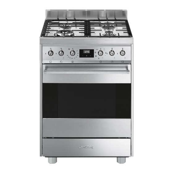
Page 8: Description
Description 2 Description 2.1 General Description 1 Upstand 6 Door 2 Cooking hob 7 Fan 3 Control panel 8 Storage compartment 4 Left bulb Rack/tray support frames 5 Seal... -
Page 9: Cooking Hob
Description 2.2 Cooking hob AUX = Auxiliary burner UR-3c = Ultra-rapid burner SR = Semi-rapid burner 2.3 Control panel 1 Hob burner knobs 2 Indicator light Used for lighting and adjusting the hob The indicator light comes on to indicate that burners. -
Page 10: Other Parts
Description 4 Digital programmer Interior lighting Useful for displaying the current time, setting The appliance’s interior lighting comes on: programmed cooking operations and • when the door is opened; programming the minute minder timer. • when any function is selected, apart from 5 Function knob function. - Page 11 Description Deep tray Ring reducer Useful when using small cookware. WOK ring Useful for collecting fat from foods placed on the rack above and for cooking pies, pizzas and baked desserts. Tray rack Useful when using a wok. Not all accessories are available on some models.
-
Page 12: Use
3 Use High temperature inside the storage compartment 3.1 Instructions Danger of burns High temperature inside the oven • Do not open the storage compartment during use when the appliance is on and still hot. Danger of burns • The items inside the storage compartment could be very hot after •... - Page 13 Malfunctions High temperature inside the storage compartment Any of the following indicate a malfunction and you should contact a service centre: Danger of fire or explosion • Yellowing of the burner plate. • Do not spray any spray product near the •...
-
Page 14: Using The Accessories
3.2 Using the accessories Racks and trays Racks and trays have to be inserted into the Ring reducers side guides until they come to a complete The ring reducers must be placed on the stop. hob grids. Make sure they are placed •... -
Page 15: Using The Hob
3.3 Using the hob Correct positioning of the flame- spreader crowns and burner caps All the appliance’s control and monitoring devices are located together on the front Before lighting the hob burners, make sure panel. The burner controlled by each knob that the flame-spreader crowns are is shown next to the knob. -
Page 16: Using The Oven
3.4 Using the oven Small grill Using only the heat released from Switching on the oven the central element, this function To switch the oven on: allows you to grill small portions of 1. Select the cooking function using the meat and fish for making kebabs, function knob. -
Page 17: Programmer Clock
Fan with round heating element Vapour Clean The combination of the fan and the This function makes cleaning easier round heating element using the steam produced by a little (incorporated in the rear of the quantity of water poured onto the oven) allows you to cook different appropriate groove placed on the foods on several levels, as long as... - Page 18 Timed cooking Setting the time Timed cooking is the function If the time is not set, the oven will which allows a cooking operation not switch on. to be started and then ended after a specific length of time set by the On the first use, or after a power failure, the user.
- Page 19 7. Press the clock key to reset the 4. Use the key to set the required minutes. (for example 1 hour) programmer clock. 5. Press the menu key . The text It is not possible to set a cooking time of more than 10 hours. will appear on the display in sequence with the pre-set cooking To cancel the set programming...
- Page 20 10. Return the function and temperature Minute minder timer knobs to 0. The minute minder timer does not 11. To turn off the buzzer just press any key stop the cooking operation but of the programmer clock. rather informs the user when the set time has run out.
-
Page 21: Using The Storage Compartment
3.6 Using the storage compartment Modifying the set data The storage compartment is at the bottom of 1. Press the clock key the cooker. To open it, pull the handle towards you. It can be used to store 2. Use the value increase and value cookware or metallic objects necessary decrease... - Page 22 Advice for cooking with the Grill Advice for defrosting and proving • Meat can be grilled even when it is put • Place frozen foods without their into the cold oven or into the preheated packaging in a lidless container on the oven if you wish to change the effect of first shelf of the oven.
- Page 23 Cooking information table Weight Temperature Food Function Shelf Time (minutes) (kg) (°C) Lasagne 3 - 4 Static 220 - 230 45 - 50 Pasta bake 3 - 4 Static 220 - 230 45 - 50 Roasted veal Turbo/Round 180 - 190 90 - 100 Pork loin Turbo/Round...
-
Page 24: Cleaning And Maintenance
Cleaning and maintenance 4 Cleaning and maintenance Ordinary daily cleaning Always use specific products only that do 4.1 Instructions not contain abrasives or chlorine-based acids. Improper use Pour the product onto a damp cloth and Risk of damage to surfaces wipe the surface, rinse thoroughly and dry with a soft cloth or a microfibre cloth. -
Page 25: Cleaning The Hob
Cleaning and maintenance 4.3 Cleaning the hob Flame-spreader crowns and burner caps For easier cleaning, the flame-spreader Knobs crowns and the burner caps can be removed. Wash them in hot water and non- Do not use aggressive products abrasive detergent. Carefully remove any containing alcohol or products for encrustation, then wait until they are cleaning steel and glass when... -
Page 26: Cleaning The Door
Cleaning and maintenance 4.4 Cleaning the door 3. To reassemble the door, put the hinges in the relevant slots in the oven, making sure Removing the door that grooved sections A are resting For easier cleaning, the door can be completely in the slots. - Page 27 Cleaning and maintenance Removing the internal glass panes 4. Clean the external glass pane and the previously removed panes. Use For easier cleaning, the internal glass panes absorbent kitchen roll. In case of of the door can be removed. stubborn dirt, wash with a damp sponge 1.
-
Page 28: Cleaning The Oven Cavity
Cleaning and maintenance 4.5 Cleaning the oven cavity Cleaning of racks and trays For the best oven cavity upkeep, clean it Clean the racks and trays with warm water regularly after having allowed it to cool. and non-abrasive detergents. Carefully rinse and dry damp parts. - Page 29 Cleaning and maintenance Vapour Clean • Spray a water and washing up liquid solution inside the oven using a spray Vapor Clean is an assisted nozzle. Direct the spray against the side cleaning procedure which walls, upwards, downwards and facilitates the removal of dirt. towards the deflector.
-
Page 30: Extraordinary Maintenance
Cleaning and maintenance End of the Vapor Clean cycle 4.6 Extraordinary maintenance 4. Open the door and wipe away the less Installing and removing the seal stubborn dirt with a microfibre cloth. To remove the seal: 5. Use a non-scratch sponge with brass •... - Page 31 Cleaning and maintenance Replacing the internal light bulb 4. Slide out and remove the light bulb. Live parts Danger of electrocution • Unplug the appliance from the mains. • Wear protective gloves. 1. Remove all accessories from inside the oven cavity. 2.
-
Page 32: Installation
Installation 5 Installation General information Connection to the gas mains can be made 5.1 Gas connection (not valid for the using a continuous wall steel hose in compliance with the guidelines established by the standards in force. The appliance is For installation in the UK, please preset for natural gas G20 (2H) at a refer to the “Local specifications for... - Page 33 Installation Carefully screw the hose connector 3 to the Connection with a steel hose appliance’s gas connector 1 (½” thread Make the connection to the gas mains ISO 228-1), placing the seal 2 between using a continuous wall steel hose whose them.
- Page 34 Installation Connection to LPG Room ventilation Use a pressure regulator and make the The appliance should be installed in rooms connection on the gas cylinder following that have a permanent air supply in the guidelines set out in the standards in accordance with the standards in force.
-
Page 35: Adaptation To Different Types Of Gas
Installation 5.2 Adaptation to different types of In case of operation with other types of gas, the burner nozzles must be changed and the minimum flame adjusted on the gas taps. Replacing nozzles 1. Remove the grids, burner caps and flame-spreader crowns in order to access the burner cups. - Page 36 Installation Adjusting the minimum setting for LPG Tighten the screw located at the side of the cock rod clockwise all the way. Following adjustment to a gas other than the one originally set in the factory, replace the gas setting label on the appliance with the one corresponding to the new gas.
- Page 37 Installation Gas types and Countries Gas types GB-IE FR-BE 1 Natural gas G20 • • • • • • • • • • 20 mbar • G20/25 20/25 mbar 2 Natural gas G20 • 25 mbar 3 Natural gas G25.1 •...
- Page 38 Installation Burner and nozzle characteristics tables 1 Natural gas G20 - 20 mbar Rated heating capacity (kW) Nozzle diameter (1/100 mm) Pre-chamber (printed on nozzle) (F3) Reduced flow rate (W) 1400 2 Natural gas G20 - 25 mbar Rated heating capacity (kW) 1.10 Nozzle diameter (1/100 mm) Pre-chamber (printed on nozzle)
- Page 39 Installation 6 LPG G30/31 - 30/37 mbar Rated heating capacity (kW) Nozzle diameter (1/100 mm) Pre-chamber (printed on nozzle) Reduced flow rate (W) 1400 Rated flow rate G30 (g/h) Rated flow rate G31 (g/h) 7 LPG G30/31 - 37 mbar Rated heating capacity (kW) 1.10 Nozzle diameter (1/100 mm)
-
Page 40: Positioning
Installation 5.3 Positioning Any wall units positioned above the worktop of the appliance must be at a Heavy appliance minimum distance of at least Y mm. If a Crushing hazard hood is installed above the hob, refer to the hood instruction manual to ensure the correct clearance is left. - Page 41 Installation Appliance overall dimensions 600 mm 600 mm B - Class 2 subclass 1 min. 150 mm (Built-in appliance) 900 - 915 mm 750 mm 450 mm 600 mm Minimum distance from side walls or other flammable material. Minimum cabinet width (=A). C - Class 2 subclass 1 (Built-in appliance) The appliance must be installed by...
- Page 42 Installation Dimensions of the appliance: locations of Positioning and levelling gas and electric connections (mm) Heavy appliance Risk of damage to the appliance • Insert the front feet first and then the rear ones. After making the electrical and/or gas connections, screw the four adjustable feet supplied with the appliance.
- Page 43 Installation 3. Assemble the fastening bracket. Fastening to the wall The anti-tip devices must be installed in order to prevent the appliance from tipping over. 1. Screw the wall fastening plate to the rear of the appliance. 4. Align the base of the hook on the fastening bracket with the base of the slot on the wall fastening plate.
- Page 44 Installation 5. Align the base of the fastening bracket 7. Move the bracket onto the wall and with the ground and tighten the screws to mark the position of the holes to be fix the measurements. drilled in the wall. 8.
-
Page 45: Instructions For The Installer
Installation 5.4 Instructions for the installer Assembling the upstand • The plug must be accessible after The upstand provided is an installation. Do not bend or trap the integral part of the product; it must power cable. be fastened to the appliance prior •... -
Page 46: Electrical Connection
Installation 5.5 Electrical connection The appliance can work in the following modes: Power voltage • 220-240 V 1N~ Danger of electrocution • Have the electrical connection performed by authorised technicians. • Use personal protective equipment. 3 x 1.5 mm² three-core cable. •...