Table of Contents
Advertisement
Quick Links
Advertisement
Table of Contents

Related Manuals for Furuno FI-304


Summary of Contents for Furuno FI-304
- Page 4 Introduction Thank you for choosing FI-30 Wind Data instrument. We are convinced that you will appreciate all the valuable information either you are a cruiser or a racer. It is important that you are following this instruction regarding installation and operation. If the instrument are to be used in a Nexus Network, there are some systems settings that are dependent on where the transducers are installed, i.e.
-
Page 5: Table Of Contents
Part specifications...6 Installation...8 Installing the instrument...9 2.1.1 Installing cable ...11 2.1.2 Connections in Nexus Network...11 2.1.3 Connection of log transducer...12 First start ...13 Initialising the instrument in a Nexus Network ...13 Re-initialising the instrument...13 Operation...14 About this manual ...14 How to use the 4 push-buttons ...15 4.2.1 PAGE...15 4.2.2... - Page 6 5.2.4 C24 Temperature offset... 26 C30 Compass Settings... 26 5.3.1 C31 True or magnetic course, MAG... 26 5.3.2 C32 Magnetic deviation, VAR... 26 5.3.3 C33 Autodeviation ... 26 5.3.4 C34 Check the Autodeviation ... 26 5.3.5 C35 Clear the Autodeviation... 27 5.3.6 C36 Adjust the Compass alignment ...
-
Page 7: Part Specifications
Part specifications FI-30 Compass Data is delivered with all parts for mounting. Check prior to installation. Compass Data instrument Qty. Description Instrument, FI-30 Compass Data Instrument front cover Drill template Operator’s Manual Pin bolts for instrument mounting Nuts for instrument mounting Tube of silicon grease Connection cover 4-pol screw terminal... -
Page 9: Installation
Installation You can install the FI-30 Compass in three different ways: The compass transducer connected directly to the FI-30 Compass instrument By using the connection kit when both log and wind transducers are installed with a single cable to the FI-30 Compass instrument. The installation may also include a FI-30 Server where all transducers may be connected. -
Page 10: Installing The Instrument
Installing the instrument Place the adhesive drill template on the desired location for the instrument. Drill the 2 holes using a 5 mm ( ") drill for the two pin bolts. Use a 63 mm (2½ ") hole saw to machine the clearance hole for the instrument connection socket. - Page 11 Apply silicon paste to the instrument connection pins at the back of the instrument. Press the jack plug onto the instrument pins. Press the cable in to the cable leads. Mount the connection back cover with the screw. Your instrument installation is done!
-
Page 12: Installing Cable
2.1.1 Installing cable The power cable is connected via a 3A fuse from the battery or at the boats fuse panel and direct to the instrument or Server. One red and one black power wire is included. Note, Set C71 ON (see 5.4.1). Always connect a 3 AMP fuse between Power supply and instrument. -
Page 13: Connection Of Log Transducer
2.1.3 Connection of log transducer If you have another log instrument i.e. a FI-30 Log, you may connect the single log pulse wire from that instrument to the Compass Data instrument terminal 4. From log transducer 3A Fuse If you don’t have a log instrument, but want to install a log transducer, use the connection box (Art. -
Page 14: First Start
First start At each power on, the instrument will first show all segments lit up, then the ID number and software version [VER]. Number 8 is the fixed ID when the Compass transducer is connected direct at the instrument and the setting in C71 is on (default setting). -
Page 15: Operation
Operation About this manual Each time a push-button is referred to in this manual, the push-button name will appear in bold and CAPITAL letters, e.g. PAGE. Unless otherwise stated, the push-button presses are momentary. Each time a function is mentioned in the text, it will be in brackets and in the same format, where possible, as displayed, e.g. -
Page 16: How To Use The 4 Push-Buttons
How to use the 4 push-buttons COMPASS HEADING INFOTEXT SUB- FUNCTION CLEAR DOWN 4.2.1 PAGE A press on PAGE, changes the mode page of the graphical display. It scrolls in a circular pattern, one step for every press. The PAGE button is also used to move the cursor when in edit mode. A press on PAGE moves the cursor in a circular pattern, one step to the right for every press. -
Page 17: Calibration
4.2.6 Calibration To access calibration mode, press and hold SET more than 2 seconds. To return to main function mode, press SET when the text return [RET] is displayed. 4.2.7 Lighting The instrument uses red back lighting for both the display and the 5 push-buttons. -
Page 18: Main Function
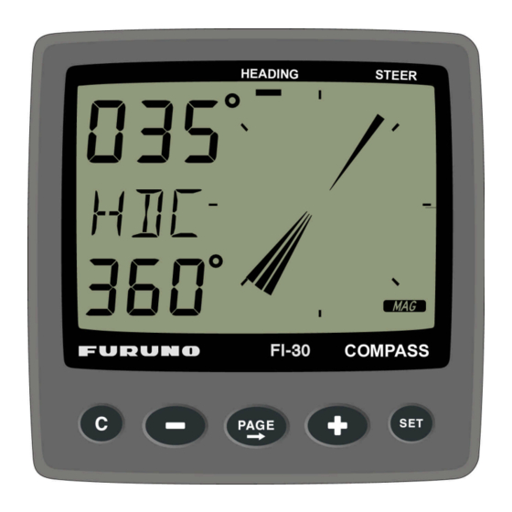
Main function Top data is COMPASS HEADING. Top data is either magnetic or true HEADING and your choice is set in the set-up. When magnetic Compass course is selected, the small MAG sign is lit on the LCD. Analogue function Press the PAGE button to change from Compass heading to steer reference. -
Page 19: Sub-Functions
Sub-functions Select sub-function with PLUS or DOWN. Information text for the sub-function is displayed. You may also ”park” your favourite function so it will automatically be displayed after power on. Press PAGE and SET together to ”park” the displayed function. The display will flash once to confirm that you have ”parked”... -
Page 20: Advanced Use Of (Str) Mem
FI-30 Server with a wind transducer. For the [BTW] and [CTS] functions you will need any NMEA GPS, Decca or Loran C navigator to be connected. Also, if you have installed a FI-30 Autopilot, and it is activated, you may change the course or wind angle by using the STR function. -
Page 21: Steer Reference [Btw], Option
This steer function will give course to steer, true or magnetic relative bearing to Waypoint, including compensation for drift. It must be used together with a GPS or Decca/ Loran C navigator connected to the NEXUS network (at the Server instrument). -
Page 22: Tactical Use Of [Mem]
4.5.7 Tactical use of [MEM] Function [MEM] is used to discover the smallest of wind shifts during upwind or downwind sailing, but it is your tactical decision wheter to tac or to stay on course. The Compass Data instrument will automatically keep track on wheter you are using the starboard or port MEM if the course difference between each trim is more than 45°. -
Page 23: 4.5.10 Trip Log [Trp], Option
4.5.10 Trip log [TRP], option The text [TRP] is displayed and will show trip distance from 0.00 to 99.9 nautical miles, kilometre or miles. After 99.9, 0.00 is displayed. Clear trip by pressing CLEAR. 4.5.11 Water temperature [TMP], option The text [TMP] is displayed with water temperature in Celsius or Fahrenheit. - Page 24 When using the Compass Data in a Network with more than 3 transducers, we recommend you to use the FI-30 Server. One Nexus Network power/data cable is used to connect all instruments. You will have NMEA 0183 in/out. Depth information will (if used) be repeated at more than one FI-30 instrument.
-
Page 25: Calibration / Set-Up
Calibration / Set-up It is important to carefully calibrate and set-up the instrument. The values are stored in a non volatile memory. To access calibration PAGE, press and hold SET more than 2 seconds. To select a calibration code, press DOWN, PLUS and MODE as required. To return to normal operation mode, press SET when the text return [rEt] is displayed. -
Page 26: C15 Beep When Key Is Pressed
5.1.4 C15 Beep when KEY is pressed Setting KEY On will make a beep at every KEY-press, and when KEY is OFF, There is no beep. 5.1.5 C16 Reference pointer On/OFF Setting REF On will show a reference pointer in the true direction as a steer indicator in the Compass graphical mode. -
Page 27: C23 Unit For Temperature
5.2.3 C23 Unit for temperature Select degree Celsius [C] or degree Fahrenheit [F]. 5.2.4 C24 Temperature offset By adding a positive or [-] negative value here, it will be added as an offset before displayed as the temperature. C30 Compass Settings To return to normal mode, press SET when the text [rET] is displayed. -
Page 28: C35 Clear The Autodeviation
if successful, the text [CHK Atd] will appear again, otherwise, ERR 17 or ERR 19 will appear, i.e. the difference between the last Autodeviation and this Autocheck is to big to be accepted. Make a new Autocheck, and if you still get ERR 19, make a new Autodeviation since the last one was probably disturbed. -
Page 29: C69 Pitch Adjustment
5.3.9 C69 Pitch adjustment This adjustment is valid only if roll is selected in C73 (you have to exit and enter the calibration again after C73 is set to Roll). Adjustment of the pitch offset. Mount the pitch transducer according to the instructions. Adjust the offset so the pitch is displaying 00°... -
Page 30: C70 Configure Fi-30
C70 Configure FI-30 To return to normal mode, press SET when the text [rET] is displayed. In the configuration you will be able to tell the Nexus Network where you have installed the log and wind transducer. This is important because you may optionally install those transducers at the Server instead of the instrument. -
Page 31: Connection Of Trim Button
5.4.4 Connection of trim button 5.4.5 C74 Demo mode The Compass Data instrument has a built in demonstration mode. All values are simulated in this mode. It is convenient to learn the functions of the instrument by using this mode. Every 7th second the text DEM will appear to alert you that demo mode is selected. -
Page 32: Maintenance And Fault Finding
Maintenance and fault finding Maintenance To clean the instrument, use only mild soap solution and rinse with water. Do not use detergents or high pressure washing equipment. At least once a year, check all your connections and apply additional silicon paste at each connection point. Always use the instrument cover for protection, when not in use. -
Page 33: Error Messages
2. Speed and distance functions: No reading [ --- ] C13 should be ON. See 5.1.2 Check that setting C72 is according to your installation. Check that the impeller is rotating easy and freely i.e. is free from vegetation Check that there is no remaining anti fouling paint inside the through-hull fitting. 6.2.3 Error messages The following messages may appear on the display:... -
Page 34: Specifications
RS232 PC port. The PC interface will be a very useful tool to control and monitor real time data, or when editing Waypoints to/from PC-file or to/from FI-30 GPS or Server. For users who writes there own software, please contact FURUNO and ask for FI-30 Application notes. -
Page 35: Equipment Lists
PART # MODEL 000-041-864 FI-301 000-041-865 FI-301-SERVER 000-041-866 FI-301-SERVER/SENSOR MULTI CONTROL W/SERVER & SENSORS 000-041-867 FI-302 000-041-868 FI-302-SENSOR 000-041-869 FI-303 000-041-870 FI-303-SENSOR 000-041-871 FI-304 000-041-872 FI-305 000-041-873 FI-306 000-041-874 FI-307 000-041-875 FI-308 000-041-876 FI-309 000-041-877 FI-310 ACCESSORIES PART # MODEL... -
Page 36: Abbreviations
Abbreviations ADJust Apparent Apparent Wind Angle Apparent Wind Speed BATtery Boat SPeed Bearing To Waypoint Celsius CALibration CONfiguration DEMonstration mode Fahrenheit Heading KiloMetre KnoTS Liquid Crystal Display MAGnitic Miles per Hour Mixture NAVigation NeXT leg RETurn SEA dampening Speed Over Ground STAtic TeMPerature TRiM...