Table of Contents
Advertisement
Quick Links
Advertisement
Table of Contents

Related Manuals for First Alert DWH-47


Summary of Contents for First Alert DWH-47
- Page 1 DWH-400 DWH-47...
-
Page 2: Introduction
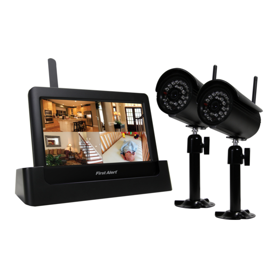
BRK Brands, Inc. is a subsidiary of Jarden Corporation (NYSE: JAH). First Alert® is a registered trademark of the First Alert Trust. To obtain warranty service, contact the Consumer Affairs Division at 1-800-323-9005, Monday through Friday, 7:30 a.m. - 5 p.m., Central Standard Time. - Page 3 INTRODUCTION KEY PRODUCT FEATURES MAIN DESCRIPTION Four channel H.264 wireless digital video recorder with 7” 16:9 LCD Touch Screen and internet access suitable for applications such as high-end residen- tial - new or remodel, light commercial, small business/retail, small warehouse or small grocery.
-
Page 4: Table Of Contents
INTRODUCTION TABLE OF CONTENTS CONTENTS ECTION ESCRIPTION UMBER Introduction Safety Product Overview What is in the Box DVR Controls Front Panel Side Panel & Display Indicators Installation Installing Cameras & Setting up the Wireless Receiver System Operation 10-24 Main Menu Screens Camera Setup 11-12 Camera Pairing... -
Page 5: Safety
We, First Alert / BRK Brands, Inc. declare under our sole responsibility that the device to which this declaration Under Industry Canada regulations, this radio transmitter may only operate using an antenna of a type and maximum (or lesser) gain relates: Complies with Part 15 of the FCC Rules. - Page 6 Digital Wireless Camra 4 CHANNEL WIRELESS 7” LCD DVR...
-
Page 8: Product Overview
PRODUCT OVERVIEW CAMERA, DVR & DOCKING CRADLE CAMERA Antenna Connection Link Status Green LED Light Sensor Power Indicator Red LED Microphone DVR & DOCKING CRADLE Fold Up Power /Mute Antenna Button AC Power Connection RJ-45 Fold Out Ethernet Stand SD Card Slot AC Power Connection... -
Page 9: Installation
INSTALLATION CAMERAS & WIRELESS RECEIVER INSTALLING CAMERAS 1. Select the position for the camera and secure the camera stand. (Screws and anchors are supplied. Use an appropriate screw type for the mounting surface.) 2. Screw the camera onto the bracket. 3. -
Page 10: System Operation
SYSTEM OPERATION LIVE VIEW SCREEN LIVE VIEW MAIN SCREEN DVR STATUS CAMERA STATUS INDICATORS INDICATORS Your DVR operates through a series of screens that let you choose groups of operations. The Live View Screen lets you view the connected camera transmissions. - Page 11 SYSTEM OPERATION LIVE VIEW SCREEN LIVE VIEW SCREENS The Live View Screen displays in 2 views - Quad View or Full View. Quad View displays the images in 4 quadrants (only displays cameras that are ON). Tap a quadrant to display single camera view / full view. Tap on that image again to return to Quad View.
- Page 12 SYSTEM OPERATION MAIN SCREEN MAIN SCREEN POP-UP MENUS Tapping on the Pop-up Menu tab brings you to the Main Menu icons. From here you can configure your Internet, Cameras, adjust the volume and get to the system settings menus. Internet Connection Menu Camera View Menu 1.
-
Page 13: Camera Setup
SYSTEM OPERATION CAMERA SETUP CAMERA SETUP MENU Tap CAMERA SETUP from the System Setup Menu to access the camera setup options: Pairing, Camera On and Brightness. Camera Setup-Main Menu CAMERA PAIRING Pairing Timer Pairing Failed Your camera is paired to the monitor at the factory to channel 1. To add new camera(s) to your system, you have to pair it to the different channel(s). -
Page 14: Camera Brightness Adjustment
SYSTEM OPERATION CAMERA SETUP CAMERA ACTIVATION Camera Setup-Camera Activation An X indicates a camera is OFF, a check indicates ON. Tap on the camera to turn it ON or OFF. NOTE: Ensure the cameras are paired to the receiver for SCAN or QUAD to function properly. Camera “ON” can only be selected when camera has been paired to system. -
Page 15: Recorder Setup Menu
SYSTEM OPERATION RECORDER SETUP RECORDER SETUP MENU Tap RECORDER SETUP from the System Setup Menu to access the Recorder setup options: Motion Detection, E-mail Alert and Schedule Record. Record Setup Menu MOTION DETECTION SENSITIVITY Recorder Setup-Motion Detection Sensitivity Tap the camera’s to set the sensitivity to Off, Low or High. Default = low. The screen will return to the Motion Detection screen after 10 seconds or when you press the Back icon . - Page 16 SYSTEM OPERATION RECORDER SETUP E-MAIL ALERT Recorder Setup-Email Alert The system can notify you when it detects motion from any camera by sending you an email alert. The email alert contains information such as the time that motion was detected and by which camera. In order to enable the Email Alert function, you must enter both incoming and outgoing email addresses.
- Page 17 SYSTEM OPERATION RECORDER SETUP SCHEDULE RECORD Recorder Schedule Setup Menu Up to 5 scheduled recording sessions are available in a single day. You are limited to the size of the SD card for how long a total recording time you have. These recording sessions must begin and end within a single 24-hour period.
-
Page 18: Playback
SYSTEM OPERATION PLAYBACK RECORD LIST Playback-Date Folder Menu Tap on the highlighted day containing the recording you want to view. The RECORD LIST screen will display that day’s recordings listed in a folder. If you tap on a day that is not highlighted, a folder displays with no recordings listed. - Page 19 SYSTEM OPERATION PLAYBACK PLAYBACK CONTROLS Playback Controls 1. Tap on the recording you want to view. It displays on the screen. 2. Tap on any area of the screen that does not have control icons to bring up the playback progress bar. Tap that area again to close it.
- Page 20 SYSTEM OPERATION ALARM SETUP ALARM SETUP Alarm Setup Menu PERIOD This selection allows you to select the alarm/ siren duration when Motion Detection is turned on and motion is detected. 1. Tap Period. The Set Siren Duration screen displays. 2. Select the alarm duration time required. 3.
-
Page 21: System Setup
SYSTEM OPERATION SYSTEM SETUP SYSTEM SETUP System Setup Menu POWER SAVING Power Saving Setup Menu In Power Saving mode, the monitor will shut off the monitor after being idle for 2 minutes. Press Power button on top of the Monitor once to reactive the monitor. If a motion detection event or scheduled recording begins, the monitor turns back on automatically. - Page 22 SYSTEM OPERATION SCREEN AUTO-LOCK SETUP SCREEN AUTO LOCK Screen Auto Lock Menu In Auto Lock mode, the monitor will enter screen lock mode after it has been idle for 2 minutes. Auto Lock disables the touch screen and removes the icons from the display. 1.
- Page 23 SYSTEM OPERATION TIME SETUP TIME Date, Time, Clock Alarm and Timer Setup Menu From the TIME icon you can access the CLOCK ALARM, TIME SETTING and TIMER menus. Clock Alarm Clock Alarm Menu This feature operates as an independent alarm clock. It does not affect the operation of live video or recording video.
- Page 24 SYSTEM OPERATION TIME SETUP Time Setting Time Setting Menu This screen contains fields to set the Month, Day, Year, Hour, Minute and AM/PM. Tap TIME SETTING on the SYSTEM SETUP/TIME screen to display the Time Setting screen. 1. Tap on each field to set it. Use UP/DOWN arrows to set the field or tap on AM/PM to toggle between the two choices.
- Page 25 SYSTEM OPERATION TIME SETUP Timer Timer Menu This feature operates as an independent countdown timer. It does not affect the operation of live video or recording video. Tap TIMER on the SYSTEM SETUP/TIME screen to display the Timer Setting screen. 1.
- Page 26 SYSTEM OPERATION FORMAT STORAGE FORMAT STORAGE Format Storage Screen When using an SD card other than the one provided, it is highly recommended that you format the card using these procedures. Formatting any SD card deletes all files on that card. Tap TIMER on the SYSTEM SETUP/TIME screen to display the Time Setting screen.
- Page 27 SYSTEM OPERATION SYSTEM UPGRADE SYSTEM UPGRADE Format Storage Screen To upgrade the firmware from the vendor website, you must download and store it in the SD card root directory. 1. Tap on START; a confirmation statement displays. 2. Tap OK to proceed to format storage or tap CANCEL to discontinue. System Upgrade Confirmation Screen 3.
- Page 28 SYSTEM OPERATION LANGUAGE LANGUAGE Screen Auto Lock Menu The DEFAULT icon is where you change the language for the DVR. English is the default language. If you change the language, all system settings default to the original factory settings. You will have to reenter any specialized settings.
- Page 29 REMOTE ACCESS NETWORK SETUP REMOTE ACCESS This DWH Series Video Security System lets you view live video from your iPhone, iPad, or Android smart phone or tablet. Apps are available through the iTunes App Store or the Android Market. We recommend OMGuard as it has been tested with this DVR. Up to 2 remote users can access live video at the same time as long as they have the User ID (DID) code and security code.
- Page 30 REMOTE ACCESS INTERNET SETUP Internet Setup Internet Setup - DHCP Tap INTERNET SETUP icon to display the Internet Setup screen. From there select either Static IP and DHCP (Dynamic Host Configuration Protocol), depending on the type of internet connect you have. DHCP is a protocol used by networked devices (clients) to obtain various parameters necessary for the clients to operate in an Internet Protocol (IP) network.
-
Page 31: Default
REMOTE ACCESS SECURITY CODE Security Code Internet Setup - DHCP Set up your security code to limit who can have access to the system from a remote location. The default is 123456. Note: A Security Code must be entered to gain remote access. 1. - Page 32 REMOTE ACCESS NETWORK INFORMATION Network Information Network Information Tap NETWORK INFORMATION icon to display the Network Information screen. This screen provides information about your firmware for your DVR and and of the four cameras that have been paired to your system.
- Page 34 QUICK TIPS QUICK TIPS INFORMATION QUICK TIPS The Quick Tips screen provides additional details on important subjects of system operation. 1. Tap on a subject to display the information.. 2. Tap to return to the previous screen Quick Tips Main Menu Page 34...
- Page 35 QUICK TIPS QUICK TIPS INFORMATION Page 35...
-
Page 36: Appendix
APPENDIX TROUBLESHOOTING TROUBLESHOOTING TROUBLE SHOOTING RROR OSSIBLE AUSE OLUTIONS Cable from power adapter is loose or Confirm that all cables are connected correctly. System is not receiving power is unplugged. No power at electrical Confirm that the power adapter is securely connected to the back of the unit. or is not powering up outlet. -
Page 37: System Map
APPENDIX SYSTEM MAP SYSTEM MAP Connect to Internet? Internet Icon Charge Only? No Internet. Camera Scan Quad Cam 1 Cam 2 Cam 3 Cam 4 Icon Alarm +/- Volume Icon Speaker +/- Cameras Info (i) Record List Calendar Records Icon Settings Cam 1 Cam 2... -
Page 38: Specifications
APPENDIX SPECIFICATIONS TECHNICAL SPECIFICATIONS SPECIFICATIONS EVICE ARAMETER PECIFICATION Channels Screen Type 7” LCD 16:9 Monitor Resolution 800 x 480 Video Format NTSC (default)/PAL 2.4 GHz secure digital wireless with 18 transmission channels using Frequency Wireless Parameters Hopping Spread Spectrum (FHSS) technology Compression Format H.264 Recording Resolution... -
Page 39: Warranty
PRODUCT LIMITED WARRANTY BRK Brands, Inc., (“BRK”) the maker of First Alert® brand products warrants that for a period of one year from the date of purchase (the “Warranty Period”), this product will be free from defects in material and workmanship. BRK, at its sole option, will repair or replace this product or any component of the product found to be defective during the Warranty Period. - Page 40 BRK Brands, Inc. ©2012 a Jarden Corporation Company (NYSE:JAH) 3901 Liberty Street Road, Aurora, IL 60504-8122 Phone: 630-851-7330 Tech Services: 800-323-9005 www.brkelectronics.com M08-xxxx-000...