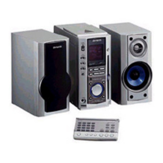
Aiwa XR-MS3 Service Manual
Hide thumbs
Also See for XR-MS3:
- Operating instructions manual (68 pages) ,
- Service manual (26 pages) ,
- Service manual (16 pages)
Table of Contents
Advertisement
Quick Links
All manuals and user guides at all-guides.com
SERVICE MANUAL
COMPACT DISC
STEREO SYSTEM
• This Service Manual is the "Supplement" and replaces "Simple Manual"
XR-MS3 (EZ,K), (S/M Code No. 09-004-422-6T2).
• This Service Manual is for XR-MS3 (EZBM) Black color.
• This Service Manual contains information about the difference between
XR-MS3 (EZBM,KSM) and XR-MS3 (EZ). If requiring the other information,
see Service Manual of XR-MS3 (U,EZ), (S/M Code No. 09-002-422-6R1).
• This Service Manual does not include "CD ELECTRICAL SECTION".
These items will be issued in the next Suplement.
XR-MS3
BASIC TAPE MECHANISM : 2ZM-1 R10NM
BASIC CD MECHANISM : TN-CCD1001-902M
SYSTEM
SPEAKER
EZ : SX-M7
XR-MS3
K : SX-MS7
S/M Code No. 09-007-422-6S1
EZ,K
REMOTE
CONTROLLER
EZ : RC-AAT03(B)
K : RC-AAT03
Advertisement
Table of Contents

Summary of Contents for Aiwa XR-MS3
- Page 1 • This Service Manual is the “Supplement” and replaces “Simple Manual” XR-MS3 (EZ,K), (S/M Code No. 09-004-422-6T2). • This Service Manual is for XR-MS3 (EZBM) Black color. • This Service Manual contains information about the difference between XR-MS3 (EZBM,KSM) and XR-MS3 (EZ). If requiring the other information, see Service Manual of XR-MS3 (U,EZ), (S/M Code No.
-
Page 2: Specifications
All manuals and user guides at all-guides.com SPECIFICATIONS <FM tuner section> <General> Tuning range 87.5 MHz to 108 MHz Power requirements 230 V AC, 50 Hz Usable sensitivity (IHF) 16.8 dBf Power consumption EZ : 57 W Antenna terminals 75 ohms (unbalanced) K : 68 W Standby power consumption EZ : 1.7 W (power-economizing <MW tuner section>... -
Page 3: Electrical Main Parts List
All manuals and user guides at all-guides.com ELECTRICAL MAIN PARTS LIST REF. NO. PART NO. KANRI DESCRIPTION REF. NO. PART NO. KANRI DESCRIPTION 87-010-196-080 CHIP CAPACITOR,0.1-25 87-010-194-080 CAP, CHIP 0.047 8A-CJ5-601-010 C-IC,LC876580W-5N98 87-010-196-080 CHIP CAPACITOR,0.1-25 87-070-246-010 IC,GP1U271X 87-A12-033-090 CAP,E 6800-25 SMG30L 87-A20-909-010 IC,LA4663 87-010-409-080... - Page 4 All manuals and user guides at all-guides.com REF. NO. PART NO. KANRI DESCRIPTION REF. NO. PART NO. KANRI DESCRIPTION C411 87-010-404-080 CAP, ELECT 4.7-50V 87-026-689-080 PROTECTOR,1A 60V 491 C412 87-010-404-080 CAP, ELECT 4.7-50V WH005 87-A90-507-010 HLDR,WIRE 2.5-4P C413 87-010-404-080 CAP, ELECT 4.7-50V C414 87-010-497-080 CAP, ELECT 4.7-35V...
- Page 5 All manuals and user guides at all-guides.com REF. NO. PART NO. KANRI DESCRIPTION REF. NO. PART NO. KANRI DESCRIPTION C354 87-010-175-080 CAP 560P C717 87-012-286-080 CAP,U 0.01-25 C355 87-010-178-080 CHIP CAP 1000P C719 87-012-286-080 CAP,U 0.01-25 C356 87-010-260-040 CAP,E 47-25 SME C720 87-012-195-080 C-CAP,U 100P-50CH...
- Page 6 All manuals and user guides at all-guides.com REF. NO. PART NO. KANRI DESCRIPTION REF. NO. PART NO. KANRI DESCRIPTION C865 87-010-196-080 C-CAP,S 0.1-25 ZF<EZ> L942 87-A50-019-010 COIL,OSC LW(COI) 856KHZ C866 87-010-405-080 CAP,E 10-50 M 11L SME<EZ> L981 8Z-ZA1-665-010 COIL,AM PACK 2(TOK)<EZ> C867 87-012-286-080 C-CAP,U 0.01-25 KB<EZ>...
- Page 7 All manuals and user guides at all-guides.com WIRING – 1 (MAIN / VM) <1 / 2>...
- Page 8 All manuals and user guides at all-guides.com WIRING – 1 (MAIN / VM) <2 / 2> – 8 –...
- Page 9 All manuals and user guides at all-guides.com SCHEMATIC DIAGRAM - 1 (MAIN 1/2 (AMP) / HP-JACK) – 9 –...
- Page 10 All manuals and user guides at all-guides.com SCHEMATIC DIAGRAM - 2 (MAIN 2/2 (MICON)) – 10 –...
- Page 11 All manuals and user guides at all-guides.com WIRING – 2 (FRONT / HP-JACK) – 11 –...
- Page 12 All manuals and user guides at all-guides.com SCHEMATIC DIAGRAM - 3 (FRONT) – 12 –...
- Page 13 All manuals and user guides at all-guides.com WIRING - 3 (TAPE) – 13 –...
- Page 14 All manuals and user guides at all-guides.com SCHEMATIC DIAGRAM - 4 (TAPE / DECK / RELAY) – 14 –...
- Page 15 All manuals and user guides at all-guides.com SCHEMATIC DIAGRAM - 5 (VM) – 15 –...
- Page 16 All manuals and user guides at all-guides.com WIRING – 4 (PT) – 16 –...
-
Page 17: Schematic Diagram - 6 (Pt)
All manuals and user guides at all-guides.com SCHEMATIC DIAGRAM - 6 (PT) – 17 –... - Page 18 All manuals and user guides at all-guides.com WIRING – 5 (EZ : TUNER) – 18 –...
- Page 19 All manuals and user guides at all-guides.com SCHEMATIC DIAGRAM - 7 (EZ : TUNER) – 19 –...
-
Page 20: Wiring - 6 (K : Tuner)
All manuals and user guides at all-guides.com WIRING – 6 (K : TUNER) – 20 –... - Page 21 All manuals and user guides at all-guides.com SCHEMATIC DIAGRAM - 8 (K : TUNER) – 21 –...
- Page 22 All manuals and user guides at all-guides.com WIRING – 7 (DECK / RELAY) – 22 –...
- Page 23 All manuals and user guides at all-guides.com MECHANICAL EXPLODED VIEW 1 / 1 P.C.B P.C.B SHLD PLATE 2ZM-1 HT-SINK P.C.B PLATE,SHLD P.C.B P.C.B HT-SINK SH,CD COVER P.C.B CHAS,MAIN P.C.B TN-CCD1001 – 23 –...
-
Page 24: Mechanical Parts List
All manuals and user guides at all-guides.com MECHANICAL PARTS LIST 1 / 1 REF. NO. PART NO. KANRI DESCRIPTION REF. NO. PART NO. KANRI DESCRIPTION 1 8A-CJ5-016-010 KNOB,RTRY JOG 45 87-NF8-220-010 DMPR,150 2 8A-CJ5-217-010 PLATE,JOG 46 8A-CL5-311-010 LEVER,EJECT 3 8A-CJ5-017-010 REFLECTOR,JOG 47 8A-CJ5-004-010 PANEL,SIDE L<K>... -
Page 25: Speaker Parts List
All manuals and user guides at all-guides.com SPEAKER PARTS LIST <EZ : SX-M7, K : SX-MS7 > REF. NO. PART NO. KANRI DESCRIPTION 1 8A-CJ5-422-010 GRILLE,FRAME ASSY Y<K> 1 8A-CL5-404-010 GRILLE,FRAME ASSY B<EZ> 2 8A-CJ5-415-010 TERMINAL 3 8A-CJ5-405-010 PANEL,SP<K> 3 8A-CL5-408-010 PANEL,SP B<EZ>... - Page 26 All manuals and user guides at all-guides.com 2–11, IKENOHATA 1–CHOME, TAITO-KU, TOKYO 110, JAPAN TEL:03 (3827) 3111 9301978 0251431 Printed in Singapore...


