Table of Contents
Troubleshooting

Related Manuals for Carrier TruVu UC683T


Summary of Contents for Carrier TruVu UC683T
- Page 1 ™ ™ Carrier ©2021 · Catalog No. 11-808-852-01 · 12/3/2021...
- Page 2 Verify that you have the most current version of this document from www.hvacpartners.com, the Carrier Partner Community website, or your local Carrier office. Important changes are listed in Document revision history at the end of this document. Carrier ©2021. All rights reserved.
-
Page 3: Table Of Contents
Contents What is the TV-UC683T? ............................1 Specifications ................................ 2 Zone sensors ................................. 6 Touchscreen devices ............................6 To mount the TV-UC683T ............................. 7 Wiring for power ..............................8 To wire for power ..............................8 Addressing the TV-UC683T through the Service port ................... 9 To set the IP address ............................ - Page 4 Contents Device tab ................................47 Ports tab ................................48 BACnet tab ................................48 Modbus tab ................................. 48 Security tab ................................. 48 Local Network tab .............................. 49 To communicate through the BACnet/Service port network................52 To communicate locally through the Rnet port ....................54 To set up a Local Access connection in the i-Vu®...
-
Page 5: What Is The Tv-Uc683T
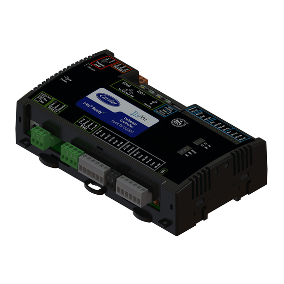
Provides 8 universal inputs, 6 binary outputs, 2 analog outputs, and 1 universal output • The universal output can be configured as binary, analog, or pulse-width modulated analog TruVu™ UC683T CARRIER CORPORATION ©2021 Installation and Start-up Guide All rights reserved... -
Page 6: Specifications
Rnet port for connecting ZS sensors, an Equipment Touch, an TruVu™ ET Display, and Wireless Adapter for wireless sensors • Service USB port for connecting locally to controller setup pages, the TruVu™ ET Display, or the Carrier wireless service adapter •... - Page 7 Use an external transformer if your devices exceed the maximum power. Service port USB 2.0 host port for setting up the controller and troubleshooting through a local connection to a computer, connecting to the TruVu™ ET Display, or the Carrier wireless service adapter. Comm port For future use.
- Page 8 Do not change the position of the End of Net switch at temperatures below - 22°F (-30C) to ensure proper operation and electrical connectivity. Physical Fire-retardant plastic ABS, UL94-5VA Terminal blocks and Screw-type terminal blocks. connectors 0.2 in (5.08 mm) pitch connectors TruVu™ UC683T CARRIER CORPORATION ©2021 Installation and Start-up Guide All rights reserved...
- Page 9 EN50491-3:2009, Part 3: Electrical safety requirements for Home and Building Electronic Systems (HBES) and Building Automation and Control Systems (BACS) Low Voltage Directive: 2014/35/EU RoHS Compliant: 2015/863/EU TruVu™ UC683T CARRIER CORPORATION ©2021 Installation and Start-up Guide All rights reserved...
-
Page 10: Zone Sensors
• The TruVu™ ET Display requires a 24 Vdc external power source. CAUTION A touchscreen device can share a power supply with the Carrier controller if: • The power source shared by the controller and Equipment Touch is AC power. -
Page 11: To Mount The Tv-Uc683T
Use flat washers to prevent the screw head from deforming the plastic. 7.78 in. (19.77 cm) 5.88 in. (14.94 cm) 5.3 in. (13.45 cm) 4.50 in. (11.43 cm) Depth: 2.00 in (5.08 cm) TruVu™ UC683T CARRIER CORPORATION ©2021 Installation and Start-up Guide All rights reserved... -
Page 12: Wiring For Power
The TV-UC683T is powered by a Class 2 power source. Take appropriate isolation measures when mounting it in a control panel where non-Class 2 circuits are present. • Carrier controllers can share a power supply as long as you: • Maintain the same polarity. -
Page 13: Addressing The Tv-Uc683T Through The Service Port
Local Network tab (page 13) and the Local Network (page 49) tab. You can connect the TV-UC683T to a computer using either the Carrier wireless service adapter or a USB cable. NOTE You cannot access the Service port by plugging an Ethernet cable into Eth0 or Eth1. - Page 14 Open a web browser on the computer Navigate to http://local.access or http://169.254.1.1 to see the controller setup pages. See To set up the controller through the Service Port (page 46) for detailed information. TruVu™ UC683T CARRIER CORPORATION ©2021 Installation and Start-up Guide All rights reserved...
-
Page 15: To Set The Ip Address
On the controller setup Ports tab under IP Port, select Custom Static. Enter the IP Address, Subnet Mask, and Default Gateway addresses that the network administrator gave you. Click Save. TruVu™ UC683T CARRIER CORPORATION ©2021 Installation and Start-up Guide All rights reserved... -
Page 16: To Set The Port S1 Address And Baud Rate
Autobaud does not work unless there is a device on the network, whether Carrier or third party, that has the baud rate already set. You can manually set the baud rate on more than one device, as long as the rate is the same for every device. -
Page 17: Addressing A Network Of Controllers Using The Controller Setup Local Network Tab
Addressing a network of controllers using the controller setup Local Network tab You can use the controller setup Local Network tab to discover Carrier TruVu™ devices on a single network. You can configure them and assign addresses to each one using one of the methods described below. -
Page 18: Method 2: To Address When You Do Not Know The Serial Numbers
One technician alone can address the controllers on a mobile device showing the Local Network page by plugging the Carrier wireless service adapter into a controller's Service Port. Then, with the computer, move to each controller within 100 ft. of the adapter. Pressing the DSC button on the controller displays a blue dot in the table where the addressing information can be entered. -
Page 19: Wiring For Communications
See Wiring devices to the TV-UC683T's Act Net port (page 19). Default for MS/TP is 76.8 kbps. Default for Modbus is 38.4 kbps. See To set up the controller through the Service port (page 46). TruVu™ UC683T CARRIER CORPORATION ©2021 Installation and Start-up Guide All rights reserved... -
Page 20: Wiring Specifications
BACnet Broadcast Management Device (BBMD). Do not configure more than one BBMD per subnet as this may cause circular routes. See "Setting up BACnet Broadcast Management Devices (BBMDs)" in SiteBuilder or i-Vu® Help. TruVu™ UC683T CARRIER CORPORATION ©2021 Installation and Start-up Guide All rights reserved... -
Page 21: To Wire To A Bacnet Ms/Tp Network
BACnet: You can wire a third-party BACnet device to the TV-UC683T's Eth0, Eth1 port or Port S1. See the BACnet Integration Guide for the TV-UC683T. Modbus: You can wire a third-party Modbus master or slave device to Port S1. See Modbus Integration Guide for the TV-UC683T. TruVu™ UC683T CARRIER CORPORATION ©2021 Installation and Start-up Guide All rights reserved... -
Page 22: Wiring Devices To The Tv-Uc683T's Rnet Port
See the device's Installation and Start-up Guide for complete wiring instructions. NOTES • ZS sensors, a Wireless Adapter, and an Equipment Touch can share the same Rnet. • The Rnet communicates at a rate of 115.2 kbps. TruVu™ UC683T CARRIER CORPORATION ©2021 Installation and Start-up Guide All rights reserved... -
Page 23: Wiring Devices To The Tv-Uc683T's Act Net Port
Wiring devices to the TV-UC683T's Act Net port Supports a combination of up to 5 Act Net addresses, as follows: • Address 1 is reserved for the Carrier actuator • Address 2 and 3 are reserved for the VAV Zone II Secondary Duct •... - Page 24 (91.44 meters). The bus should be wired with copper conductors of an appropriate size (18 AWG or larger) to compensate for voltage drop and ensure that bus voltage does not drop below 19.2 Vac or 21.6 Vdc. TruVu™ UC683T CARRIER CORPORATION ©2021 Installation and Start-up Guide All rights reserved...
-
Page 25: Wiring Inputs And Outputs
The TV-UC683T can perform pulse counting for dry contact or voltage inputs if you assign the input to a Pulse to Analog Input microblock. See To adjust input and output properties (page 28). TruVu™ UC683T CARRIER CORPORATION ©2021 Installation and Start-up Guide All rights reserved... -
Page 26: Outputs
NOTE The PWM output signal is intended to directly control the speed of an ECM-type fan, eliminating the need for an external converter board. WARNING Do not apply voltage to the universal output if the DIP switch is set to Analog. TruVu™ UC683T CARRIER CORPORATION ©2021 Installation and Start-up Guide All rights reserved... -
Page 27: Wiring Specifications
Acceptable voltage drop in the wire from the controller to the controlled device • Resistance (Ohms) of the chosen wire gauge • Maximum current (Amps) the controlled device requires to operate TruVu™ UC683T CARRIER CORPORATION ©2021 Installation and Start-up Guide All rights reserved... -
Page 28: To Wire Inputs And Outputs
WARNING Do not apply line voltage (mains voltage) to the controller's ports and terminals. The Gnd terminal is shared by the inputs/outputs to the right and left of it. The TV-UC683T has connections for two separate busses. TruVu™ UC683T CARRIER CORPORATION ©2021 Installation and Start-up Guide All rights reserved... - Page 29 NOTE Connect the shield wire to the – terminal with the ground wire. Do not connect the shield wire at the other end of the cable as this will cause a ground loop error. TruVu™ UC683T CARRIER CORPORATION ©2021 Installation and Start-up Guide All rights reserved...
- Page 30 ○ Connect binary and analog output wiring to the screw terminals on the TV-UC683T and to the controlled device. Connect the ground wire to the AO outputs' terminals. TruVu™ UC683T CARRIER CORPORATION ©2021 Installation and Start-up Guide All rights reserved...
- Page 31 See Troubleshooting inputs and outputs (page 60). NOTE You can install connector covers (sold separately, part #PLM-KIT) by snapping them over the terminal block sections on the top and bottom of the controller. TruVu™ UC683T CARRIER CORPORATION ©2021 Installation and Start-up Guide All rights reserved...
-
Page 32: To Adjust Input And Output Properties
To verify each output's operation, lock each output to a known condition on the I/O Points tab, then verify that the equipment operates correctly. See Troubleshooting inputs and outputs (page 60). TruVu™ UC683T CARRIER CORPORATION ©2021 Installation and Start-up Guide All rights reserved... -
Page 33: Input Values
You can set up a custom translation table (page 38) on the driver's Custom Translation Tables pages in the i- Vu® interface. The control program must have one Pulse to Analog Input microblock for each pulse counting input. TruVu™ UC683T CARRIER CORPORATION ©2021 Installation and Start-up Guide All rights reserved... -
Page 34: Output Values
0–10 Vdc actuator so that when the PID signal is 100%, the TV-UC683T output is 10 Vdc. Similarly, when the PID signal is 50%, the TV-UC683T output is 5 Vdc. TruVu™ UC683T CARRIER CORPORATION ©2021 Installation and Start-up Guide All rights reserved... -
Page 35: Resolution Values
When the control program's signal to the microblock is on, if Polarity is set to: normal—output is on reversed—output is off NOTE Regardless of Polarity, the output will be off if the TV-UC683T loses power. TruVu™ UC683T CARRIER CORPORATION ©2021 Installation and Start-up Guide All rights reserved... -
Page 36: Find And Upload In The I-Vu® Interface
When complete, a check mark under Status indicates a successful upload. NOTES If an error message appears, click on the message to view an explanation. ○ For details, see the i-Vu® Help. ○ TruVu™ UC683T CARRIER CORPORATION ©2021 Installation and Start-up Guide All rights reserved... -
Page 37: Adjusting The Tv-Uc683T Driver Properties
If unsuccessful, the indicate failure point will transition to an idle state for 30 seconds before attempting to communicate again. Change this field only if directed by Technical Support. TruVu™ UC683T CARRIER CORPORATION ©2021 Installation and Start-up Guide All rights reserved... - Page 38 You can unlock a device for 24 hours to make IP address changes. Configuration from other devices on the local network for 24 hours Debug Enable Debug Messages Enable only if directed by Carrier Control Systems Support. TruVu™ UC683T CARRIER CORPORATION ©2021 Installation and Start-up Guide All rights reserved...
-
Page 39: Device
Critical Equipment 128–191 Urgent 192–255 Normal Priority of Off-Normal BACnet priority for Alarms. Priority of Fault BACnet priority for Fault messages. Priority of Normal BACnet priority for Return-to-normal messages. TruVu™ UC683T CARRIER CORPORATION ©2021 Installation and Start-up Guide All rights reserved... -
Page 40: Calendars
Uncheck the types of alarms you do not want the recipient to get. Calendars Calendars are provided in the driver for BACnet compatibility only. Instead, use the Schedules feature in the i-Vu® interface. TruVu™ UC683T CARRIER CORPORATION ©2021 Installation and Start-up Guide All rights reserved... -
Page 41: Common Alarms
In a typical i-Vu® system, the Notification Class is 1; however, if needed, you can associate a different notification class with the alarm. See Notification Classes (page 35) to set up alarm delivery options for a specific Notification Class. TruVu™ UC683T CARRIER CORPORATION ©2021 Installation and Start-up Guide All rights reserved... -
Page 42: Specific Events
For the input to use the translation table, go to the control program's Properties page > I/O Points tab. Click the analog input in the Name column. On the Details tab, set Sensor Type (Scaling Method) to Non-Linear, Custom Table #__. TruVu™ UC683T CARRIER CORPORATION ©2021 Installation and Start-up Guide All rights reserved... -
Page 43: Bacnet Controller Properties
IP addresses that you define. These can be all private IP addresses and/or a list of IP addresses. Follow the instructions in the i-Vu® interface to set up the BACnet firewall. TruVu™ UC683T CARRIER CORPORATION ©2021 Installation and Start-up Guide All rights reserved... -
Page 44: Network Diagnostics - Statistics
FIFO errors, frame errors, length errors, missed errors, and overrun errors. Transmit Errors (total)—All errors related to transmitted packets such as aborted errors, carrier errors, dropped errors, FIFO errors, heartbeat errors, and window errors. Dropped Packets—Packets dropped by the TV-UC683T's Ethernet interface. -
Page 45: Network Diagnostics - Packet Capture
NOTE Clicking Get capture file generates the port's .pcap file. If the port has a .pcap file from a previous capture, that file will be overwritten. Extract the .pcap file from the .tgz file. Open the .pcap file in Wireshark. TruVu™ UC683T CARRIER CORPORATION ©2021 Installation and Start-up Guide All rights reserved... -
Page 46: Act Net Bus
(can be found as a label on the actuator). New Device Address Select a new bus address from the drop-down list. TruVu™ UC683T CARRIER CORPORATION ©2021 Installation and Start-up Guide All rights reserved... - Page 47 3. Chose a unique address for the new device and click Accept. Wait until the operation is successful. 4. Repeat the steps 2 and 3 for the remainder of the removed devices. 5. Verify that there are no longer Duplicate Address on the network errors. TruVu™ UC683T CARRIER CORPORATION ©2021 Installation and Start-up Guide All rights reserved...
-
Page 48: Communication Status
The Flow Calibration Archive page shows measured flow and sensor readings that were entered in the i-Vu® Test and Balance tool or through the stand-alone Test & Balance Utility. TruVu™ UC683T CARRIER CORPORATION ©2021 Installation and Start-up Guide All rights reserved... -
Page 49: To Set Up Network Statistic Trends
System Options > System Settings > General tab. Select the second option to set a value for this trend only. TruVu™ UC683T CARRIER CORPORATION ©2021 Installation and Start-up Guide All rights reserved... -
Page 50: To Set Up The Controller Through The Service Port
You can communicate with the TV-UC683T through a web browser by connecting a computer to the controller's Service Port using either the Carrier wireless service adapter or a USB cable. NOTE You cannot access the Service port by plugging an Ethernet cable into Eth0 or Eth1. -
Page 51: Device Tab
BACnet Object Device Instance Autogenerated—(Default) The Device Instance is automatically set to a number using the IP Address, Subnet information, and the Carrier vendor ID 16. Assigned—Lets you enter a specific number that is unique on the BACnet network. Device Name Autogenerated—(Default) The Device Name is automatically set as the word... -
Page 52: Ports Tab
Vu® server IP address, thus blocking communication with the i-Vu® server, you can disable the controller's BACnet Firewall on the controller setup Security tab. NOTE You can enable the BACnet Firewall only in the i-Vu® interface. TruVu™ UC683T CARRIER CORPORATION ©2021 Installation and Start-up Guide All rights reserved... -
Page 53: Local Network Tab
Creates .csv file of the data in the table, limited to 256 devices. Click Discover to populate the table with your TruVu™ devices that are on a single network communicating with the connected TruVu™ controller. TruVu™ UC683T CARRIER CORPORATION ©2021 Installation and Start-up Guide All rights reserved... - Page 54 To resolve a mismatch, select the device(s) by clicking the Select checkbox and then clicking the Resolve button. The subnet mask and default gateway addresses of the selected devices change to match the connected controller. TruVu™ UC683T CARRIER CORPORATION ©2021 Installation and Start-up Guide All rights reserved...
- Page 55 NOTE If a device's IP address is the loopback address (127.0.0.1), it is considered unconfigured and unlocked. The IP address, subnet mask, and default gateway fields are blank in the Ports and Local Network tabs. You can configure it in the Local Devices table. TruVu™ UC683T CARRIER CORPORATION ©2021 Installation and Start-up Guide All rights reserved...
-
Page 56: To Communicate Through The Bacnet/Service Port Network
65535 - searches for an available network number from 65531 to 65534. If any of these numbers are ○ not available, you will have to assign a network number and enter it. 13 Click Apply. TruVu™ UC683T CARRIER CORPORATION ©2021 Installation and Start-up Guide All rights reserved... - Page 57 18 On the navigation tree, right-click the controller that you are connected to and select Module Status. If a Modstat report appears, the i-Vu® application is communicating with the controller. TruVu™ UC683T CARRIER CORPORATION ©2021 Installation and Start-up Guide All rights reserved...
-
Page 58: To Communicate Locally Through The Rnet Port
Connect the other end of the 3-wire cable to the TV-UC683T's Rnet port as shown in the drawing above in step 1. Connect the 3-pin connector to the portion of the USB link kit shown in the drawing below, then connect the USB connector to the computer. TruVu™ UC683T CARRIER CORPORATION ©2021 Installation and Start-up Guide All rights reserved... -
Page 59: To Set Up A Local Access Connection In The I-Vu® Interface
14 Type rnet here in the dialog box, then click OK. 15 On the Properties page, click Module Status. If a Modstat report appears, the i-Vu® application is communicating with the controller. TruVu™ UC683T CARRIER CORPORATION ©2021 Installation and Start-up Guide All rights reserved... -
Page 60: Troubleshooting
Troubleshooting Troubleshooting If you have problems mounting, wiring, or addressing the TV-UC683T, contact Carrier Control Systems Support. LEDs TruVu™ UC683T CARRIER CORPORATION ©2021 Installation and Start-up Guide All rights reserved... - Page 61 White 1 blink The Blink button on the controller No action required every setup Local Network tab has been second for pressed seconds TruVu™ UC683T CARRIER CORPORATION ©2021 Installation and Start-up Guide All rights reserved...
- Page 62 White 1 blink The Blink button on the controller No action required every setup Local Network tab has been pressed second for 15 seconds TruVu™ UC683T CARRIER CORPORATION ©2021 Installation and Start-up Guide All rights reserved...
-
Page 63: To Configure Custom Prog Led
• On the controller setup ModStat tab—See To set up the controller through the Service Port (page 46). See Module Status field descriptions (page 66) in the Appendix. TruVu™ UC683T CARRIER CORPORATION ©2021 Installation and Start-up Guide All rights reserved... -
Page 64: Troubleshooting Inputs And Outputs
Click the Name of any input or output whose name is red (indicates an error) to open its dialog box. On the Details tab, scroll down to see the Reliability field under BACnet Configuration. TruVu™ UC683T CARRIER CORPORATION ©2021 Installation and Start-up Guide All rights reserved... -
Page 65: To Get A Device Log
To get a Device Log If Carrier Control Systems Support instructs you to get the controller's Device Log containing diagnostic information for troubleshooting: Select the TV-UC683T in the i-Vu® navigation tree. -
Page 66: To Get The Tv-Uc683T's Serial Number
Use the same polarity for all of them. You can purchase the 3 A, fast-acting, 5mm x 20mm glass fuse from Littelfuse, mfr part #0235003.HXP. TruVu™ UC683T CARRIER CORPORATION ©2021 Installation and Start-up Guide All rights reserved... -
Page 67: To Revert To Default Settings
We highly recommend that you revert the defaults settings only under the guidance of Carrier Control Systems Support. To erase volatile memory data and restore factory default configuration settings, use AppLoader to download the appropriate clipping. -
Page 68: To Take The Tv-Uc683T Out Of Service
UC683T by shutting down communication from the TV-UC683T to the i-Vu® application. When Out of Service, i- Vu® no longer communicates properties, colors, trends, etc. On the i-Vu® navigation tree, select the TV-UC683T. On the Properties page, check Out of Service. Click Accept. TruVu™ UC683T CARRIER CORPORATION ©2021 Installation and Start-up Guide All rights reserved... -
Page 69: Compliance
Cet appareil numérique de la classe A est conforme à la norme NMB-003 du Canada. BACnet Compliance Compliance of listed products to requirements of ASHRAE Standard 135 is the responsibility of BACnet International. BTL is a registered trademark of BACnet International. ® TruVu™ UC683T CARRIER CORPORATION ©2021 Installation and Start-up Guide All rights reserved... -
Page 70: Appendix - Module Status Field Descriptions
Gives the current status of the controller's networks. See LEDs (page 56) for all possible conditions. System error message history High-severity errors since the last memory download. Shows the most recent 10 messages. See NOTE below this table. TruVu™ UC683T CARRIER CORPORATION ©2021 Installation and Start-up Guide All rights reserved... - Page 71 See NOTE below this table. Core and Base board hardware Gives the following information about the controller's boards: • Type and board numbers that are used internally by Carrier. • The manufacture date and serial number. Number of BACnet Objects The number of BACnet objects that were created in the device and the number of those objects that are network visible.
-
Page 72: Document Revision History
Changed Real time clock specification to "up to 3 days" from "at X-PM-BM-O least 3 days". Changed EU RoHS compliance code. Rephrased Act Net addresses to list fixed addresses. * For internal use only TruVu™ UC683T CARRIER CORPORATION ©2021 Installation and Start-up Guide All rights reserved... - Page 74 Carrier ©2021 · Catalog No. 11-808-852-01 · 12/3/2021...