Canon imageRUNNER 2545 Series Service Manual
Hide thumbs
Also See for imageRUNNER 2545 Series:
- User manual (582 pages) ,
- Service manual digest (116 pages) ,
- Sending and facsimile manual (321 pages)
Table of Contents
Troubleshooting

Related Manuals for Canon imageRUNNER 2545 Series


Summary of Contents for Canon imageRUNNER 2545 Series
- Page 1 imageRUNNER 2545/2535 Series Service Manual Rev2 Product Outline Function Periodic Servicing Parts Replacing and Cleaning Adjustments Troubleshooting Error Code Service Mode Installation Appendix...
- Page 2 This manual is copyrighted with all rights reserved. Under the copyright laws, this manual may changes in the contents of this manual over a long or short period, Canon will issue a new not be copied, reproduced or translated into another language, in whole or in part, without the edition of this manual.
- Page 3 Explanation of Symbols The following rules apply throughout this Service Manual: The following symbols are used throughout this Service Manual. Each chapter contains sections explaining the purpose of specific functions and the relationship between electrical and mechanical systems with reference to the timing of Symbols Explanation Symbols...
-
Page 4: Table Of Contents
Contents Operation --------------------------------------------------------------------------- 1-11 Power Switch ------------------------------------------------------------------------------- 1-11 Description of Control Panel ------------------------------------------------------------ 1-11 Technology Safety Precautions Basic Configuration -----------------------------------------------------------2-2 Functional Configuration --------------------------------------------------------- 2-2 CDRH Act --------------------------------------------------------------------- 0-13 Basic sequence ----------------------------------------------------------------------------- 2-2 Laser Safety ------------------------------------------------------------------ 0-13 Original Exposure System --------------------------------------------------2-3 Handling of Laser System ------------------------------------------------ 0-13 Construction ------------------------------------------------------------------------- 2-3 Turn power switch ON ----------------------------------------------------- 0-14... - Page 5 Flow of Image Data for the SEND Function ----------------------------------------2-21 Work of Service -------------------------------------------------------------------2-43 Flow of Image Data for the Fax Transmission --------------------------------------2-21 When Replacing the Components ----------------------------------------------------2-43 Flow of Image Data for the Fax Reception Function -----------------------------2-22 Periodical Service -------------------------------------------------------------------------2-43 Flow of Image Data for the PDL Function -------------------------------------------2-22 Points to Note about Service -----------------------------------------------------------2-43 Software counter ---------------------------------------------------------------------------2-23...
- Page 6 Overview -------------------------------------------------------------------------------------2-67 Removing the Front Cover -----------------------------------------------------4-15 Features and benefits --------------------------------------------------------------------2-67 Removing the Lower Left Cover ----------------------------------------------4-16 E-RDS Setup -----------------------------------------------------------------------2-68 Removing the Left Cover -------------------------------------------------------4-16 Advance preparations --------------------------------------------------------------------2-68 Removing the Inside Base Cover ---------------------------------------------4-17 Network settings ---------------------------------------------------------------------------2-68 Installing the Inside Base Cover ----------------------------------------------4-18 Steps to E-RDS Settings-----------------------------------------------------------------2-71 Removing the Left Rear Cover ------------------------------------------------4-18 Communication log ------------------------------------------------------------------------2-72...
- Page 7 Removing the Developing Assembly -----------------------------------------4-39 Removing the No.1 Delivery Motor (M9) ------------------------------------4-53 Removing the Manual Feed Pickup Roller ---------------------------------4-39 Replacement Procedure -----------------------------------------------------------------4-53 Removing the Reversal Motor (M10) ----------------------------------------4-56 Removing the Manual Feed Separation Pad ------------------------------4-40 Replacement Procedure -----------------------------------------------------------------4-56 Removing the Fixing Unit -------------------------------------------------------4-41 Removing the Scanner Motor (M21) -----------------------------------------4-56 Removing the Cassette Pickup Roller ---------------------------------------4-41 Replacement Procedure -----------------------------------------------------------------4-56...
- Page 8 Laser Exposure System ---------------------------------------------------------- 5-5 FAX Error Code -------------------------------------------------------------------- 7-9 Action to Take after Replacing the Laser Scanner Unit --------------------------- 5-5 Outline ----------------------------------------------------------------------------------------- 7-9 Image position adjustment --------------------------------------------------5-6 User Error Code ---------------------------------------------------------------------------- 7-9 Service Error Code ------------------------------------------------------------------------- 7-9 Margin Along the Leading Edge ------------------------------------------------ 5-6 Jam Code --------------------------------------------------------------------- 7-12 Left Image Margin ----------------------------------------------------------------- 5-6 Main Unit ----------------------------------------------------------------------------7-12...
- Page 9 0-10 List of Functions(PRINT CST) ----------------------------------------------------------8-37 Details ----------------------------------------------------------------------------------------8-52 #NETWORK ------------------------------------------------------------------------8-38 Installation Confirmation of contents of CA certificate -------------------------------------------8-38 #CODEC ----------------------------------------------------------------------------8-38 How to check this Installation Procedure -------------------------------9-2 Configuration --------------------------------------------------------------------------------8-38 When Using the parts included in the package ---------------------------- 9-2 Details ----------------------------------------------------------------------------------------8-38 Symbols in the Illustration ------------------------------------------------------- 9-2 #SYSTEM ---------------------------------------------------------------------------8-38 Making Pre-Checks -----------------------------------------------------------9-2...
- Page 10 0-11 Installation Procedure ------------------------------------------------------------9-22 Installation of Reader Heater (for iR2545/2535 series) --------------------------9-57 Cassette Heater Unit 37 Installation Procedure --------------------- 9-59 Registering the Card IDs --------------------------------------------------------9-29 Points to Note before Installation ---------------------------------------------9-59 Serial Interface Kit-J2 Installation Procedure --------------------------30 Checking the Contents ----------------------------------------------------------9-59 Checking the Contents ------------------------------------------------------------ 30 Turning OFF the Host Machine------------------------------------------------9-60 Points to Note before Installation ----------------------------------------------- 30...
-
Page 11: Safety Precautions
Safety Precautions ■ CDRH Act ■ Laser Safety ■ Handling of Laser System ■ Turn power switch ON ■ Points to Note About Turning Off the Main Power Switch imageRUNNER 2545/2535 ■ Safety of Toner Series ■ Notes When Handling a Lithium Battery ■... -
Page 12: Cdrh Act
Untied States. The label shown here the work. indicates compliance with the CDRH regulations, and its attachment is required on all laser products that are soled in the United States. CANON INC. 30-2,SHIMOMARUKO,3-CHOME,OHTA-KU,TOKYO,JAPAN MANUFACTURED: THIS PRODUCT CONHORMS WITH DHHS RADIATION PERFORMANCE STANDARD 21CFR CHAPTER 1 SUBCHAPTER J. -
Page 13: Turn Power Switch On
Safety Precautions > Power Supply 0-14 Turn power switch ON Power Supply The machine is equipped with 2 power switches: main power switch and control panel power switch. The machine goes on when the main power switch is turned on (i.e., other than in low power 1. -
Page 14: Safety Of Toner
Safety Precautions > Notes Before it Works Serving 0-15 Safety of Toner Notes Before it Works Serving About Toner The machine's toner is a non-toxic material made of plastic, iron, and small amounts of dye. At servicing, be sure to turn OFF the power source according to the specified steps and disconnect the power plug. -
Page 15: Product Overview
Product Overview ■ Product Lineup ■ Feature ■ Specifications ■ Name of Parts Product Overview... -
Page 16: Host Machine
Product Overview > Product Lineup > Host machine > Model type Product Lineup ■ Host machine configuration Host machine configuration Reader + DADF (standard or optional) + Printer Host machine T-1-1 ■ Model type imageRUNNER 2545 imageRUNNER 2535 Print Speed 45ppm 35ppm Positioning... -
Page 17: Pickup Delivery / Image Reading Options
Product Overview > Product Lineup > Option > Pickup delivery / image reading options Option Product name Remarks and condition imageRUNNER 2545i/2545/2535i/2535 ■ Pickup delivery / image reading options DADF-AA1 Inner Finisher Additional Tray-B1 [19] Inner Finisher-B1 Built-in finisher Power Supply Unit-U1 is required. Reader Heater Unit-H1 Cst Heater Kit-J1 is required. -
Page 18: Function Expanding Option
Product Overview > Product Lineup > Option > Function expanding option ■ Function expanding option Product name Remarks and condition Card Reader-E1 Card Reader Attachment-D3 is required. Card Reader Attachment-D3 Super G3 Fax Board-AG1 USB Application 3-Port Interface Kit-A1 Serial Interface Kit-J2 System Upgrade RAM-C1 System Upgrade SD Card-A1 Copy Control Interface Cable-A1... -
Page 19: Feature
Product Overview > Feature > Product feature Feature Product feature Fixing film - Stainless steel is adopted for the heatsink to improve Waste toner container (efficiency of) heat - User replaceable radiation. High-speed support Low running cost Developing unit - Highly-durable OPC drum is adopted. -
Page 20: Specifications
Product Overview > Specifications > Specifications Specifications Item Specifications Paper type Weight: 64 g/m2 to 128 g/m2 Type: Plain, Recycled, Color (64 g/m2 to 80 g/m2), 3-hole punch, (Manual feed pickup tray) Specifications Bond (75 g/m2 to 90 g/m2), Heavy Paper 1 (81 g/m2 to 90 g/ m2), Heavy Paper 2 (91 g/m2 to 105 g/m2), Heavy Paper 3 (106 g/m2 to 128 g/m2), Transparencies, Labels, Envelopes (No.10 Item... -
Page 21: Weight / Size
Product Overview > Specifications > Productivity (Print speed) Weight / Size Productivity (Print speed) Product name Width Depth Height Weight Size Mode Paper Paper imageRUNNER 2545i/2545 2535i/2535 (mm) (mm) (mm) Approx. (kg) type basis Cassette Manual Cassette Manual imageRUNNER 69.5 weight * with the double cassette feed... -
Page 22: Paper Type
Product Overview > Specifications > Paper type > Pickup Paper type For free size paper, refer to the table below. Type Feeding direction (mm) Width direction (mm) Free size 148 to 432 99 to 297 ■ Pickup T-1-8 Usable paper types are shown. Paper type Size Manual... -
Page 23: Name Of Parts
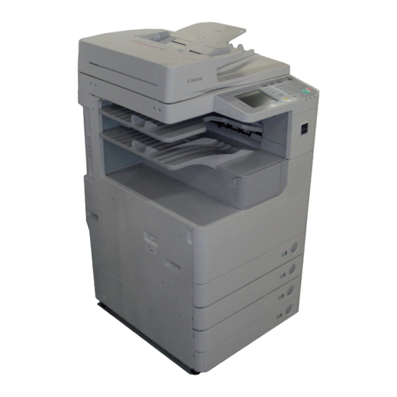
Product Overview > Name of Parts > External View Name of Parts Reader left cover [15] Rear left cover DADF (standard or optional) [16] Toner supply cover Reader front cover [17] Reader right cover External View Control panel [18] Platen glass Support cover [19] Reader rear cover... -
Page 24: Cross Sectional View
Product Overview > Name of Parts > Cross Sectional View 1-10 Cross Sectional View CCD unit [16] Registration roller ADF reading glass [17] Manual feed pickup roller Platen glass [18] Pickup roller (cassette Toner bottle [19] Vertical path roller 1 Drum unit [20] Feed roller (cassette 1) -
Page 25: Operation
Product Overview > Name of Parts > Operation > Description of Control Panel 1-11 Operation ■ Description of Control Panel ● Control Panel ■ Power Switch ● Types of power switch Control panel power switch [10] [11] Main power switch [12] [13] [14]... - Page 26 Product Overview > Name of Parts > Operation > Description of Control Panel 1-12 ● Main Menu ● Difference of Settings / Registration menu Functions Location imageRUNNER 2030/2025 Series imageRUNNER 2545/2535 Series Copy COPY key Common Settings Common Settings Send or Fax SEND key Control Panel Timer Settings...
-
Page 27: Technology
Technology ■ Basic Configuration ■ Original Expusure System ■ Controller System ■ Laser Exposure System ■ Image Formation System ■ Fixing System ■ Pickup Feed System ■ E-RDS Technology... -
Page 28: Functional Configuration
Technology > Basic Configuration > Functional Configuration > Basic sequence Basic Configuration ■ Basic sequence Functional Configuration ● Sequence at Power-On • Reader The machine may broadly be divided into the following functional system blocks; document exposure system block, controller system block, laser exposure system block, image STBY formation system block, fixing system block and pickup/feed system block. -
Page 29: Original Exposure System
Technology > Original Exposure System > Construction > Major Components Original Exposure System ■ Major Components Following shows major components of document exposure system. Construction PCB2 ■ Specifications/controls/functions The major specifications, controls and functions of the original exposure system are described below. - Page 30 Technology > Original Exposure System > Construction > Reader Relay PCB ■ Reader Relay PCB The function configuration of reader controller PCB is described below. J503 J504 J501 J512 J511 J505 J507 J502 J508 J506 J509 F-2-5 Jack No Description J501 Communication with main controller PCB J502...
-
Page 31: Basic Sequence
Technology > Original Exposure System > Basic Sequence > Basic Sequence at Start Key ON (ADF mode/1 original) Basic Sequence ■ Basic Sequence at Start Key ON (ADF mode/1 original) ■ Basic Sequence at Power-On Copy start Dust detection control In stream reading (Scanner motor) F F F... -
Page 32: Controls
Technology > Original Exposure System > Controls > Controlling the Scanner Drive System Controls ● Scanner Motor Control Scanner motor driver turns on/off the motor and controls its direction/speed of rotation ■ Controlling the Scanner Drive System according to the signals from CPU. ●... -
Page 33: Ccd
Technology > Original Exposure System > Controls > CCD 1) Forward movement when scanning an image ■ CCD CCD operation is controlled by the following sensors when scanning the image. ● Overview Original Start position Original The machine uses the CCD to expose and read an image and the image is read on a line-by- position trailing edge leading edge... - Page 34 Technology > Original Exposure System > Controls > CCD LED lens cover LED (light source) Lens Photoconductive body LED (light source) mirror No.4 mirror No.3 mirror No.2 mirror No.1 mirror No.5 Lens F-2-12 Red (R) line Green (G) line Blue (B) line Black &...
-
Page 35: Enlargement/Reduction
Technology > Original Exposure System > Controls > Detecting the Size of Originals ■ Enlargement/Reduction ■ Detecting the Size of Originals ● Magnifications in Main Scanning Direction ● Overview In book mode/ADF mode The machine identifies the original size by the combination of measurement result of reflection An image is read at 100% in main scanning direction. - Page 36 Technology > Original Exposure System > Controls > Detecting the Size of Originals 2-10 1. 2 points original detection at each detection position 2. Priority on the front sensor For each point of measurement in main scanning direction, the machine checks the When checking the measurements for main scanning direction, if the absence of an original presence/absence of an original with reference to the CCD output at 2 points near the point is indicated at the rear while the presence of an original is indicated at the front, the machine...
- Page 37 Technology > Original Exposure System > Controls > Detecting the Size of Originals 2-11 ● Detection Operation Overview 1) Standby state (The following is in case that the AB type, A4R size is set.) CCD unit: shading position 25° LED: OFF Original sensor: OFF 4) ADF fully closed (5 deg or less) F-2-20...
-
Page 38: Dirt Sensor Control
Technology > Original Exposure System > Controls > Dirt Sensor Control 2-12 ■ Dirt Sensor Control [Particulars of control] - At the end of a job (dust detection) ● Overview CCD checks the light reflected by the surface of the platen roller of the ADF at the read The machine changes the original read point or executes image correction depending on point to detect the presence/absence of dust. -
Page 39: Image Processing
Technology > Original Exposure System > Controls > Image Processing 2-13 - Between sheets ■ Image Processing The machine does not move CCD. ● Overview It reads the original using the position determined at the end or start of a job; however, The functions of image processing system’s PCB are described below. - Page 40 Technology > Original Exposure System > Controls > Image Processing 2-14 ● CCD Drive ● Shading Correction (Overview) The machine's CCD sensor is a 4-line linear image sensor consisting of 7500 pixels. After The output of the CCD is not necessarily even for the following factors even when the density completion of photoelectric conversion in the light-receiving block, the signals are output to of the original is uniform: the analog front end PCB unit on CCD PCB in parallel for each channel (R, G, B, B/W) of the...
-
Page 41: Service Operations
Technology > Original Exposure System > Service Operations > Service precautions 2-15 Service Operations ■ Action to take when replacing parts Part name Action Reference CCD unit • The values input of service data list (Service mode) Refer to page •... -
Page 42: Controller System
Technology > Controller System > Overview > Functional Configuration 2-16 Controller System Item Details Main controller PCB System control/memory control/printer unit output image processing control, reader unit input image processing, card Overview reader interface, image processing for FAX, USB extension hub interface Image memory Temporary saving of image data. - Page 43 Technology > Controller System > Overview > Functional Configuration 2-17 ● Main controller PCB Connector No. Function J8140 Serial interface connector J8141 Reader unit connector J8141 J8113 J8109 J8142 Laser scanner unit connector J8143 Laser scanner unit connector J8110 J8106 J8146 Pseudo CI connector J8147...
-
Page 44: Controls
Technology > Controller System > Controls > Construction of the Image Processing Module 2-18 Controls ■ Construction of the Image Processing Module ■ Flow of Image Data Other iR machine DC controller PCB Original Reader relay PCB Main controller PCB Reader unit input Copy image processing block... -
Page 45: Reader Unit Input Image Processing
Technology > Controller System > Controls > Compressio/ Extesion/ Editing Block 2-19 ■ Reader Unit Input Image Processing ■ Compressio/ Extesion/ Editing Block Main controller PCB Reader unit Reader image PDL image processing block processing block Main controller PCB SO-DIMM Enlargement/reduction Enlargement/ Compression... -
Page 46: Printer Unit Output Image Processing
Technology > Controller System > Controls > Flow of Image Data According to Copy Functions 2-20 ■ Printer unit Output Image Processing ■ Flow of Image Data According to Copy Functions Main controller PCB Reader unit Compression/expansion/editing block Main controller PCB Image processing block for reader unit Binary density conversion Enlargement/reduction... -
Page 47: Flow Of Image Data For The Send Function
Technology > Controller System > Controls > Flow of Image Data for the Fax Transmission 2-21 ■ Flow of Image Data for the SEND Function ■ Flow of Image Data for the Fax Transmission Reader unit Reader unit Main controller PCB Main controller PCB Image processing block for reader unit Image processing block for reader unit... -
Page 48: Flow Of Image Data For The Fax Reception Function
Technology > Controller System > Controls > Flow of Image Data for the PDL Function 2-22 ■ Flow of Image Data for the Fax Reception Function ■ Flow of Image Data for the PDL Function Ethernet Super G3 Fax Board Main controller PCB Main controller PCB Rendering processing block... -
Page 49: Software Counter
Technology > Controller System > Controls > Fan 2-23 ■ Software counter Name Function Error code E806-0001 Paper edge cooling fan (rear) Blows air to both ends of the fixing film to The timing at which the count is incremented differs depending on the following: FAN1 E805-0002 cool the sections where paper is not fed... - Page 50 Technology > Controller System > Controls > Fan 2-24 Overview Shutter (rear) When paper narrower than the A4 width (297 mm) is fed, the air outlet of the paper edge cooling fan (rear)/(front) opens to blow air to both ends of the fixing film, thus cooling the Film unit sections where paper is not fed.
-
Page 51: Power Supply
Technology > Controller System > Controls > Power supply 2-25 ■ Power supply ● Internal power supply +24VR USB HUB Kit Reader relay PCB CCD unit +24VU Interlock +24VR switch (SW2) +12VR Modem PCB Power +5VC +24VR +24VR supply PCB +5VR +12VC +24VR... - Page 52 Technology > Controller System > Controls > Power supply 2-26 ● Connection to Options ● Energy-saving Function Reader/ADF - 10 seconds after - Press of energy-saving key - Detection of off-hook completion of job or - Occurrence of job - Detection of off-hook network communication - Occurrence of service call - Occurrence of service call...
-
Page 53: Service Operations
Technology > Controller System > Service Operations > Service precautions 2-27 Service Operations ● Heater operating condition Cassette Reader Drum ■ Action to take when replacing parts heater heater heater Turning on the Standby mode Part name Action Reference environment heater switch Printing Secondary battery The secondary battery is powered even after the... -
Page 54: Laser Exposure System
Technology > Laser Exposure System > Construction > Main Configuration Parts 2-28 Laser Exposure System ■ Main Configuration Parts Construction ■ Specifications/Controls/Functions ● Laser light The number of laser light Output 10mW Wave length 775nm to 899nm (Infrared laser) T-2-16 ●... -
Page 55: Control System Configuration
Technology > Laser Exposure System > Construction > Control System Configuration 2-29 ■ Control System Configuration Signal name Function Image signal Controls for the laser exposure system are mainly performed by the DC controller PCB and DATA C+ C laser image data signal entry image PCB. -
Page 56: Basic Sequence
Technology > Laser Exposure System > Basic Sequence > Basic Sequence 2-30 Basic Sequence ■ Basic Sequence Initial rotation INTR):After the control panel key is ON, the machine starts the scanner motor and rotates the laser scanner motor until it reaches the number of target rotation while keepingall laser OFF. -
Page 57: Various Controls
Technology > Laser Exposure System > Various Controls > Controlling the Laser Activation Timing 2-31 Various Controls ■ Controlling the Laser Activation Timing ● Laser ON/OFF Control Laser ON/OFF control is dependent on the combination of the laser control signal (A/B laser: CNT1-0/1-1/1-2, C/D laser: CNT0-0/0-1/0-2) from the image PCB. - Page 58 Technology > Laser Exposure System > Various Controls > Controlling the Laser Activation Timing 2-32 MEMO: Regarding BD signal formation Not B laser but A laser only reaches BD sensor on BD PCB. BD signal is formed based on A laser light. J8143 J8142 BD_SYNCH...
-
Page 59: Controlling The Intensity Of Laser Light
Technology > Laser Exposure System > Various Controls > Controlling the Laser Shutter 2-33 ■ Controlling the Intensity of Laser Light ■ Controlling the Laser Shutter ● APC Control ● Laser Shutter Control The machine monitors the laser light that is emitted to the built-in photo diode of laser diode When the right door opens, laser shutter will be closed by laser shutter link that works in and adjusts the laser to appropriate intensity. -
Page 60: Image Formation System
Technology > Image Formation System > Basic Configuration > Specifications of Image Formation System 2-34 Image Formation System Basic Configuration ■ Specifications of Image Formation System Item Specifications/Mechanism/Method Photosensitive Material OPC high durability drum (E-drum) Drum diameter φ30 drum Cleaning method Cleaning blade Process speed 230mm/sec (at cassette pickup) -
Page 61: Major Components Of Image Formation System
Technology > Image Formation System > Basic Configuration > Major Components of Image Formation System 2-35 ■ Major Components of Image Formation System Name Function The major components of image formation system are described below. Toner cartridge Cartridge filled with the toner for supply Drum unit Unit consisting of the photosensitive drum, primary charging roller, etc. -
Page 62: Image Formation Process
Technology > Image Formation System > Basic Configuration > Image Formation Process 2-36 ■ Image Formation Process Image Formation Process Description The image formation system of the machine mainly consists of the photosensitive drum, [1] Primary charging block Charges the surface of the photosensitive drum to a primary charging roller, developing cylinder, transfer charging roller, static eliminator, and uniform negative potential. -
Page 63: Basic Sequence
Technology > Image Formation System > Basic Sequence > Sequence of Operation (last rotation) 2-37 Basic Sequence ■ Sequence of Operation (printing) The basic sequence is as follows. Registration Image write Registration Image formation sequence Image formation sequence Sheet-to-sheet ■ Sequence of Operation (initial rotation) (1st sheet) (2nd sheet and later) sequence... -
Page 64: Controls
Technology > Image Formation System > Controls > Drum Unit 2-38 Controls ● Primary Charging Bias Control The machine is directly charged by the charging roller. DC bias and AC bias that stabilized ■ Drum Unit the charge is applied to the primary charging roller. The drum unit mainly consists of the photosensitive drum, primary charging roller, brush roller, cleaning blade, and waste toner feed screw, and is driven by the main motor (M1). -
Page 65: Developing Unit
Technology > Image Formation System > Controls > Developing Unit 2-39 ■ Developing Unit ● Developing Bias Control The DC bias and AC bias are applied to the developing cylinder. The developing unit mainly consists of the developing cylinder, developing blade, toner agitation plate, and toner feed screw, and driven by the main motor (M1) and developing cylinder clutch (CL3). -
Page 66: Toner Container
Technology > Image Formation System > Controls > Toner Container 2-40 ■ Toner Container Sub hopper Toner feed screw Toner cartridge is filled with toner and supplies to the drum unit. Route of toner supply Toner cartridge Toner cartridge Toner feed screw Developing unit F-2-65 The toner in the toner cartridge is fed to the sub hopper and then to the developing unit by... -
Page 67: Transfer Unit
Technology > Image Formation System > Controls > Transfer Unit 2-41 ■ Transfer Unit ● Transfer Bias/Separation Static Eliminator Bias Control DC bias is applied to the transfer roller and static eliminator. The transfer unit mainly consists of the static eliminator and transfer roller which rotates in connection with the drum unit. -
Page 68: Waste Toner Box
Technology > Image Formation System > Controls > Waste Toner Box 2-42 ● Cleaning Bias Control ■ Waste Toner Box To return the toner adhered on the transfer roller to the photosensitive drum, negative voltage Residual toner adhered on the photosensitive drum without being transferred to a paper is is applied at the last rotation. -
Page 69: Work Of Service
Technology > Image Formation System > Work of Service > Points to Note about Service 2-43 Work of Service ■ When Replacing the Components None ■ Periodical Service None ■ Points to Note about Service None 2-43 Technology > Image Formation System > Work of Service > Points to Note about Service... -
Page 70: Fixing System
Technology > Fixing System > Overview > Specifications 2-44 Fixing System ■ Specifications Item Function/method Overview Fixing method On-demand fixing Fixing speed Cassette feeding 233mm/sec (1/1-high speed: 0.8% speed-up) ■ Features 230mm/sec (1/1-speed) 224mm/sec (1/1-slow speed: 3.1% speed-down) This machine introduces the on-demand fixing method. Manual feeding 139mm/sec (1/1-high speed: 0.8% speed-up) 137mm/sec (1/1-speed) -
Page 71: Major Parts Configuration
Technology > Fixing System > Overview > Major parts configuration 2-45 ■ Major parts configuration Part name Function / method Applying heat and pressure makes the toner image on paper Film unit Film unit fixed (fused). Pressure roller H1/H2 Fixing heater Ceramic heater Main thermistor To be in contact with the heater... -
Page 72: Controls
Technology > Fixing System > Controls > Fixing temperature control: overview 2-46 Controls ● Standby temperature control To preheat the fixing assembly to reduce time for starting print. ■ Fixing temperature control: overview • Flying start temperature control ● Print temperature control To increase temperature to meet the fixing target temperature and keep the target temperature during printing. -
Page 73: Standby Temperature Control
Technology > Fixing System > Controls > Print temperature control 2-47 ■ Standby temperature control ■ Print temperature control Max. 10 sec ● Startup (warm-up rotation) temperature control ● Flying start temperature control F-2-74 F-2-73 To increase fixing temperature to be ready for printing after receiving the print-start Purpose: command •... - Page 74 Technology > Fixing System > Controls > Print temperature control 2-48 C.Sheet-to-sheet distance temperature control Target temperature during printing To prevent the excessive temperature rise and to save the power consumption, the The control temperature is determined according to the fixing mode or to the fixing target temperature is set 5 deg C low (in case of plain paper *1) from the printing temperature at the start of warm-up control.
-
Page 75: Down Sequence Control
Technology > Fixing System > Controls > Down sequence control 2-49 ■ Down sequence control ● Down sequence when feeding small size paper Related Service Mode Offset of fixing control temperature (High and low of control temperature) Purpose: PRINT > SW To prevent temperature rise of non-feeding area in the case of continuous print of >... - Page 76 Technology > Fixing System > Controls > Down sequence control 2-50 Related Service Mode Fixing mode Step Free size Postcard Envelope LTRR Setting for down sequence start temperature when feeding small size paper EXE-R PRINT > SW > 64 Postcard <Setting value>...
-
Page 77: User Mode Related To Fixing Grade
Technology > Fixing System > Controls > User mode related to fixing grade 2-51 ● Down sequence when switching paper size ■ User mode related to fixing grade Purpose: The fixing grade is affected by some special modes in user mode which change the control This down sequence prevents temperature rise of non-feeding area: there can be temperature or productivity. -
Page 78: Fixing Pressure Roller Cleaning Sequence
Technology > Fixing System > Controls > Fixing film edge cooling control 2-52 ■ Fixing pressure roller cleaning sequence Temperature control/ User mode Summary Setting value productivity Purpose: Special Mode F The down sequence Image Priority Temperature difference time is reduced (Default) between the main and sub (To reduce the... -
Page 79: Paper Loop Amount Control Before Fixing
Technology > Fixing System > Controls > Paper loop amount control before fixing 2-53 ■ Paper loop amount control before fixing 4) Repeat steps 2) and 3). The fixing motor drive speed is increased by 0.8% Purpose: compared with the process speed when the trailing edge of paper reaches 65 mm To get a proper image by avoiding a shock when the trailing edge of paper comes out before coming out of the registration roller. -
Page 80: Protection Features
Technology > Fixing System > Controls > Protection features 2-54 ■ Protection features Error Code Description Clear E000 Fixing temperature abnormal rise 0001 The temperature detected by the main thermistor does not rise to the specified value during startup control. E001 Fixing unit temperature rise detection 0000... -
Page 81: Pickup Feed System
Technology > Pickup Feed System > Overview > Parts Configuration 2-55 Pickup Feed System ■ Parts Configuration ● Arrangement of Rollers Overview [20] [19] [18] [17] [16] ■ Specification Item Description Paper storage method Front loading method Pickup method Cassette Retard separation method Manual feed pickup tray Pad separation method... - Page 82 Technology > Pickup Feed System > Overview > Parts Configuration 2-56 ● Arrangement of Sensors Separation roller (cassette 1) Feed roller (cassette 1) Vertical path slave roller 1 Pickup roller (cassette 1) Manual feed pull-up roller Manual feed pickup roller Registration roller Transfer roller Duplexing/feeding roller 2...
-
Page 83: Diagram Of Paper Paths (W/ 2 Way Unit/ Inaner 2 Way Tray)
Technology > Pickup Feed System > Overview > Diagram of Paper Paths (w/ 2 Way Unit/ inaner 2 way tray) 2-57 ● Route of Drive ■ Diagram of Paper Paths (w/ 2 Way Unit/ inaner 2 way tray) Reversing point 2 Way Unit Delivery to tray 2 (option) -
Page 84: Diagram Of Paper Paths (W/O 2 Way Unit)
Technology > Pickup Feed System > Overview > Diagram of Paper Paths (w/o 2 Way Unit) 2-58 ■ Diagram of Paper Paths (w/o 2 Way Unit) Reversing point Delivery to tray 1 Pickup from manual feeder Pickup from cassette 1 F-2-82 2-58 Technology >... -
Page 85: Controls
Technology > Pickup Feed System > Controls > Cassette Pickup Assembly 2-59 Controls ■ Cassette Pickup Assembly ● Overview ■ Overview The paper inside the cassette is held up by the lifter plate. When pickup takes place, the pickup solenoid (SL1) is turned on, and the pickup roller is moved down. - Page 86 Technology > Pickup Feed System > Controls > Cassette Pickup Assembly 2-60 ● Paper Size Detection Cassette size switch (SW7) Paper size of the cassette can be automatically detected by adjusting the position of the guide plate. Rear Concavo-convex area of the cassette dial is switched when the guide plate is shifted and two detection Size Switches on a printer are switched.
- Page 87 Technology > Pickup Feed System > Controls > Cassette Pickup Assembly 2-61 Setting method when the size detection patterns are overlapped Width detection Length detection Width Length ASize should be found manually on the check screen for the combination of A5-Rand 257.0 182.0 STMT-R or the combination of B5-R and EXEC.
- Page 88 Technology > Pickup Feed System > Controls > Cassette Pickup Assembly 2-62 ● Paper level sensor If the paper is full Paper level in a cassette is detected with the sensor indicated below. Cassette 1 Paper Level Sensor A Paper Cassette 1 paper level sensor A Cassette 1 Paper Level Sensor B...
-
Page 89: Multi-Purpose Pickup Assembly
Technology > Pickup Feed System > Controls > Multi-Purpose Pickup Assembly 2-63 ■ Multi-Purpose Pickup Assembly Cassette 1 Cassette 1 Cassette 1 Paper level Display ● Overview paper level paper level paper sensor The paper in the tray of the manual feed pickup unit is forced against the manual feed pickup sensor A sensor B roller by the work of the pickup guide plate, and only a single sheet... -
Page 90: Fixing / Registration Assembly
Technology > Pickup Feed System > Controls > Duplex / Delivery Assembly 2-64 ■ Fixing / Registration Assembly ■ Duplex / Delivery Assembly ● Registration Control ● Duplex Feed Control The registration roller is driven by the main motor (M1). On this machine, the paper is revered outside the machine with using the reverse mouth. -
Page 91: Detecting Jams
Technology > Pickup Feed System > Controls > Detecting Jams 2-65 ■ Detecting Jams Jam Code Type Sensor Name Sensor ID 0101 Delay jam Cassette 1 pickup sensor 0105 Delay jam Pre-registration sensor Reverse mouth 2 0107 Delay jam Fixing outlet sensor 0108 Delay jam No. -
Page 92: Work Of Service
Technology > Pickup Feed System > Work of Service > Periodically Servicing 2-66 Work of Service ■ Periodical ServicePeriodical Service None ■ Consumables Item Parts No. Q'ty Life Remarks 1 Manual feed pickup roller FL3-1352 150,000 sheets 2 Manual feed separation pad FL3-3469 150,000 sheets... -
Page 93: Embedded Rds
Technology > Embedded RDS > Product Overview > Features and benefits 2-67 Embedded RDS ■ Features and benefits Since high confidentiality is required for the information shown above, it performs Product Overview communication between a device and a server using HTTPS/SOAP protocol. E-RDS embedded with a network module in advance can realize a front-end processing ■... -
Page 94: Network Settings
Technology > Embedded RDS > E-RDS Setup > Network settings 2-68 E-RDS Setup ■ Network settings Based on the results of the information obtained in (2) Advance preparations, make the iR To monitor a Copier/ MFP with e-Maintenance/ imageWARE Remote, the following settings device network related settings in accordance with the following procedures. - Page 95 Technology > Embedded RDS > E-RDS Setup > Network settings 2-69 c. Press [OK]. 1) Select Primary DNS Server, and then set the DNS server address. Example) 172. 001.016. 010 d. Press [Done]. ● DNS Settings e. Move on to Settings/ Registration > System Settings > Network Settings > TCP/IP Settings >...
- Page 96 Information item 3, described above. 1) Select [ON] in Use Proxy. j. Press [Done]. 2) Select Server Address, and then set the Proxy server address. Example) proxy.canon.com k. Press Reset button to quit the Setting/ Registration. 3) Enter Port Number. Example) 80 (1- 65535) l.
-
Page 97: Steps To E-Rds Settings
Technology > Embedded RDS > E-RDS Setup > Steps to E-RDS Settings 2-71 ■ Steps to E-RDS Settings The example of the service mode indication screen Locations of the user interface which performs E-RDS Settings from the servicemode is as follows. -
Page 98: Communication Log
Technology > Embedded RDS > E-RDS Setup > Initializing E-RDS settings 2-72 b. Select #E-RDS SWITCH、 and set value " 1" then touch [OK]. The communication with ■ Initializing E-RDS settings UGW is enabled by the above setting. It is possible to return E-RDS Settings to factory-shipments value. •... -
Page 99: Faq
Technology > Embedded RDS > FAQ 2-73 authentication with E-RDS can be done. Q1: Registration information of an E-RDS is once deleted from the UGW server, and is re- Q7: Can I turn the device power off during the e-Maintenance/ imageWARE Remote system registered after that. -
Page 100: Troubleshooting
Technology > Embedded RDS > Troubleshooting > Troubleshooting 2-74 Troubleshooting 3) Confirmation from another PC connected to same network. a) Request the user to ping the main unit from a PC connected to same network. ■ Troubleshooting Does the main unit respond? YES: Proceed to Step 4). -
Page 101: Error Code And Strings
Technology > Embedded RDS > Troubleshooting > Error code and strings 2-75 No.2 A communication test results NG! even if network setting is set properly. ■ Error code and strings Cause: No proper firmware has been installed, or E-RDS settings have not been completed. The error information appeared to a communication test log is as follows. - Page 102 Technology > Embedded RDS > Troubleshooting > Error code and strings 2-76 No. Code Error character Causes Remedy No. Code Error character Causes Remedy strings strings 8xxx Proxy address Could not connect to Check that the proxy server name is 14 8xxx Server response Displayed when...
- Page 103 Technology > Embedded RDS > Troubleshooting > Error code and strings 2-77 No. Code Error character Causes Remedy No. Code Error character Causes Remedy strings strings 19 8xxx Service not found There is a mistake in the Check that the value of Service mode 28 xxxx SUSPEND: Internal error occurred at...
-
Page 104: Com-Log Report
Technology > Embedded RDS > Service cautions 2-78 Service cautions ■ Com-Log Report The report output of the communication error logging information on five affairs can be carried After performing the following service activities it is necessary to perform Service mode out. -
Page 105: Periodical Service
Periodical Service ■ Consumable Parts and Cleaning Parts Periodical Service... - Page 106 Periodical Service > Consumable Parts and Cleaning Parts Consumable Parts and Cleaning Parts ●: Replaced (consumables) Δ: Cleaned System Items Parts No. Q'ty Life Interval Counter Remarks Reference iR2545/2535 Image Waste toner container FM3-9276 80,000 ● DRBL-1 WST-TNR Defined by 6% document p.
- Page 107 Periodical Service > Consumable Parts and Cleaning Parts Transfer roller Separation static eliminator Waste toner container Drum unit Developing assembly Manual feed pickup roller Manual feed separation pad Fixing unit Cassette pickup roller [10] Cassette feed roller [11] Cassette separation roller [12] Idler gear (for China) [12]...
-
Page 108: Cleaning Parts
Periodical Service > Cleaning Parts Cleaning Parts Fixing guide Transfer guide F-3-2 Periodical Service > Cleaning Parts... -
Page 109: Parts Replacement And Cleaning
Parts Replacement and Cleaning ■ List of Parts ■ External Covers ■ Main Units / Parts ■ Consumable Parts Requiring Periodic Replacement ■ PCBs ■ Solenoids ■ Motors ■ Fans ■ Switches ■ Clutches ■ Other Parts Replacement and Cleaning... -
Page 110: List Of Covers
Parts Replacement and Cleaning > List of Parts > List of Covers List of Parts Symbol Part name Part number Reference Reader Left Cover FC8-6197 p. 4-14 List of Covers DADF (Optional or Standard) Reader Front Cover FC9-0491 p. 4-14 Control Panel FM3-9354 (UL,AU) FM3-9358 (EUR) - Page 111 Parts Replacement and Cleaning > List of Parts > List of Covers Symbol Part name Part number Reference [16] [15] Reader Right Cover FC8-6198 p. 4-20 [15] [16] Platen Glass A SIZE: FL2-9839 p. 4-20 [17] A/INCH SIZE: FL2-9840 AB/INCH SIZE: FL2-9841 [17] Reader Rear Cover FC9-0492...
-
Page 112: List Of Main Units / Parts
Parts Replacement and Cleaning > List of Parts > List of Main Units / Parts List of Main Units / Parts Symbol Part name Part number Reference Right Cover Assembly FM3-9284 (With No.2 Deleivery Unit) p. 4-24 FM3-9380 (Without No.2 Deleivery Unit) Casstte Pickup Assembly FM3-9277 p. -
Page 113: List Of Pcbs
Parts Replacement and Cleaning > List of Parts > List of PCBs List of PCBs Symbol Part name Main unit Part number Reference PCB1 Main Controller PCB iR2535: FM4-6218 p. 4-43 PCB5d iR2545: FM4-6219" PCB2 Reader Relay PCB FM4-2859 p. 4-43 PCB3 Power Supply PCB 120V: FM4-4195... -
Page 114: List Of Solenoids
Parts Replacement and Cleaning > List of Parts > List of Solenoids List of Solenoids Symbol Part name Main unit Part number Reference Pickup Solenoid Casstte Pickup FK2-0408 Assembly Manual Feed Pickup Multi Pick-up Assembly FK2-1410 Solenoid Reversal Solenoid No.2 Deleivery FH6-5095 Assembly No. -
Page 115: List Of Sensors
Parts Replacement and Cleaning > List of Parts > List of Sensors List of Sensors F-4-6 F-4-7 Parts Replacement and Cleaning > List of Parts > List of Sensors... - Page 116 Parts Replacement and Cleaning > List of Parts > List of Sensors Symbol Part name Main unit Part number Reference Cassette 1 Pickup Sensor Casstte Pickup WG8-5836 Assembly Cassette 1 Paper Sensor Casstte Pickup WG8-5836 Assembly Cassette 1 Paper Level Sensor Cassette pick-up WG8-5836 assembly...
-
Page 117: List Of Motors
Parts Replacement and Cleaning > List of Parts > List of Motors List of Motors Symbol Part name Main unit Part number Reference Main Motor FK2-9141 p. 4-49 Fixing Motor FK2-9145 p. 4-49 Cassette 1 Pickup Motor FK2-7327 p. 4-50 Duplex Feed Motor FK2-9149 p. -
Page 118: List Of Fans
Parts Replacement and Cleaning > List of Parts > List of Fans 4-10 List of Fans Symbol Part name Main unit Part number Reference FAN1 Paper Edge Cooling Fan FK2-0360 p. 4-57 (Rear) FAN2 Paper Edge Cooling Fan FK2-0360 p. 4-57 (Front) FAN3 Exhaust Fan (Rear) -
Page 119: List Of Switches
Parts Replacement and Cleaning > List of Parts > List of Switches 4-11 List of Switches Symbol Part name Main unit Part number Reference Front Door Switch WC4-5242 p. 4-59 Enviorment Switch FM4-2876 Cassette Size Detection Switch WC2-5680 p. 4-60 Cassette Size Detection Switch WC2-5680 p. -
Page 120: List Of Clutches
Parts Replacement and Cleaning > List of Parts > List of Clutches 4-12 List of Clutches Symbol Part name Main unit Part number Reference Registration Clutch FK2-9154 p. 4-62 Manual Feed Pickup Clutch FK2-9154 p. 4-62 Developing Cylinder Clutch FK2-9154 p. -
Page 121: Other
Parts Replacement and Cleaning > List of Parts > Other 4-13 Other Symbol Part name Main unit Part number Reference Fixing Sub Thermistor (Rear) Fixing Assembly 120V: FM4-3364 230V: FM3-9303 Fixing Sub Thermistor (Front) Fixing Assembly Fixing Main Thermistor Fixing Assembly Fixing Heater 1 Fixing Assembly Fixing Heater 2... -
Page 122: External Covers
Parts Replacement and Cleaning > External Covers > Removing the Support Cover 4-14 External Covers Removing the Support Cover 1) Open the right cover. Removing the Reader Left Cover 2) Remove the support cover. • 2 screws (RS tightening; M3) 1) Remove the reader left cover. -
Page 123: Removing The Delivery Tray
Parts Replacement and Cleaning > External Covers > Removing the Front Cover 4-15 Removing the Delivery Tray Removing the Front Cover 1) Remove the support cover.(“Removing the Support Cover”(page 4-14).) 1)Open the front cover. 2) Remove the toner supply cover.(“Removing the Toner Supply Cover”(page 4-19).) 2)Remove the front cover belt. -
Page 124: Removing The Lower Left Cover
Parts Replacement and Cleaning > External Covers > Removing the Left Cover 4-16 Removing the Lower Left Cover Removing the Left Cover 1) Remove the cassette. 1) Draw out the cassette. 2) Remove the lower left cover. 2) Remove the lower left cover. (“Removing the Lower Left Cover”(page 4-16).) <For 550-sheet cassette model>... -
Page 125: Removing The Inside Base Cover
Parts Replacement and Cleaning > External Covers > Removing the Inside Base Cover 4-17 Removing the Inside Base Cover MEMO: When reassembling the left cover, insert the rod of the left cover switch into the main 1) Bend the left cover and remove the inside base cover. power switch securely. -
Page 126: Installing The Inside Base Cover
Parts Replacement and Cleaning > External Covers > Removing the Left Rear Cover 4-18 Installing the Inside Base Cover Removing the Left Rear Cover 1) Install the inside base cover. 1) Remove the face cover. • 1 screw (TP binding; M3) 2) Secure it with one screw. -
Page 127: Removing The Toner Supply Cover
Parts Replacement and Cleaning > External Covers > Removing the Toner Supply Cover 4-19 Removing the Toner Supply Cover 7) Open the toner supply cover. 8) Remove the toner supply cover. 1) Open the front cover. • 2 screws (RS tightening; M3) 2) Remove the support cover. -
Page 128: Removing The Reader Right Cover
Parts Replacement and Cleaning > External Covers > Removing the Reader Rear Cover 4-20 Removing the Reader Right Cover Removing the Platen Glass <For iR 2530/2525/2520> 1) Open the ADF or platen cover. 1) Remove the reader right cover by removing four screws, and then remove one screw from 2) Remove the glass retainer (right). -
Page 129: Removing The Rear Cover (Right)
Parts Replacement and Cleaning > External Covers > Removing the Rear Cover (Right) 4-21 Removing the Rear Cover (Right) 3) Remove the ADF power cable. • 3 connectors 1) Remove the power supply retaining cover. • 1 screw (RS tightening; M3) •... -
Page 130: Removing The Rear Cover (Left)
Parts Replacement and Cleaning > External Covers > Removing the Lower Rear Cover 4-22 Removing the Rear Cover (Left) Removing the Rear Right Cover (Lower) 1) Remove the rear cover (right). (“Removing the Rear Cover (Right)”(page 4-21).) 1) Raise the handle at the rear right, and then remove one screw. 2) Remove the rear cover (left). -
Page 131: Removing The Cassette 2 Rear Cover
Parts Replacement and Cleaning > External Covers > Removing the Cassette 2 Rear Cover 4-23 2) Disconnect all connectors (only for the machine with an optional cassette). F-4-43 3) Remove the lower rear cover. • 1 screw (RS tightening; M3) •... -
Page 132: Main Units/Parts
Parts Replacement and Cleaning > Main Units/Parts > Removing the Right Cover Assembly 4-24 Main Units/Parts 6) Remove the belt. • 2 screws Removing the Right Cover Assembly 1) Remove the reader right cover. (“Removing the Reader Right Cover”(page 4-20)..) 2) Remove the reader rear cover. - Page 133 Parts Replacement and Cleaning > Main Units/Parts > Removing the Right Cover Assembly 4-25 7) Remove the connection cable. 10)Remove the right cover assembly. 2 connectors (The machine without the No.2 delivery unit does not have the upper connector.) CAUTION: Be sure to disconnect the upper connector after releasing the harness from the clamp to prevent breaking of wire 8) Remove one screw.
-
Page 134: Removing The Cassette Pickup Assembly
Parts Replacement and Cleaning > Main Units/Parts > Removing the Cassette Pickup Assembly 4-26 Removing the Cassette Pickup Assembly 7) Remove the link between the right cover and pickup assembly. 8) Remove the cassette pickup assembly. 1) Draw out the cassette. •... -
Page 135: Removing The Laser Scanner Unit
Parts Replacement and Cleaning > Main Units/Parts > Removing the Laser Scanner Unit 4-27 Removing the Laser Scanner Unit 1) Remove the inside base cover.(“Removing the Inside Base Cover”(page 4-17).) 2) Remove the left cover.(“Removing the Left Cover”(page 4-16).) 3) Remove the scanner retaining plate. 1 screw F-4-52 4) Remove the laser scanner unit. -
Page 136: Action To Take After Replacing The Laser Scanner Unit
Parts Replacement and Cleaning > Main Units/Parts > Removing the Toner Supply Assembly 4-28 Removing the Toner Supply Assembly ■ Action to Take after Replacing the Laser Scanner Unit When replacing the laser unit, enter the values recorded on the label affixed to the laser unit 1) Remove the inside base cover.(“Removing the Inside Base Cover”(page 4-17).) -
Page 137: Action To Take After Replacement
Parts Replacement and Cleaning > Main Units/Parts > Removing the Toner Supply Assembly > Action to Take after Replacement 4-29 ■ Action to Take after Replacement MEMO: The service parts for toner supply unit do not come with a bottle ring. Remove the bottle ring from the old toner supply unit and attach it to the new one. -
Page 138: Removing The Ccd Unit
Parts Replacement and Cleaning > Main Units/Parts > Removing the CCD Unit 4-30 Removing the CCD Unit 3)Remove the bottle ring. 1) When replacing with a new CCD unit, enter the following service mode to output a service data list. REPORT>... - Page 139 Parts Replacement and Cleaning > Main Units/Parts > Removing the CCD Unit 4-31 8) Remove the shaft. F-4-63 CAUTION: F-4-61 Do not touch the LED on the CCD unit. 9) Loosen the screw, and then loosen the belt. 11)Remove the CCD unit. •...
-
Page 140: Action To Take After Replacing The Ccd Unit
Parts Replacement and Cleaning > Main Units/Parts > Removing the CCD Unit > Action to Take after Replacing the CCD Unit 4-32 ■ Action to Take after Replacing the CCD Unit 6-4) Place a sheet of paper that the user usually uses on the DF, enter the service mode, and then select SCAN >... -
Page 141: Removing The Platen Glass
Parts Replacement and Cleaning > Main Units/Parts > Removing the Platen Glass > Action to Take after Replacing the Platen Glass 4-33 Removing the Platen Glass 1) Open the platen cover (platen board cover/ADF). 2) Remove the glass retainer.(“Removing the Platen Glass”(page 4-20)..) •... -
Page 142: Removing The Adf Scan Glass
Parts Replacement and Cleaning > Main Units/Parts > Removing the ADF Scan Glass > Action to Take after Replacing the ADF Scan Glass 4-34 glass for stream reading.)(Read both sides of the chart.) CAUTION: 3) Place a sheet of paper that the user usually uses on the platen glass, enter the service •... -
Page 143: Removing The Control Panel Assembly
Parts Replacement and Cleaning > Main Units/Parts > Removing the Multi Pickup Assembly 4-35 Removing the Multi Pickup Assembly 3) Place a sheet of paper that the user usually uses on the platen glass, enter the service mode, and then select SCAN > READER > FUNCTION > CCD > DFWLVL3. 1) Open the right cover assembly. - Page 144 Parts Replacement and Cleaning > Main Units/Parts > Removing the Multi Pickup Assembly 4-36 3) Remove the connector cover. 4) Remove the multi pickup assembly. • 2 screws • 4 screws 3) Remove the harness. F-4-73 • 1 connector F-4-75 •...
-
Page 145: Consumable Parts Requiring Periodic Replacement
Parts Replacement and Cleaning > Consumable Parts Requiring Periodic Replacement > Removing the Waste Toner Container 4-37 Consumable Parts Requiring Periodic Replacement Removing the Separation Static Charge Eliminator 1) Open the right cover. Removing the Transfer Roller 2) Remove the separation static charge eliminator. - 1 claw 1) Open the right cover. -
Page 146: Removing The Drum Unit
Parts Replacement and Cleaning > Consumable Parts Requiring Periodic Replacement > Removing the Drum Unit 4-38 Removing the Drum Unit 3) Remove the waste toner container. 1) Open the right cover. 2) Open the front cover. 3) Remove the waste toner container. (“Removing the Waste Toner Container”(page 4-37). -
Page 147: Removing The Developing Assembly
Parts Replacement and Cleaning > Consumable Parts Requiring Periodic Replacement > Removing the Manual Feed Pickup Roller 4-39 7) Pull out the drum unit slightly upward. CAUTION: When installing the toner supply unit, insert a guide of the developing unit to the ditch of the host machine. -
Page 148: Removing The Manual Feed Separation Pad
Parts Replacement and Cleaning > Consumable Parts Requiring Periodic Replacement > Removing the Manual Feed Separation Pad 4-40 Removing the Manual Feed Separation Pad 2) Release the claws, and then slide the bearing (front). 3) Remove the manual feed pickup roller. 1) Remove the manual feed pickup roller. -
Page 149: Removing The Fixing Unit
Parts Replacement and Cleaning > Consumable Parts Requiring Periodic Replacement > Removing the Cassette Feed Roller 4-41 Removing the Fixing Unit Removing the Cassette Pickup Roller 1) Open the right cover 1) Draw out the cassette from the main unit. 2) Remove the fixing unit. -
Page 150: Removing The Cassette Separation Roller
Parts Replacement and Cleaning > Consumable Parts Requiring Periodic Replacement > Removing the Idler Gear (For China Only) 4-42 Removing the Cassette Separation Roller 1) Draw out the cassette from the main unit. 2) Open the right cover. 3) Remove the cassette separation roller. - 1 claw F-4-97 F-4-96... -
Page 151: Pcb
Parts Replacement and Cleaning > PCB > Removing the Reader Relay PCB > Replacement Procedure 4-43 Removing the Reader Relay PCB ■ Replacement Procedure Removing the Main Controller PCB 1) Remove the reader rear cover. (“Removing the Reader Rear Cover”(page 4-20).) ■... -
Page 152: Removing The Power Supply Pcb
Parts Replacement and Cleaning > PCB > Removing the DC Controller PCB > Action to Take after Replacement/RAM Clearing 4-44 Removing the Power Supply PCB Removing the DC Controller PCB ■ Replacement Procedure ■ Before Replacement/RAM Clearing 1) Remove the inside base cover.(“Removing the Inside Base Cover”(page 4-17).) Print the service data list in the service mode. -
Page 153: Removing The Hvt Pcb
Parts Replacement and Cleaning > PCB > Removing the Option Power Supply PCB > Replacement Procedure 4-45 Removing the HVT PCB Removing the Option Power Supply PCB ■ Replacement Procedure ■ Replacement Procedure 1) Remove the rear cover (right).(“Removing the Rear Cover (Right)”(page 4-21).) 1) Remove the rear cover (right).(“Removing the Rear Cover (Right)”(page... -
Page 154: Removing The Heater Pcb
Parts Replacement and Cleaning > PCB > Removing the Heater PCB > Replacement Procedure 4-46 Removing the Heater PCB 5) Disconnect all connectors on the option power supply PCB. 6) Remove the option power supply PCB. ■ Replacement Procedure - 2 screws 1) Remove the rear cover (right).(“Removing the Rear Cover (Right)”(page 4-21).) -
Page 155: Removing The Ram Pcb
Parts Replacement and Cleaning > PCB > Removing the RAM PCB > Replacement Procedure 4-47 Removing the RAM PCB 3) For the model with a FAX and SEND function, press the SW3 on the main controller to check that LED10 goes out. (Secondary power cutoff) ■... - Page 156 Parts Replacement and Cleaning > PCB > Removing the RAM PCB > Replacement Procedure 4-48 4) Remove the RAM PCB. (Release the hook.) F-4-108 4-48 Parts Replacement and Cleaning > PCB > Removing the RAM PCB > Replacement Procedure...
-
Page 157: Removing The Main Motor (M1)
Parts Replacement and Cleaning > PCB > Removing the Fixing Motor (M2) > Replacement Procedure 4-49 Removing the Main Motor (M1) Removing the Fixing Motor (M2) ■ Replacement Procedure ■ Replacement Procedure 1) Remove the rear cover (right).(“Removing the Rear Cover (Right)”(page 4-21).) 1) Remove the rear cover (right).(“Removing the Rear Cover (Right)”(page... -
Page 158: Removing The Cassette 1 Pickup Motor (M3)
Parts Replacement and Cleaning > PCB > Removing the Cassette 1 Pickup Motor (M3) > Replacement Procedure 4-50 5) Disconnect all connectors on the DC controller PCB. 7) Remove the fixing motor. 6) Remove the DC controller PCB assembly. - 1 connector - 3 screws - 4 screws F-4-112... -
Page 159: Removing The Duplex Feed Motor (M4)
Parts Replacement and Cleaning > PCB > Removing the Shutter Motor (M8) > Replacement Procedure 4-51 Removing the Duplex Feed Motor (M4) Removing the Shutter Motor (M8) ■ Replacement Procedure ■ Replacement Procedure 1) Remove the rear cover (right).(“Removing the Rear Cover (Right)”(page 4-21).) 1) Remove the fixing assembly.(“Removing the Fixing Unit”(page... - Page 160 Parts Replacement and Cleaning > PCB > Removing the Shutter Motor (M8) > Replacement Procedure 4-52 - 2 connectors 5) Remove the rack (right). - 2 claws 6) Remove the shutter motor. F-4-119 - 2 screws 4) Remove the gear. F-4-117 -1 claw CAUTION:...
-
Page 161: Removing The No.1 Delivery Motor (M9)
Parts Replacement and Cleaning > PCB > Removing the No.1 Delivery Motor (M9) > Replacement Procedure 4-53 Removing the No.1 Delivery Motor (M9) 8) Remove the No.2 deleivery unit. - 2 connectors ■ Replacement Procedure 1) Remove the inside base cover.(“Removing the Inside Base Cover”(page 4-17).) 2) Remove the toner supply... - Page 162 Parts Replacement and Cleaning > PCB > Removing the No.1 Delivery Motor (M9) > Replacement Procedure 4-54 9) Remove the deleivery drive inner cover. Hole - 2 claws Boss 11) Remove the DC controller PCB. F-4-126 10) Remove the No.1 deleivery unit. F-4-124 - 1 screw F-4-125...
- Page 163 Parts Replacement and Cleaning > PCB > Removing the No.1 Delivery Motor (M9) > Replacement Procedure 4-55 12) Remove the No.1 deleivery drive unit. 13) Remove the No.1 delivery motor. - 3 screws - 1 connector - 2 screws F-4-128 F-4-127 4-55 Parts Replacement and Cleaning >...
-
Page 164: Removing The Reversal Motor (M10)
Parts Replacement and Cleaning > PCB > Removing the Scanner Motor (M21) > Replacement Procedure 4-56 Removing the Reversal Motor (M10) Removing the Scanner Motor (M21) ■ Replacement Procedure ■ Replacement Procedure 1) Remove the No.2 deleivery unit.(“8) Remove the No.2 deleivery unit.”(page 4-53).) 1) Remove the ADF communication cable (only machines with ADF installed). -
Page 165: Removing The Paper Edge Cooling Fan (Rear) (Fan1)
Parts Replacement and Cleaning > PCB > Removing the Paper Edge Cooling Fan (Front) (FAN2) > Replacement Procedure 4-57 Removing the Paper Edge Cooling Fan (Rear) (FAN1) Removing the Paper Edge Cooling Fan (Front) (FAN2) ■ Replacement Procedure ■ Replacement Procedure 1) Remove the inside base cover.(“Removing the Inside Base Cover”(page 4-17).) -
Page 166: Removing The Power Supply Cooling Fan (Fan6)
Parts Replacement and Cleaning > PCB > Removing the Power Supply Cooling Fan (FAN6) > Replacement Procedure 4-58 Removing the Power Supply Cooling Fan (FAN6) ■ Replacement Procedure 1) Remove the rear cover (right).(“Removing the Reader Rear Cover”(page 4-20).) 2) Remove the lower rear cover.(“Removing the Lower Rear Cover”(page 4-22).) 3) If equipped with the heater PCB, remove the heater... -
Page 167: Removing The Front Door Switch (Sw2)
Parts Replacement and Cleaning > PCB > Removing the Front Door Switch (SW2) > Replacement Procedure 4-59 Removing the Front Door Switch (SW2) ■ Replacement Procedure NOTE: When reinstalling the box tray shaft, fit the insertion part into the hole. 1) Remove the support cover.(“Removing the Support Cover”(page 4-14).) -
Page 168: Removing The Cassette Size Detection Switch (Sw6/Sw7)
Parts Replacement and Cleaning > PCB > Removing the Cassette Size Detection Switch (SW6/SW7) > Replacement Procedure 4-60 Removing the Cassette Size Detection Switch (SW6/ 7) Remove the internal cover (right upper). - 2 screws SW7) ■ Replacement Procedure 1) Remove the cassette. 2) Remove the lower rear cover.(“Removing the Lower Rear Cover”(page 4-22).) - Page 169 Parts Replacement and Cleaning > PCB > Removing the Cassette Size Detection Switch (SW6/SW7) > Replacement Procedure 4-61 5) Remove the cassette size detection switch. - 1 connector - 1 screw - 2 claws F-4-142 4-61 Parts Replacement and Cleaning > PCB > Removing the Cassette Size Detection Switch (SW6/SW7) > Replacement Procedure...
-
Page 170: Removing The Clutch (Cl1/Cl2/Cl3)
Parts Replacement and Cleaning > PCB > Removing the Clutch (CL1/CL2/CL3) > Replacement Procedure 4-62 Removing the Clutch (CL1/CL2/CL3) 5) Remove the clutch. - 1 connector ■ Replacement Procedure - 1 resin E-ring 1) Remove the rear cover (right).(“Removing the Rear Cover (Right)”(page 4-21).) 2) Remove the rear cover (left).(“Removing the Rear Cover (Left)”(page... -
Page 171: Other
Parts Replacement and Cleaning > OTHER > Removing the Fixing Film Unit > Replacement Procedure 4-63 OTHER CAUTION: When installing the left side plate, install it to engage the teeth with the locking lever at Removing the Fixing Film Unit the position shown in the figure. - Page 172 Parts Replacement and Cleaning > OTHER > Removing the Fixing Film Unit > Replacement Procedure 4-64 6) Remove the cable guide. 8) Turn the pressure unit and release the pressure unit. - 1 boss 9) Remove the 2 screws. F-4-151 7) Remove the fixing film cover.
- Page 173 Parts Replacement and Cleaning > OTHER > Removing the Fixing Film Unit > Replacement Procedure 4-65 10) Turn the pressure unit and release the pressure unit. 12) Remove the conductive plate. - 1 screw - 1 claw 11) Remove the connector cover. F-4-153 - 1 claw 13) Remove the fixing cable guide (right).
- Page 174 Parts Replacement and Cleaning > OTHER > Removing the Fixing Film Unit > Replacement Procedure 4-66 14) Remove the stopper. 16) Remove the gear. - 1 E-ring 15) Remove the heater contact connector. F-4-157 17) Remove the relay connector from the cable guide. F-4-159 F-4-158 F-4-160...
- Page 175 Parts Replacement and Cleaning > OTHER > Removing the Fixing Film Unit > Replacement Procedure 4-67 18) Remove the fixing cable guide (left). 21) Remove the fixing film unit. - 1 screw - 1 connector 19) Remove the stopper. F-4-161 F-4-164 20) Remove the heater contact connector.
-
Page 176: Removing The Pressure Roller
Parts Replacement and Cleaning > OTHER > Removing the Pressure Roller > Replacement Procedure 4-68 Removing the Pressure Roller 3) Remove the pressure roller. - 2 bushes ■ Replacement Procedure - 2 bearings 1) Remove the fixing film unit.(“Removing the Fixing Film Unit”(page 4-63).) 2) Remove the guide. -
Page 177: Adjustment
Adjustment ■ Outline ■ Adjustment when replacing parts ■ Image position adjustment Adjustment... -
Page 178: Adjustment When Replacing Parts
Adjustment > Outline > Image position adjustment Outline Category Item Reference Left Image MarginSingle-sided copy: 2.5 ± 1.5 (mm) “Left Image Double-sided copy: 2.5 ± 2.0 (mm) Margin”(page 5-6). Adjustment when replacing parts 2.5+/-1.5mm (2nd side of double-sided copy: This section describes adjustment required in field service works when replacing parts. 2.5+/-2.0mm) The parts are classified by function into the following 3 blocks. -
Page 179: Scanning System
Adjustment > Adjustment when replacing parts > Scanning System > Action to Take after Replacing the CCD Unit Adjustment when replacing parts glass for stream reading.)(Read both sides of the chart.) 6-3) Place a sheet of paper that the user usually uses on the platen glass, enter the service mode, and then select SCAN >... -
Page 180: Action To Take After Replacing The Platen Glass
Adjustment > Adjustment when replacing parts > Scanning System > Action to Take after Replacing the ADF Scan Glass ■ Action to Take after Replacing the Platen Glass ■ Action to Take after Replacing the ADF Scan Glass 1.Enter the service mode, and then select the following: CAUTION: SCAN >... -
Page 181: Controller System
Adjustment > Adjustment when replacing parts > Laser Exposure System > Action to Take after Replacing the Laser Scanner Unit Controller System ■ Action to Take after Replacing the RAM ■ Action to Take after Replacing theMain Controller PCB CAUTION: After replacing the main controller PCB with a new one, take the following action: The ADRAM is powered from the secondary battery unit to back up the image memory •... -
Page 182: Image Position Adjustment
Adjustment > Image position adjustment > Leading Edge Non-Image Width Image position adjustment Left Image Margin Service mode> PRINT> PRINT NUMERIC> 056 Copy 10 sheets from each pickup position to check that the image margin and non-image area is within the standard. Image left edge •... -
Page 183: Left Non-Image Width
Adjustment > Image position adjustment > Left Non-Image Width Left Non-Image Width Service mode> SCAN> READER> ADJUST> ADJ-XY> ADJ-Y Image edge Decrease the value. Increase the value. (a decrease of '10' will (an increase of '10' will decrease the non-image increase the non-image width by 1 mm) width by 1 mm) -
Page 184: Troubleshooting
Troubleshooting ■ Initial Check ■ Test Print ■ Troubleshooting items ■ Upgrading Targets and Procedure Troubleshooting... -
Page 185: Initial Check Items List
The machine is not near a source of fi re or dust. Check if using Canon recommended paper/transparency makes it The site is not subject to ammonium gas. better or not. -
Page 186: Test Print
Test Print Overview This machine have the following test print TYPE and you can judge the image failure that is checked as “Yes” in the following image check items with each test print. If the image failure occurred on normal output does not reappear on the test print, it may be caused by the PDL input or reader side. Select the test print TYPE TYPE Pattern Items... -
Page 187: Troubleshooting Items
Troubleshooting items [Cause] Fixing assembly: Toner came off the paper sticks to the pressure roller, and then the toner sticks to the reverse side of the paper. Troubleshooting items list Transfer roller: Toner remained on the drum that had stopped at occurrence of a jam. During the recovery operation performed later, the toner sticks to the transfer roller. -
Page 188: Image Transfer Wrong/Text Void
Fixing inlet guide: The leading or trailing edge of paper touches the toner stuck to the fixing USER MODE> Adjustment/ Cleaning> Special Mode M> Low or High inlet guide. ■ Image Deletion/Blur/Dew Condensation [Occurrence condition] When halftone or solid-black images are printed in succession [Remedy] Using lens-cleaning paper or the like, clean the guide stained with toner. -
Page 189: Too Large Curl
■ Too Large Curl ■ Paper Jam due to Solid Image Printed on Paper with Small Leading-Edge Margin (1-4 mm) [Occurrence area] Fixing assembly [Occurrence area] Fixing assembly [Cause] The water content on the front surface of paper becomes different from that on the reverse [Cause] side of paper, making the curl larger. -
Page 190: Abnormal Noise During Multi-Feed Peration
■ Abnormal Noise During Multi-Feed Peration Escape hole [Occurrence area] Gear of right cover unit [Cause] When the right cover unit is closed, the belt cannot enter the clearance groove depending on the lower belt securing position and therefore the belt is Z-folded. As a result, the right cover unit is pushed out and consequently the gear on the right cover unit side meshes with the gear on the host machine side loosely, generating abnormal noise. -
Page 191: Upgrading Targets And Procedure
Upgrading Targets and Procedure Host machine Target Category Target system File type Remarks software Outline Main iR2545/iR2535 Boot USTUPDATE_iR2545_35_ There are two types BOOT_vXXXX of main controllers. controller There are two methods to upgrade the system software. Program USTUPDATE_iR2545_35_ Note: When upgrading bootable_lang_WLaaXXXX two types of firmware, 1. -
Page 192: Procedure
Procedure 6) Click [Next] following the instruction shown on the screen. MEMO: The procedure for upgrading Boot is described below as a typical example. Use the same procedure for other firmware. 1) Turn ON the power switch of the PC and start up the UST. 2) When the power switch is turned ON, a Found New Hardware Wizard appears. - Page 193 6-10 8) Click [Next] following the instruction shown on the screen. 9) Click [Start] following the instruction shown on the screen. F-6-9 F-6-11 10) Click [Yes] following the instruction shown on the screen. MEMO: If firmware for a wrong model is selected, “Specify by printer name” is not displayed. F-6-12 11) The following screen appears.
- Page 194 6-11 CAUTION: Do Not Turn off the Power during Download/Write Operation in progress Do not turn OFF the power while the system software is being downloaded or written. The machine may fail to start when the power is turned ON. 12) When upgrade is complete, the following screen appears.
-
Page 195: Error Code Overview
Error Code ■ Overview ■ Error Code ■ Jam Code ■ Alarm Code... -
Page 196: Outline
Overview Outline This chapter describes various codes which are displayed when a failure occurs on the product. These are classified into 3 codes as follows. Code type Explanation Reference Error code This code is displayed when an error occurs on the machine. Refer to page 7-3 Jam code... -
Page 197: Error Code
Error Code Ecode Detail Item Description Code E002 0000 Title Fixing unit temperature insufficient rise Error Code Details Description 1.The reading of the main thermistor is less than 115 deg C continuously for 400 msec 1.3 sec after it has indicated 100 deg C. - Page 198 Ecode Detail Item Description Ecode Detail Item Description Code Code E014 0001 Title Unstable rotation of the Fixing Motor (M2) E024 0001 Title The Developing Assembly Toner Sensor (TS1) is disconnected. Description Detection is executed every 100 msec after the start of motor rotation;...
- Page 199 Ecode Detail Item Description Ecode Detail Item Description Code Code E110 0002 Title Failure of the Scanner Motor (M21) E225 0000 Title The light intensity of the CCD is faulty. Description The speed lock signal indicates a deviation 10 times in Description The light intensity of the CCD during shading is under the sequence at intervals of 100 msec after the signal has...
- Page 200 Ecode Detail Item Description Ecode Detail Item Description Code Code E261 0000 Title Error in Zero Cross E531 8001 Title Stapler Motor (M10) error Description Zero Cross failed to be detected for 500ms or more while the Description The stapler does not leave the staple home position when the relay was ON.
- Page 201 Ecode Detail Item Description Ecode Detail Item Description Code Code E542 0005 Title Additional Tray Lift Motor (M12) closing detect switch error E575 0002 Title Gripper Unit Move Motor (M2) error Description The FG input cannot be detected when the Additional Tray Description The gripper unit does not return to the gripper unit home Lift Motor (M12) has been driven for 0.1 second.
- Page 202 Ecode Detail Item Description Ecode Detail Item Description Code Code E719 0002 Title Erroneous communication with Coin Vendor (serial E805 0000 Title Failure of the Exhaust Fan (Rear) (FAN3) communication) Description "When lock signal is detected for 5 sec while the Exhaust Fan Description (Rear) (FAN3) is stopped.
-
Page 203: Fax Error Code
FAX Error Code ■ Service Error Code ● Service Error Code ■ Outline Tx/Rx Description ● Error Code Outline ##0100 [Tx] At time of transmission, the procedural signal has been transmitted more than An error code is used to indicate a fault in a machine, and is indicated in the machine's LCD specified. - Page 204 7-10 Tx/Rx Description Tx/Rx Description ##0671 [Rx] At time of V.8 arrival, procedure fails to move to phase 2 after detection of CM ##0769 [Tx] At time of ECM transmission, the procedural signal has been transmitted more signal from caller, causing T1 time-out and releasing line. than specified after transmission of PPS-EOP, or T5 time-out (60 sec) has occurred.
- Page 205 7-11 7-11...
-
Page 206: Jam Code
7-12 Jam Code ACC ID Jam Code Type Sensor Name Sensor ID 0101 Delay jam Cassette 1 pickup sensor 0102 Delay jam Cassette 2 pickup sensor Main Unit 0103 Delay jam Cassette 3 pickup sensor 0104 Delay jam Cassette 4 pickup sensor 0105 Delay jam Pre-registration sensor... -
Page 207: Dadf-Aa1
7-13 DADF-AA1 ACC ID Jam Code Type Sensor Name Sensor ID FF0D Unknown jam FF91 Unknown jam SR11 FFF1 Unknown jam T-7-5 F-7-2 7-13... -
Page 208: Inner Finisher-B1
7-14 Inner Finisher-B1 ACC ID Jam Code Type Sensor Name Sensor ID 0003 Delay jam Registration sensor 0004 Stationary jam Registration sensor 0005 Delay jam Read sensor 0006 Stationary jam Read sensor 0007 Delay jam Delivery reversal sensor 0008 Stationary jam Delivery reversal sensor 0044 Stationary jam... - Page 209 7-15 ACC ID Jam Code Type Sensor Name Sensor ID 1001 Delay jam Entrance sensor 1101 Stationary jam Entrance sensor 1102 Stationary jam Processing tray sensor 1300 Power-on jam Entrance sensor, Processing tray S1, S6 sensor 1400 Door open jam Front cover switch 1500 STP jam...
-
Page 210: Alarm Code
7-16 Alarm Code Alarm Code Details Alarm Code Title A. Movement /B. Cause /C. Measures 0001 Repair Request (Corrupt Image) 0002 Repair Request (Paper Jam) 0003 Repair Request (Corrupt Image/Paper Jam) 0004 Repair Request (Other Problems) 0005 Repair Request (Corrupt Image/Other Problems) 0006 Repair Request (Paper... -
Page 211: Service Mode
Service Mode ■ Outline ■ Details of Service Mode... -
Page 212: Outline Of Service Mode
Outline #CODEC This is a setting items related to CODEC. Outline of Service Mode #SYSTEM The items that follow may be checked/set using the machine's service mode, which is This is a setting items related to SYSTEM. designed the way the service mode used in fax machines is designed in terms of contents and operation. -
Page 213: Using The Mode
Using the Mode Setting of Bit Switch ■ Outline <Operation at the time of Bit SW> <Operation at the time of Parameter> Bit Switch Composition 1) Selecting Service Mode 1) Selecting Service Mode The items registered and set by each of these switches comprise 8-bit switches. The figure below shows which numbers are assigned to which bits. -
Page 214: Back-Up
Back-Up Service Label At time of shipment from the factory, all machines are adjusted individually, and adjustment The item of service kabel is described below. values are recorded in their respective service labels. In this machine, the output of the service label does not support. If you have replaced the CCD/CIS unit or the DC controller PCB, or if you have initialized the RAM, the adjustment values will return to their default settings. -
Page 215: Details Of Service Mode
Details of Service Mode ■ Details ● SSSW-SW01 #SSSW List of Functions Function ■ SSSW Composition service error code output not output not used NOTE: not used This document describes the default settings for the system for USA. not used The default settings used in the service mode vary depending on the shipping not used destination and model. - Page 216 ● SSSW-SW03 MEMO: List of Functions Any of the following error code may be indicated because of an echo at time of reception Function ##0005, ##0101, ##0106, ##0107, ##0114, ##0200, ##0201, ##0790 TCF criteria Loose Normal Echo protect tone for high-speed transmission Transmitted Not transmitted not used ●...
- Page 217 Use it specify whether or not to transmit bit 33 and thereafter for the DIS signal. Detailed Discussions of Bit 5 If ‘prohibit’ is selected, Super Fine reception from a non-Canon machine can no longer be In the countries that need approval of CI signal frequency check, no checking on frequency used.
- Page 218 ● SSSW-SW06 Time-Out Length for Transmission/reception List of Functions Bit7 Bit6 Bit5 Bit4 Bit3 Bit2 Bit1 Bit0 Function 8min. not used 16min. not used 32min. not used 64min. FAX stamp display setting Displayed Not displayed original read width T-8-9 not used Time-Out Length for Transmission (text mode) not used Bit7...
- Page 219 Function Function not used timing for storing polarity in memory telephone line after CI detection Reception of call through caller ID display line not used (main unit line) not used not used not used not used not used not used T-8-13 Detection of continuous signal at fax/tel Detailed Discussions of Bit 2...
- Page 220 8-10 ● SSSW-SW22 Function List of Functions not used not used Function not used not used not used not used not used not used T-8-16 Prohibit manual polling Detailed Discussions of Bit 0 not used Selects a No Paper display for when; either the fax paper cassette or multitray is empty, or for not used when the same size paper is all used up.
- Page 221 8-11 the dialed number will be indicated on the LCD/ Report screen. At "0" on this Bit, even though the dialed number is acknowledged, LCD/Report screen will Detailed Discussions of Bit 4 indicate nothing. Select whether the receiver falls back during V.34 reception. If 'Prohibit' is selected, the receiver does not fall back.
- Page 222 8-12 When "1" is selected, the counter is displayed. Function When "0" is selected, the counter is not displayed. not used not used not used ● SSSW-SW34 T-8-22 List of Functions ● SSSW-SW33 Function List of Functions Display the waste toner full warning Drum replacement required Function E019 displayed on...
-
Page 223: Menu
8-13 #MENU ● SSSW-SW35 List of Functions ■ Menu Switch Composition Function Function Range of settings e-RDS function ON/OFF Call button function ON/OFF NL equalizer 1: ON, 0: OFF ScanToMeia function enable/disable enable disable Telephone line monitor 0: DIAL, 1: SERVICEMAN [1], 2: SERVICEMAN [2], 3: OFF MediaPrint function enable/disable enable disable... -
Page 224: Numeric
8-14 #NUMERIC ● <007: ATT transmission level> Use it to set the transmission level (ATT). ■ Numerical Parameter Composition Raise the transmission level if errors occur frequently at time of communication because of the condition of the line. (It means close to 8) Item Range of settings RTN transmission condition(1) -
Page 225: Details
8-15 ■ Details MEMO: Any of the following error codes may be indicated because of the condition of the line ● <002:RTN transmission condition (1)><003: RTN transmission ##0005, ##0018 condition (2)><004: RTN transmission condition (3)> The line condition identification time is between when the dial signal is transmitted and when the line condition is cut for the transmitting party, while it is between Use it to set RTN signal transmission conditions. - Page 226 8-16 ● <025: Answering machine connection function signal detection time> 900s: transmitted scan Sets the signal detection time for the answering machine connection function operation. Guide to the Table When the answering machine connection function is operating, if the function does not - 1:Count sheets of all sizes by one.
- Page 227 8-17 Serial Counter type Serial Counter type Print system Print system No. on No. on Bk 1-sided L Bk 1-sided S Bk 2-sided L Bk 2-sided S Bk 1-sided L Bk 1-sided S Bk 2-sided L Bk 2-sided S counter counter check check...
- Page 228 8-18 Serial Counter type Print system Serial Counter type Scan system No. on No. on Bk 1-sided L Bk 1-sided S Bk 2-sided L Bk 2-sided S Bk 1-sided L Bk 1-sided S Bk 2-sided L Bk 2-sided S counter counter check check...
-
Page 229: Scan
8-19 #SCAN Initial Appropriate Item1 Item2 Item3 Item4 Description setting guideline ■ Setting of Scanner Functions (SCANNER) READER DISPLAY TARGET-B Target value of shading for blue Initial Item1 Range of settings Function TARGET-G Target value of shading for setting green #SCAN SW Not used TARGET-R... - Page 230 8-20 Initial Appropriate Initial Appropriate Item1 Item2 Item3 Item4 Description Item1 Item2 Item3 Item4 Description setting guideline setting guideline READER ADJUST STRD-POS 100 1 to 200 Adjustment of CCD/CIS READER ADJUST DFTAR-G 1189 1 to 2047 Shading target value scan position at stream- (GREEN) entry when using reading mode with DF DF (normal document...
- Page 231 8-21 Initial Appropriate Initial Appropriate Item1 Item2 Item3 Item4 Description Item1 Item2 Item3 Item4 Description setting guideline setting guideline READER ADJUST MTF3-S1 20 to 80 MTF setting value for R in READER ADJUST MTF4-M5 20 to 80 MTF specified value for vertical scanning direction G in horizontal scanning (front)
-
Page 232: Numeric Parameter Functional Configuration
8-22 Initial Appropriate Initial Appropriate Item1 Item2 Item3 Item4 Description Item1 Item2 Item3 Item4 Description setting guideline setting guideline READER FUNCTION CCD MTF4-S9 20 to 80 MTF specified value for B in FEEDER ADJUST DFDST-L2 0 to 16383 Dirt detection level vertical scanning direction adjustment (upon job (rear) -
Page 233: Reader
8-23 document fed from ADF)> 1: FOOLSCAP 2: OFFICIO Correct the magnification of vertical scanning of a document fed from the ADF. The larger the 3: E_OFFICIO adjustment value, the more the image stretches in the vertical scanning direction. 4: G_LTR_R 5: A_LTR_R ●... - Page 234 8-24 Adjustment value of offset level on CCD (green) ● (#SCAN> READER> I/O> R-CON> P001) The P001 port indication of the reader relay PCB ● (#SCAN> READER> DISPLAY> CCD> OFST-R) Display the I/O state of the sensor of the reader unit. Adjustment value of offset level on CCD (red) Name Display contents...
- Page 235 8-25 vertical scanning direction) Note: 0.1mm shift of image scan-start position toward the trail edge direction by 1-increment in the Be sure to enter the value on service label when replacing the CCD unit. setting. If changing the setting value of this item, be sure to Note the changed value on the service label.
- Page 236 8-26 Color displacement (G-R) offset value display at ADF mode/100% scanning Note: Be sure to enter the value on service label when replacing the CCD unit. ● (#SCAN> READER> ADJUST> CCD> 100DF_GB) Be sure to enter the numeric value on copyboard glass when replacing the copyboard glass.
- Page 237 8-27 MTF setting value for K in horizontal scanning direction (rear) ● (#SCAN> READER> ADJUST> CCD> MTF3-M3) This item must not be normally used. MTF setting value for R in horizontal scanning direction (rear) ● (#SCAN> READER> ADJUST> CCD> MTF3-S1) ●...
- Page 238 8-28 MTF setting value for K in vertical scanning direction (rear) MTF specified value for K in horizontal scanning direction (rear) This item must not be normally used. This item must not be normally used. ● (#SCAN> READER> ADJUST> CCD> MTF4-M1) ●...
- Page 239 8-29 MTF specified value for K in vertical scanning direction (rear) ● (#SCAN> READER> FUNCTION> CCD> MTF-CLC) This item must not be normally used. Calculating the MTF filter count to be set in ASICS based on the MTF value Set the following item; SCAN>READER>ADJUST>CCD>CCD-CHN (new item) when ●...
- Page 240 8-30 copyboard cover is being used. OFF. This item must not be normally used. When both AB and Inch type documents are stacked ● (#SCAN> READER> OPTION> USER> SIZE-DET) together, a separate document size sensor (photosensor) is required for the document size to be detected properly.
-
Page 241: Print
8-31 #PRINT ● (#SCAN> FEEDER> FUNCTION>CL-CHK) Checking the DF clutch ■ Numerin Parameter Settings (Numeric Prama.) DSpecify a clutch to perform a clutch check. Select #SCAN>FEEDER > FUNCTION > CL-ON to execute this. Item Default Setting range Function ● (#SCAN> FEEDER> FUNCTION> CL-ON) #PRINT SW01- SW13 Not used... -
Page 242: Service Soft Switch Settings (Printer)
8-32 Item Default Setting range Function Item1 Item2 Item3 Default Setting range Function #PRINT 140: -128 to 127, one Left-end registration adjustment (double- #PRINT CAS1 CAS1-U1 0 26: OFI, 27: E-OFI, 37: M-OFI, Cassette 1paper size NUMERIC unit = 0.1 mm sided small) 36: A-OFI, 24: FLSP, 25: A-FLSP, group special, standard-... -
Page 243: List Of Functions
8-33 ● SSSW-SW18 Function not used List of Functions not used Function not used not used T-8-37 not used Detailed Discussions of Bit 0 Thin postcard mode Enable Disable Select whether to enable or disable transfer bias pressure reduction mode. not used Select "Enable"... - Page 244 8-34 ● <053: Margin adjustment at the leading edge of the copy> 3 - 11: +12 to -15˚C (in steps of 3˚C) 12- 14: -15˚C Adjust the margin at the leading edge of the copy. Increasing the value makes the margin at ●...
- Page 245 8-35 3. Fixed environment of HH. (Temperature of 28 deg C and humidity of 80%) ● <145: Adjustment of the magnification to write image in laser's main 2: Make the print density lower. Set the forward rotation time for fixing to 3 seconds. Does not scanning direction (A-B)>...
- Page 246 8-36 ● <166: Temperature adjustment UP/DOWN mode (Plain paper, manual ● <152: Primary charge offset for DC> feed tray)> Enter the value to adjust the primary offset 1 for DC. The temperature adjustment offset relative to the target fixing temperature of plain paper fed from the manual feed paper can be changed in steps of 3˚C.
-
Page 247: List Of Functions(Print Cst)
8-37 3 - 11: 12 to -15˚C (in steps of 3˚C) ● <#CST> CAS1> CAS1-U4>,<#CST> CAS2> CAS1-U4>,<#CST> 12 - 14: -15˚C CAS3> CAS1-U4>,<#CST> CAS4> CAS1-U4> Setting of paper name used for paper size group 'U4' ● <180: Temperature adjustment UP/DOWN mode (Special mode N)> When setting the following special size paper for U1, U2, U3, and U4 which are specified for The temperature adjustment offset relative to the target temperature of fixing in special mode the paper name to be used in paper size group, it becomes possible to treat the paper size in... -
Page 248: Network
8-38 #NETWORK #SYSTEM ■ Confirmation of contents of CA certificate ■ Configuration Item Default Description Selecting the service mode "#NETWORK>#CERTIFICATE>#CA-CERTIFICATE" enables #SYSTEM SW SW01- SW04 Not used confirmation of the contents of the installed CA certificate. SW05 11001000 Inhibition of export of password in address book SW06- SW09 Not used SW10... -
Page 249: Details Of System Numeric
8-39 ● SW10 (CLEAR>ALL, TYPE, SERVICE DATA, TEL & USER DATA) List of Functions Function #ACC PS data protocol menu display/nondisplay Display Nondisplay Extra length setting ■ Configuration The table below gives summary description of the accessories available. Item1 Item2 Explanation #ACC CARD... -
Page 250: Counter
8-40 #COUNTER Parts counter list Item Counter Explanation Service life ■ Counters DRBL-1 (Unit TR-ROLL Transfer roller high-voltage ON count 150,000 supplies) SP_SC_EL Separation static charge eliminator high- 150,000 This copier is furnished with a maintenance/supplies counter set (DRBL-1), which can be voltage ON count used to gain rough measures of when to replace supplies. -
Page 251: Lms
8-41 #LMS Group Item Default Setting range Description ERASE SEND 0 - 1 To display installation state of SEND function when non-transfer is displayed. ■ Configuration BRDIM 0 - 1 To display installation state of BarDIMM when non-transfer is disabled. Group Item Default... -
Page 252: Method Of Confirming License Option
8-42 B] is called a slave option of [Function A]. Installation of the slave option fails when it is Item Name License Name Status/Optional Setting Color Universal SEND KIT BW-SEND ON/ON found that the master option is not validated as a result of verification of the dependent CL-SEND ON/ON relationship. -
Page 253: Erasing A License
8-43 transfer. #SEND Details about the last number: 1: The function is validated. Press '2' from the numeric 2: The function is invalidated, or the license is transferred. keypad and press 'OK'. 3: The function is invalidated, or the license does not exist. (8) When you contact the contact section of the sales company and report a function invalidation certificate key required for license transfer, the serial number of the transfer F-8-5... -
Page 254: E-Rds
8-44 #E-RDS When a license option is displayed in Procedure (4), 001 1 is displayed. The last "1" shows that the license is validated by license authentication. ■ Configuration After the license is erased, the last number is changed to "2". Settings related to e-RDS are described below. -
Page 255: Report
8-45 #REPORT ■ Details ● System Data List ■ Configuration Use it to check the settings associated with the service soft switch and service parameters. The table below lists the kinds of reports that are supported. Item Explanation 16/10 2009 14:10 SERVICE DATA LIST "Service mode service soft switch output (SSSW, MENU, NUMERIC ******************************... - Page 256 8-46 • Indication sample ● System Dump List ##280 Use it to check the history of communications, both successful and error. ##280number of errors ##280number of errors ##280number of errors T-8-51 10/16 2009 13:00 0001 It provides error information on the 3 most recent communications. CLEAR DATE 10/16/2009 2003 09/02 TUE 12:00...
- Page 257 8-47 *1: service error code. ● Error Log List *2: START TIME, date and time (in 24-hr notation). 07/12/2005 13:07 FAX *3: OTHER PARTY, telephone number sent by the other party. *4: MAKER CODE, manufacturer code. *************************************** *** JAM/ERR LOG REPORT *************************************** *5: MACHINE CODE, model code.
- Page 258 8-48 Jam history description (JAM) ● Spec List Item Explanation 2009 10/09 16:31 0001 Number The larger the number of a jam, the more recently it has occurred. ***************************** Jam date Date of jam occurrence *** SPEC REPORT ***************************** Jam time Jam recovery time _ _ _ _ _ TYPE...
-
Page 259: Download
8-49 USB memory availability 07/12/2005 13:07 FAX [10] SD card volume [11] USB serial number PARAM _ _ _ _ _ TYPE 1 : JP [12] MAC address OPTION/ENABLE SW _ _ _ _ _ [13] output the number of histories (communication history, copy/print/report/JOB history of the BDL-IMAGE (1200) OFF / OFF _ _ _ _ _... -
Page 260: Clear
8-50 #CLEAR Group Item Description ELA-DAT Initializes the ELA Flash/SRAM data. ■ Configuration Clears user and service data (except for some scan parameters and print parameters), and the counter Group Item Description setting/registration data in the system dump list, except for the print count. TEL &... -
Page 261: Rom
8-51 #ROM ■ Configuration Numerals enclosed in parentheses denote a numeric keypad key to be pressed each. ■ Configuration Group subgroup Item 1 Item2 Item3 Explanation The table below lists the items of ROM display mode that are supported. TEST MODE [1] - [9] D-RAM data check (1) DRAM [1] - [2] Group... -
Page 262: Details
8-52 • Numeric keypad key 2 Group subgroup Item 1 Item2 Item3 Explanation (3) G3 SIGNAL TX TEST 7200bps Checks to see if data can be correctly read from all areas of D-RAM (SDRAM). If an error (4) G3 SIGNAL TX TEST 9600bps occurs making this check, the test is aborted, with an error appearing on the touch panel (5) G3 SIGNAL TX TEST TC7200bps (LCD). - Page 263 8-53 • Numeric keypad key 1 Procedure 1) Enter the PG number with numeric keys, then press the START key. The input key and relay are shown below: 2) Select single-sided (SGL: 0) or double-sided (DBL: 1), then press the START key. 3) Enter the number of prints to be output (PG COUNT), then press the START key.
- Page 264 8-54 Frequency Test MEMO: A press on '2' on the keypad from the MODEM test menu selects the frequency test. The output level of individual signals is in keeping with the setting made in service In this test, signals of the following frequencies from the modem are transmitted using the mode.
- Page 265 8-55 Sensor test (6-2: SENSOR) Left/right arrow key Transmission speed This mode is used to verify the status of the unit sensors from the touch panel (LCD) < 2400bps indications. > 4800bps Press numeric keypad key 3 on the FUNCTION TEST menu to select the sensor test. 7200bps To select a minor item, press the START key.
- Page 266 8-56 Group Item Description Detail Group Item Description Detail READER Reader sensor C0: Copyboard Cover 0/Document presence, 1/Document COPY Copy MP: Manual Feeder 0/Document presence, 1/Document check Open/Closed Sensor absenc confirmation Paper Sensor (S9) absenc 0 (S21) sensor RE: Pre-Registration 0/Document presence, 1/Document C1: Copyboard Cover 0/Document presence, 1/Document...
- Page 267 8-57 Card reader test <6-3: NCR sts> display changes from OFF to ON, indicating the received frequency. The touch panel Press numeric keypad key 3 on the FACULTY menu to select the card reader test. In this test, (LCD) displays the status of CML, CNG and FED detection, from left to right, with ON/OFF verify the successful operations of the card reader.
-
Page 268: Installation
Installation Cable-A1 ■ System Upgrade RAM-C1 ■ System Upgrade SD ■ How to check this CARD-A1 Installation Procedure ■ Cst Heater Kit-J1 ■ Making Pre-Checks ■ Reader Heater Unit-H1 ■ Points to Make Before ■ Cassette Heater Unit 37 Installation ■... -
Page 269: How To Check This Installation Procedure
How to check this Installation Procedure Making Pre-Checks When Using the parts included in the package Selecting the Site of Installation A symbol is described on the illustration in the case of using the parts included in the package The followings are the condition for installation environment. of this product. -
Page 270: Points To Make Before Installation
Points to Make Before Installation The width of the machine without an inner finisher is 1,079 mm. 100mm or more Be sure to go through the following before starting the work. 1) Imaging faults can result due to dew condensation that occurs when the machine is moved from a cold place to a warm place. -
Page 271: Checking The Contents
Checking the Contents [1] Toner bottle x 1 [2] Drum unit x 1 [3] Subtray x 1 [4] Reverse tray x 1 [5] Power cord x 1 (excluding the models for EU,US, (only for the model with a 2 way unit) (excluding the model for Korea) LA, HK, and SP) [6] Power cord clamp x 1... - Page 272 [16] Glass cleaning/lamp caution [17] Glass cleaning/lamp caution [18] Document size label x 1 [19] Finger pinch caution label 1 x 1 [20] Finger pinch caution label 1:x 1 label x 1 label x 1 (only for iR2530/2525/2520 (only for the model for EU with an (only for the model for US with an (for AU and EU supplied with an (for AU and EU supplied with an ADF...
-
Page 273: Unpacking And Installation Procedure
Unpacking and Installation Procedure Unpacking the Machine and Removing the Packaging Materials MEMO: When installing a cassette pedestal, be sure to place the machine on the cassette pedestal. (For the procedure for installing the cassette pedestal, refer to the Cassette Pedestal Installation Procedure.) 1) Unpack the machine and remove the vinyl cover. - Page 274 3) Remove all pieces of fixing tapes and materials. 5) Press the cassette release button to draw out the cassette forward. 4) For the iR2545/2535 Series, remove two optical system fixing 6) Remove the wire that secures the intermediate plate of the cassette. screws on the right side of the reader.
-
Page 275: Installing The Toner Bottle
Installing the Toner Bottle 1) Open the toner supply cover. 2) Raise the lock lever. 3) Unpack the new toner bottle, and then remove the cap. F-9-7 F-9-9 F-9-8 4) Insert the toner bottle into the machine. 5) Lower the lock lever to secure the toner bottle. 6) Close the toner supply cover. -
Page 276: Installing The Drum Unit
Installing the Drum Unit 1) Open the front cover 2) Press the button on the right cover to open the right door. CAUTION: To prevent the drum unit from being damaged, keep the right cover open at least 5 cm during the installation procedure. - Page 277 9-10 8) Unpack the new drum unit, remove packaging materials, and then pull two orange rings to remove 9) While holding the drum unit at the handle and the position shown below, insert it into the body the protective cover. slowly until it stops.
-
Page 278: Connecting The Cord
9-11 Connecting the cord 1) Insert the connector of the supplied Power cord into the AC inlet. MEMO: Install an optionally available document glass cover or the DADF on the machine. If the model is the one without the DADF, install a document cover glass. -
Page 279: Stirring Toner
9-12 Stirring Toner 1) A country/region setting screen appears. Make choices according to the environment where the machine is used. 2) Press the following keys in sequence below to call up the service mode screen: > 2 key > 8 key> 3) Select SERVICE MODE>... -
Page 280: Setting The Cassettes
9-13 Setting the Cassettes 1) Press the cassette release button to draw out the cassette forward. 2) Confirm the type of paper used by the customer. 3) While nipping the trailing edge guide lever, slide the trailing edge guide to the position corresponding to the prescribed paper size. 4) While nipping the side guide lever, slide the side guide to the position corresponding to the prescribed paper size. -
Page 281: Installing Other Parts
9-14 6) Load paper in the cassette, and then push in the cassette. 7) For the double-cassette (standard) model, load paper in the other 550-sheet cassette and push in the cassette in the same manner as for the first cassette. 8) When a cassette pedestal is used, set up the cassettes with reference to the Cassette Pedestal Installation Procedure. - Page 282 9-15 b.Affixing the ADF Label (only for the standard model with 1) If the following labels are supplied, 2) Align the side guide (rear) with the A4/A3 mark. an ADF) go through the steps described below. A4/A3 • Document size label •...
- Page 283 9-16 4) Affix the supplied finger pinch caution label 1 written in an appropriate language. 5) Open the DADF. 6) Affix the supplied finger pinch caution label 2 written in an appropriate language. F-9-30 F-9-31 c.Affixing Labels to the 1) If the following labels are 2) Open the pressure plate/DADF.
-
Page 284: Checking The Print Image
9-17 Checking the Print Image 1) Place a document on the document glass, copy it by feeding paper from the cassette or manual-feed tray, and then check the resultant print image. • Check that no abnormal noise is heard. • Check the image quality at respective magnifications. •... -
Page 285: Document Tray-J1 Installation Procedure
9-18 Document Tray-J1 Installation Procedure Points to Note before Installation CAUTION When installing this equipment and “USB Application 3-Port Interface Kit-A1 simultaneously, install the “USB Application 3-Port Interface Kit-A1” first. Checking the Contents [1] Document Tray x 1 [2] Washer x 1 [3] Stepped Screw [4] Stepped Screw (M4x17.6) x 2 [5] Stepped Screw (M4x10.8) x 2... -
Page 286: Installation Procedure
9-19 Installation Procedure ■ In case of iR 2545/2535 Series 1) Remove the 2 Face Seals. (The removed Face Seals are no 2) Tighten the 2 stepped screws (M4X10.8) to the Reader Right 3) Hook the cut-off of the Document Tray (Reinforcing Plate) to the longer used.) Cover. -
Page 287: In Case Of Ir 2530/2525/2520 Series
9-20 ■ In case of iR 2530/2525/2520 Series 1) Remove the 2 Face Seals. (The removed Face Seals are no 2) Tighten the 2 stepped screws (RS tightening; M4X18) to the 3) Hook the cut-off of the Document Tray (Reinforcing Plate) to the longer used.) Reader Right Cover. -
Page 288: Card Reader Installation Procedure
9-21 Card Reader Installation Procedure < Card reader attachment-D3 > Checking the Contents < Card Reader-E1 > F-9-42 [10] Card reader 1 pc. [2]*1 TP screw (M3x12)) 1 pc. [11] [3]*1 Toothed washer 1 pc. [4]*1 Repeating harness A 1 pc. [12] Not used in this host machine. -
Page 289: Points To Note Before Installation
9-22 Points to Note Before Installation ■ Turning Main Power OFF CAUTION Perform the following in the order prior to the installation. 1) Turn the main power of the host machine OFF. 2) Confirm the control panel display and the main power lamp have turned OFF and unplug the power cord. - Page 290 9-23 3) Remove the screw from the card reader. 4) Remove the screw and the tooth washer securing the ground cable, and then separate the card reader from the card reader mount. The removed card reader mount is no longer necessary. CAUTION: When removing the harness through the opening in the card...
- Page 291 9-24 8) Connect the connector of the bundled repeating harness B to the connector on the card reader. 9) Secure the repeating harness B clamp using the bundled binding screw (M4x6). 10) Disconnect the shorting connector. The removed shorting connector is no longer necessary. Clamp MEMO: Connect the repeating...
- Page 292 9-25 13) Attach the card reader to the reader. 14) Slide the card reader cover to attach it to the card reader mount. • If iR2545/2535 series: bundled 2 TP screws (M4x6) • If iR2535/2530/2525 series: bundled 2 TP screws (M4X16) CAUTION: Route the repeating wire B as shown below.
- Page 293 9-26 18) Connect the connector of the repeating harness B to the repeating harness C. 19) Connect the connector of the repeating harness C to the connector J8119 on the main controller PCB. Connect the connector without the protective tube of repeating harness C. F-9-59 F-9-60 20) Secure the repeating harness C to the 8 clamps from the reader side, and route the repeating harness C shown in the Figure.
- Page 294 9-27 21) Using the harness cover (lids), secure the repeating harness B to 22) Using a nipper, remove the precut portion [1] of the rear cover (left) as shown below. the harness covers (bases). CAUTION: Finish the surface of the cut part of the cover to remove burrs.
- Page 295 9-28 b.Installing the Card Reader and the USB Application 3-Port Interface Kit-A1 at the same time 1) Install USB USB Application 3-Port Interface Kit-A1 earlier. 3) Perform steps 1) to 12) of "a. Installing the card reader in a simple substance ". 2) Remove the cable cover of USB Application 3-Port Interface Kit-A1.
-
Page 296: Registering The Card Ids
9-29 Registering the Card IDs After installing the Card Reader, register the card numbers to be used in the service mode of the host machine. If they are not registered, cards will not be recognized when inserted. 1) Plug the power cord into the outlet. 2) Turn on the main power switch. -
Page 297: Serial Interface Kit-J2 Installation Procedure
Serial Interface Kit-J2 Installation Procedure Checking the Contents [1] RS Conversion PCB x 1 [2] RS232C Support Plate x 1 [3] CV-Serial Relay Cable x 1 [4] NCU-MJB Cable [5] TP Screws (M3X6) x 6 (CV accessory) x 1 * NCU-MJB Cable (CV accessory) is not used with this equipment. Points to Note before Installation ■... -
Page 298: Installation Procedure
Installation Procedure 1) Remove the Power Supply Retainer and Power plug. 2) Remove the Rear cover (right). • 1 Screw • 3 Screws • 2 Claws Claws F-9-68 F-9-69 3) Remove the SD Card Cover and the Left Rear Cover, and cut off the part of the Left Rear Cover indicated in the figure below with nippers. •... - Page 299 4) Install the RS Conversion PCB on the RS232C Support Plate. 5) Remove the Controller plate. • 4 Screws (TP: M3x6) • 3 Screws F-9-72 F-9-73 6) Insert the CV-Serial Relay Cable included in the package to the 2 7) Connect the RS Conversion PCB and the CV-Serial Relay Cable, and install the RS232C Support Plate by aligning the connectors on the PCB of the host machine.
- Page 300 8) Be sure to put the harness [A] between the RS Conversion PCB and the plate [B] with the tie-wrap [C] of it on the front 9) Install the Controller plate. side. 10) Install the SD Card Cover. 11) Install the Rear Cover (Right). 12) Install the Power plug.
-
Page 301: Control Interface Cable-A1 Installation Procedure
9-34 Control Interface Cable-A1 Installation Procedure Points to Note Before Installation ■ Turning Main Power OFF Checking the Contents CAUTION Control card cable x1 Perform the following in the order prior to the installation. 1) Turn the main power of the host machine OFF. 2) Confirm the control panel display and the main power lamp have turned OFF and unplug the power cord. -
Page 302: Installation Procedure
9-35 Installation Procedure 1) Remove the rear cover (right). 2) Remove one screw and then the rear-left blanking cover. • Screws (3 pcs.) • Screw (1 pc.) • Claws (2 pcs.) Claws F-9-77 F-9-78 3) Remove the rear-left cover. 4) Remove the controller cover. •... - Page 303 9-36 5) To remove the core, cut the cable holder at the position shown below using nippers. 6) Cut the cable ties, and then remove the core of the control card cable. F-9-81 7) Connect the connector of the control card cable to the connector on the image processor PCB as 8) Route the harness as shown.
- Page 304 9-37 12) Install the removed cover. 9) Cut the blindfold cover from the rear-left cover using nippers. 10) Install the controller cover. Rear-left blindfold cover 11) Pass the control card cable in the opening made as mentioned above, and then Rear cover (right) install the rear-left cover.
-
Page 305: System Upgrade Ram-C1 Installation Procedure
9-38 System Upgrade RAM-C1 Installation Procedure Points to Note Before Installation ■ Turning Main Power OFF Checking the Contents CAUTION 512MB RAM x1. Perform the following in the order prior to the installation. 1) Turn the main power of the host machine OFF. 2) Confirm the control panel display and the main power lamp have turned OFF and unplug the power cord. -
Page 306: Installation Procedure
9-39 Installation Procedure 1) Remove the rear cover (right). 2) Remove the controller plate. • Screws (3 pcs.) • Screws (3 pcs.) • Claws (2 pcs.) Claws F-9-86 F-9-87 3) Press the SW3 on the controller PCB and confirm LED10 has gone OFF. (This action is to cut the secondary power OFF.) F-9-88 9-39... - Page 307 9-40 4) Release the 2 hooks to detach the 256MB RAM. F-9-89 5) Insert the system upgrade memory in the slot where the 256MB RAM has been detached. MEMO: Be sure the upgrade memory has firmly been inserted and the hooks are in the hole of the memory as shown.
- Page 308 9-41 6) Fix the controller plate with 3 screws (TP, M3x6). 9) Checking the Connection 7) Fix the rear cover (right) with 3 screws (RS-tight, M3x8). 8) Connect the power plug of the host machine to the power outlet and 9-1) Have the service mode display by pressing the following keys in order: turn its main power switch ON.
-
Page 309: System Upgrade Sd Card-A1Installation Procedure
9-42 System Upgrade SD CARD-A1Installation Procedure Checking the Contents [1] System Upgrade SD Card x 1 Points to Note before Installation CAUTION: • Be sure that the eAM_License has been registered. • Otherwise, the AM button may not be displayed on UI screen, and System does not become effective. ■... -
Page 310: Installation Procedure
9-43 Installation Procedure 1) Remove the SD Cover. 2) Insert the System Upgrade SD Card. 3) Return the SD Card Cover to its original position. • 1 Screw F-9-91 F-9-92 T-9-4 Checking after Installation 1) Turn ON the main power. 2) Check that the AM button is displayed. -
Page 311: Cst Heater Kit-J1 Installation Procedure
9-44 Cst Heater Kit-J1 Installation Procedure Points to Note Before Installation ■ Turning Main Power OFF Checking the Contents CAUTION Perform the following in the order prior to the installation. 1) Turn the main power of the host machine OFF. 2) Confirm the control panel display and the main power lamp have turned OFF and unplug the power cord. -
Page 312: Installation Procedure
9-45 Installation Procedure 1) Remove the rear cover (right). 2) Cut off the blindfold cover of the rear cover (right) by a side cutter as shown. • Screws (3 pcs.) • Claws (2 pcs.) Claws F-9-95 CAUTION: Finish the surface of the cut part of the rear cover (right) to remove burrs. F-9-94 3) Remove the left rear blindfold cover. - Page 313 9-46 5) Remove the connector cover. 6) Remove the rear lower cover. • Screw (1 pc.) • Screw (1 pc.) • Craw (1 pc) Claw F-9-98 F-9-99 7) Remove the left cover and distort it to detach the inner bottom cover. •...
- Page 314 9-47 8) Remove the left cover. MEMO: • Screw (1 pc.) When reinstalling the left cover, surely insert the link rod in the switch on the power supply unit so the switch does link to the main power switch of the host machine. Link Rod F-9-101 CAUTION:...
- Page 315 9-48 10) Put the longer harness out of two through the hole of the rear frame. 11) Joint the connector of the longer harness of the heater SW harness to J108 of the power supply unit. F-9-104 F-9-105 12) Install the heater PCB. •...
- Page 316 9-49 13) Unlock the wire saddles and stretch the folded harness as shown. Then joint the connector to the heater PCB. F-9-107 14) Joint the connector of the heater DC harness, which is closer to the protective tube of the harness to J1102 of the heater PCB. 15) Clamp the 3 harnesses as shown in the figure.
- Page 317 9-50 16) Clamp the harness in the 4 wire saddles. 17) Joint the connector of the heater DC harness to J113B on the power supply unit. F-9-109 CAUTION: Scatter the slack of the wire and comfirm which the do not touch the part of the primary circuit. 18) Install the heater AC harness as shown in the figure.
- Page 318 9-51 20) Restore the removed parts: 19) In case the cassette heater is not installed, disconnect the connector of the heater AC harness from the heater PCB and clamp it as shown in the figure. Left cover (1 screw) Inner bottom cover (1 screw) Rear lower cover (1 screw) Connector cover (1 screw) Left rear cover (3 screws)
-
Page 319: Reader Heater Unit-H1 Installation Procedure
9-52 Reader Heater Unit-H1 Installation Procedure Points to Note Before Installation ■ Turning Main Power OFF Checking the Contents CAUTION Perform the following in the order prior to the installation. 1) Turn the main power of the host machine OFF. 2) Confirm the control panel display and the main power lamp have turned OFF and unplug the power cord. -
Page 320: Installation Procedure
9-53 Installation Procedure ■ Installation of Reader Harness 1)Detach the rear cover (right). 2) Detach the rear cover (left). • Screws (3 pcs.) • Screws (2 pcs.) • Claws (2 pcs.) • Claws (2 pcs.) Claws Claws F-9-113 F-9-114 3) Detach the left rear blindfold cover. 4) Detach the left rear cover. - Page 321 9-54 5) Detach the connector cover. 6) Detach the rear lower cover. • Screw (1 pc.) • Screws (1 pc.) • Claws (1 pc.) Claw F-9-117 F-9-118 7) Install the 3 supplied wire saddle (large) in the frame at rear left side. F-9-119 9-54...
- Page 322 9-55 8)Joint 1 connector of the heater harness to J1105 of the heater driver PCB. 9)Put 2 connectors through each hole as shown in the figure and set the heater harness in the wire saddles. J1105 F-9-120 F-9-123 F-9-121 F-9-122 CAUTION: Pay attention not to give damages on the flexible cable.
- Page 323 9-56 ■ Removal of Parts from Reader 1)Open the ADF (or platen Cover). 2)Remove 2 screws to detach the glass retainer (right). 3)Remove the platen glass. F-9-124 ■ Installation of Reader Heater (for iR2530/2525/2520 series) 1)Move the drive belt in the arrow direction to shift the CIS to the center. 3)Joint the 1 connector and install the heater (left) with 1 screw.
-
Page 324: Installation Of Reader Heater (For Ir2545/2535 Series)
9-57 4)Joint 1 connector and install the heater (right) with 1 screw. 5)Restore the following parts: 6)Turn the switch of the heater power ON. Platen glass Glass retainer (right) 2 screws Rear lower cover 1 screw Connector cover 1 screw Left rear cover 3 screws Left rear blindfold... - Page 325 9-58 4)Install the 1 supplied wire saddle (small), joint 1 connector and install the heater (right) with 1 screw. 5)Restore the following parts: 6)Turn the switch of the heater power ON. Platen glass Glass retainer (right) 2 screws Rear lower cover 1 screw Connector cover 1 screw...
-
Page 326: Cassette Heater Unit 37 Installation Procedure
9-59 Cassette Heater Unit 37 Installation Procedure Points to Note before Installation CAUTION: • Check that the Heater PCB-J1 is installed. If not, install the Heater PCB-J1 before installing the Cassette Heater Unit. • The Cassette Heater Sheet and Warning High Temperature Label used for the 250-sheet Cassette Model is packed with the Heater PCB -J1. Checking the Contents [1] Cassette Heater Unit x 1 ... -
Page 327: Turning Off The Host Machine
9-60 Turning OFF the Host Machine Turn OFF the main power switch on the host machine, and then remove the power plug from the outlet. Installation Procedure ■ In case of 550 Sheets Cassette Model 1) Remove the cassette. 3) Remove the Lower rear cover. 2) Remove the Connector cover. - Page 328 9-61 4) Install the wire saddle to Heater Connector Cover. 5) Put the connector of the heater through the Wire Saddle and install the Heater Connector Cover. • 1 Screw (P tight; M3x8) • 1 Wire saddle F-9-134 F-9-135 MEMO: If a screw is on the bottom of the Cassette Base, remove the screw.
- Page 329 9-62 6) Install the Cassette Heater Unit by fitting the3 hooks to the holes .At that time, put the connector through the square hole. Cassette Heater Unit Cassette Heater Unit Base plate F-9-137 7) Connect the Cassette Heater Unit with the stubby driver. 8) Connect the cassette heater connector to the heater relay cable connector.
- Page 330 9-63 ■ In case of 250 Sheets Cassette Model 1) Remove the cassette. 2) Remove the Connector Cover. • 2 Screws • 4 Connectors F-9-140 F-9-141 3) Remove the Lower rear cover. 4) Remove the Rear cover (right). • 1 Screw •...
- Page 331 9-64 5) Remove the Heater PCB. • 4 Connectors • J1101 connector (SW side). • J1102 connector (PSV side). • J1103 connector (E controller side). • J1106 connector (Cassette heater side). F-9-144 6) Open the Front cover. • 1 Screw 7) Open the Toner supply cover.
- Page 332 9-65 9) Remove support cover. 10) Remove the screw on the lower left cover. • 2 Screws F-9-147 F-9-146 11) Remove Inside base cover. 12) Remove delivery tray. • 2 Bosses • 4 Bosses Boss • 2 Hooks • 1 Hook Boss •...
- Page 333 9-66 13) Install the Wire Saddle to Heater Connector Cover. 14) Affix the Cassette Heater Sheet on the cassette heater, and put the connector of the heater and install the heater connector cover through the Wire Saddle. • 1 Screw (P tight; M3x8) Cassette Heater Sheet F-9-150 F-9-151...
- Page 334 9-67 15) Install the Cassette Heater Unit by fitting the3 hooks to the holes .At that time, put the connector through the square hole. Cassette Heater Unit Cassette Heater Unit Base plate F-9-154 16) After setting the cassette heater into the host machine, secure the heater in place with a long screwdriver by putting it through a hole on the plate. •...
- Page 335 9-68 17) Connect the connector at the heater side to the Heater Relay Harness. 18) Affix the Warning High Temperature Label to the specified area. (area between screw holes on the Base Plate) CAUTION: Label Warning high temp label use a label corresponding to the language.
-
Page 336: In Case Of 1-Cassette Unit
9-69 ■ In case of 1-Cassette Unit 1) Remove the cassette. 2) Remove the Connector Cover. • 2 Screw • 4 Connectors F-9-158 F-9-159 3) Remove the Lower rear cover. • 3 Screw F-9-160 9-69... - Page 337 9-70 4) If equipped with the heater connector plate at rear side of the Cassette Module, remove it. (The removed heater connector plate will not be used.) • 1 Screw MEMO: When performing this procedure, it is not necessary to remove the Host Machine.
- Page 338 9-71 MEMO: If a screw is on the bottom of the Cassette Base, remove the screw. (The removed screw will not be used.) F-9-164 7) Install the Cassette Heater Unit by fitting the3 hooks to the holes .At that time, put the connector through the square hole. 8) Connect the cassette heater unit with the stubby driver.
- Page 339 9-72 9) AT the rear side of the Cassette Module, pull out the connector at the heater side and the connect the connecter. MEMO: When performing this procedure, it is not necessary to remove the Host Machine. However, the figure shows the picture with out the Host Machine to show easily.
-
Page 340: In Case Of 2-Cassette Unit
9-73 13) Connect the connector of the heater to the 1-Cassette Pickup Unit. 14) Connect the 4 Connectors. 15) Install the Connector Cover. 16) Install the removed Cassettes. 17) Check that the Environment Heater switch is ON. 18) Plug the power plug of the host machine to the outlet. 19) Turn ON the main power switch. - Page 341 9-74 3) Fit the claws (3 places) on the Cassette Heater Unit into the holes on the Base Plate, and then move it toward the front. • 3 Claws CAIUTION: Be sure that the claws are fit into the holes of the Base Plate properly.
-
Page 342: Drum Heater-C1 Installation Procedure
9-75 Drum Heater-C1 Installation Procedure Points to Note Before Installation ■ Turning Main Power OFF Checking the Contents Confirm the following components with correct quantities are contained in the carton. CAUTION: Perform the following in the order prior to the installation. 1) Turn the main power of the host machine OFF. -
Page 343: Installation Procedure
9-76 Installation Procedure 1) Turn the main power OFF and unplug the power cord from 3) Push the button to open the right cover. the outlet. 2) Open the front cover. CAUTION: To avoid any damage on the drum unit, keep the right cover open by 5 cm or more during installation. - Page 344 9-77 8) Hold the drum unit as shown in the figure. Pull up the unit a little and 9) Remove the 2 screws and release the claw to detach the toner replenish cover. draw it out completely. Claw F-9-181 F-9-180 10) Detach 1 connector and draw the developing unit out.
- Page 345 9-78 12) Remove the rear cover (right). 13) Remove the connector cover. • Screws (3 pcs.) • Screw (1 pc.) • Claws (2 pcs.) Claws F-9-185 F-9-184 14) Detach all the connectors at the place shown in the figure. (This is performed only when the optional 15) Remove 1 screw (RS tight: M3) and release 1 claw to detach the rear cover (lower).
- Page 346 9-79 16) Draw out the paper cassette(s). 17) Remove the left cover (lower). *For the model with the 1st cassette capacity is 550sheets: *For the model with the 1st cassette capacity is 250sheets: • Screws (2 pcs.) • Screws (3 pcs.) •...
- Page 347 9-80 19) Remove the left cover to detach it. • Screw (1 pc.) CAUTION: There is the link rod behind the left cover, which is engaged to the switch on the power supply unit. So carefully remove the left cover not to give an excessive lord on the link rod.
- Page 348 9-81 20) Remove 1 screw to detach the blindfold cover. 21) Remove the left rear cover. • Screw (1 pc.) • Screws (3 pcs.) F-9-193 F-9-194 22) Detach all the connectors on the power supply unit and remove 3 screws to dismount the power 23) Mount 2 supplied wire saddles and 1 supplied edge saddle on the rear frame.
- Page 349 9-82 24) Install the supplied drum heater unit in the host machine with 2 screws. F-9-197 MEMO: CAUTION: Insert the positioning pins of the drum heater unit to the holes of rear frame. Do not damage the pre-transfer guide when installing the drum heater unit. F-9-198 F-9-199 9-82...
- Page 350 9-83 25) Fit the harness on the harness guide of the drum heater unit as shown. 26) Fix the drum heater harness in the 2 wire saddles and 1 edge saddle. F-9-200 F-9-201 27) Joint the connector of the drum heater harness to J1104 on the heater PCB. F-9-202 9-83...
- Page 351 9-84 28) Restore the power supply unit with 3 screws and joint all the connectors for it. 29) Restore the toner replenish cover, the rear cover (right), the connector cover, the rear lower cover, the left lower cover, the left cover, the blindfold cover and the left rear cover. 30) Restore the inner bottom cover and fix 1 screw to the left cover.
- Page 352 9-85 34) Restore the waste toner container. 35) Lock the waste toner container. 36) Close all the external covers. F-9-206 F-9-207 9-85...
-
Page 353: Relocating The Machine
9-86 Relocating the Machine 2) For the iR2545/2535 Series, secure the optical system using the two screws removed during installation. Required Articles Have the following articles on hand: Fixing tape Drum cover removed during installation Optical system fixing screws (2 pcs.) removed during installation (iR2545/2535 Series only) Preparation for Relocating the Machine When moving the machine using stairs (including steps) or transporting the machine to a different place using a truck, go through the steps described below. -
Page 354: Appendix
Appendix ■ Service Tools ■ General Circuit Diagram... -
Page 355: Special Tools
9-88 Service Tools A: each service engineer is expected to carry one. B: each group of 5 service engineers is expected to carry one. ■ Special Tools C: each workshop is expected to carry one. Tool name Tool No. Rank (*) Shape Uses Digital multimeter... -
Page 356: General Circuit Diagram
9-89 General Circuit Diagram General Circuit Diagram (1/7) Control Panel CPU PCB (1/2) Laser Scanner Unit J601 J602 J0003 13 12 11 10 9 10 12 13 14 15 16 17 18 19 20 21 22 23 J208 J8142 J8143 J8114 L_GND DDI_ITOP_OUT*... -
Page 357: General Circuit Diagram (2/7)
9-90 General Circuit Diagram (2/7) Power Supply Cooling Fan FAN6 Power Supply Fixing Motor Main Motor PCB (2/3) 1 2 3 HVT PCB to Heater PCB J101 J301 J2003 J1103 J2001 J2002 9 10 11 12 13 14 15 16 17 18 19 20 21 22 23 24 25 J202 J205 J203... -
Page 358: General Circuit Diagram (3/7)
9-91 General Circuit Diagram (3/7) Cassette 1 Pickup Solenoid Cassette 1 Cassette 1 Cassette 1 Cassette 1 Pickup Motor Cassette Size Cassette Size Developing Pre-Registration Pickup Paper Paper Level Paper Level Detection Switch 2 Detection Switch 1 Registration Cylinder Manual Feed Sensor Sensor Sensor... -
Page 359: General Circuit Diagram (4/7)
9-92 General Circuit Diagram (4/7) Option Power Supply Finisher Controller PCB +24R to Cassette 2 to Cassette 1 P-GND J704 J701 J9907D J9908 J9909 J9910 J9911 11 10 15 14 13 12 11 10 11 10 to Reader Heater J9916 J9915 J222 J223... -
Page 360: General Circuit Diagram (5/7)
9-93 General Circuit Diagram (5/7) Main Controller PCB (2/3) J8141 J8113 Original Size Sensor 0 SIZE0 J501 J512 (AB/INCH) J569 SIZE1 Original Size Sensor 1 SIZE1 Original Size Sensor 1 J559 (AB/INCH) (A/INCH) J574 SIZE0 Original Size Sensor 0 (A/AB) J573 Reader Relay PCB (2/2) +3.3V... -
Page 361: General Circuit Diagram (6/7)
9-94 General Circuit Diagram (6/7) Card Reader USB(H) USB(D) SDcard CARD_READER_RX USB hub PCB Main Controller PCB (3/3) J8103 J8104 J8110 J8111 CARD_READER_TX J9999 CARD_READER_COUNT USB(H) CCVI_OPTION J8103 CCVI_LARGE_SMALL_B CCVI_CL_BW_L Control Interface CCVI_KYU_COUNT Cable MODEM PCB CCVI_CP_ENB J112 to Power Supply PCB VOUT2 VOUT1 Speaker (Option) -
Page 362: General Circuit Diagram (7/7)
9-95 General Circuit Diagram (7/7) to Main Controller PCB Contorol Panel 10 11 12 13 14 15 16 17 18 19 20 21 22 23 VLCD -24VEE -24VEE L-GND XSCL Control Panel CPU PCB N.C. DOFF* CCFL TTP-U Touch Panel TTP-R TTP-D TTP-L...